Bondura 6.6 Installation instructions

assembly & inspection manual
bondura®6.6
Ø50mm - Ø500mm
art. 103801 rev. 14.03.2018 C
bondura.no
TABLE OF CONTENT / INNHOLD
1/ assembly
montering
2/ technical specifications/torque
tekniske data/tiltrekkingsmoment
3/ inspection
inspeksjon
4/ disassembly
demontering
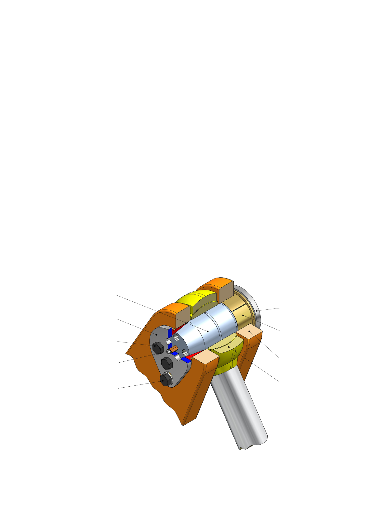
positioning plate
posisjoneringsplate
pin
bolt
screw
skrue
grease adapter & nipple
smøreforlenger & nippel
positioning details
posisjonerings-detaljer
plate
plate
conical sleeve
konhylse
support
innfestning
bearing
lager
1
bondura.no
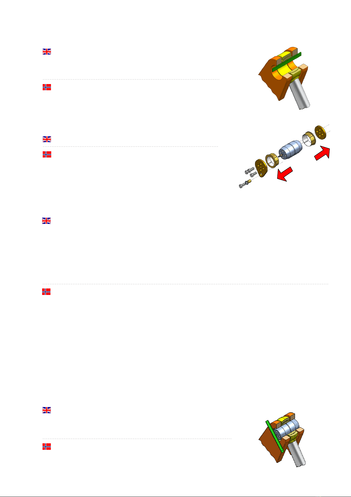
1.3/ Insert pin. The end surface of the pin must be ush with the support.
The pin needs to be centered. If the pin is not aligned correctly with the
support, the bondura® assembly may not funcon correctly.
Se inn bolt. Endeaten skal ligge jevnt med yersiden av innfestningen.
Bolten må være sentrert. Dersom endeaten ikke ligger jevnt med
yersiden på innfestningen kan dee hindre funksjonen l bondura®
sammensllingen.
1/ assembly
montering
1.1/ Preparing for installaon by centering and cleaning the pin bore.
Do not force the pin into a bore that is not properly aligned, this may
damage both pin and bearing.
Klargjøring for montering ved å sentrere og rengjøre bolt-hullet.
Dersom bolt presses inn i et hull som ikke er sentrert, kan både
bolt og lager skades.
1.2/ Prepare the bondura® assembly by removing the parts.
Klargjør bondura® sammensllingen ved å demontere delene.
2
Important!
The following fricon surfaces must always be clean, dry and free of any oil and grease substances when installing
the bondura® assembly:
• Contact surfaces between tapered end of bondura® pin and adjacent inner part of bondura® conical sleeve.
• Contact surfaces between outer part of bondura® conical sleeve and adjacent bore in support.
Warning!
If any oil or grease substance contaminates the fricon surfaces indicated above, it could lead to shear cung of
the screws and as a worst case scenario the complete pin assembly could disassemble and fall down.
Vikg!
Følgende friksjonsater må alld være rene, tørre og fri for olje- og festoer når bondura® sammensllingen blir
innstallert:
• Kontaklater mellom konisk ende på bondura® bolt og lstøtende indre del av bondura® konhylse.
• Kontaklater mellom utsiden av bondura® konhylse og lstøtende hull i innfestning.
Advarsel!
Dersom det er olje eller fe stoer på friksjonsatene angi ovenfor, kan det resultere i manglende festefriksjon,
og at strammeskruene kues av. Som en konsekvens av dee kan hele sammensllingen løsne og falle ned.
bondura.no
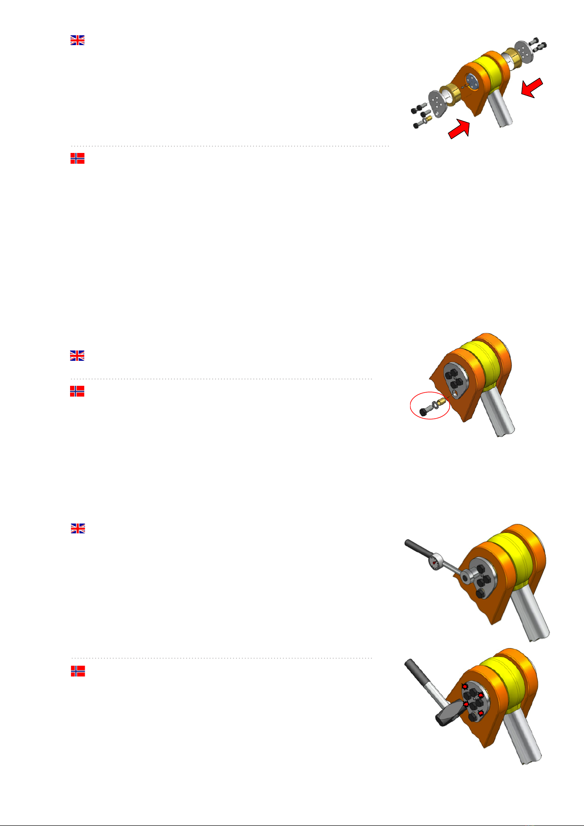
1.4/ Assemble the components.
bondura® technology guaranes correct installing torque assuming the
product is treated according to this assembly & inspecon manual, and
the torques are according to “technical specicaons/torque”. The
torques given in secon 2 are based on use of bondura® Assembly Paste.
By using other grease/lubricaon, or no lubricaon at all, bondura®
technology will not guarantee the installaon torque. By using correct
tread paste we ensure the correct torque.
Komponenter monteres.
bondura® technology garanterer korrekt oppspenningsmoment under
forutsetning av at produktet behandles i hht denne monterings- og inspeksjonsmanualen, og at ltreknings-
momentene er i hht “tekniske data/ltrekkingsmoment”. Tiltrekningsmomentene i punkt 2 forutseer bruk av
bondura® Assembly Paste. Ved bruk av annen gjengepasta, eller ingen bruk, så kan ikke bondura® garantere
oppspenningsmomentet. Bruk av korrekt gjengepasta sikrer korrekt ltrekningsmoment.
1.6/ Tighten all screws alternately at both ends. Ensure that the plate
always is parallel to the pin end. Tighten the screws to the specied
torque. See “technical specicaons/torque”.
Please note, it is important to tap with a hammer on the plates to
ensure the conical sleeves to expand correctly.
If it is expected a big temperature dierence (ΔT>50gr.C) on the
bondura® assembly between the me of torqueing and end of
operaon, it is recommended to contact bondura® technology to get
an assessment whether it is necessary to correct the torque.
Trekk l alle skruer vekselvis i begge ender, slik at platen alld ligger
parallelt med enden på bolten. Trekk skruer l oppgi moment.
Se “tekniske data/ltrekkingsmoment”.
Vær oppmerksom på at det er vikg å banke på platene for å sikre at
konhylsene ekspanderer korrekt.
Dersom det forventes stor temperatur forskjell (ΔT>50gr.C) på
bondura® sammensllingen, mellom ltrekningsdspunktet og
operasjonsdsløpet, så anbefales det å kontakte bondura® technology
for å få vurdert korrigerte ltrekningsmomenter.
3
1.5/ When posioning details are used, be aware to align the screw and
the threaded hole in the support.
Dersom posisjonerings-detaljer brukes, må skruen tree gjenget hull i
innfestningen.
bondura.no
4
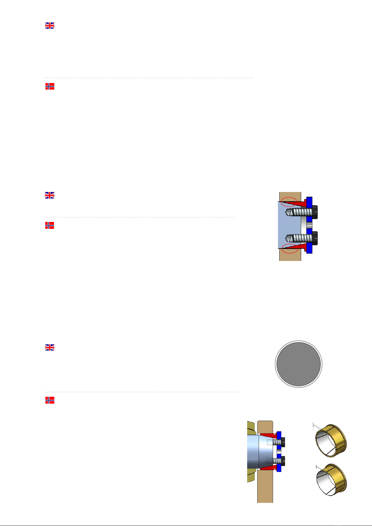
1.8/ The bondura® assembly locks to the support as the conical sleeves
expand and create a wedge-force between pin and support, and
thus prevent rotaon and sliding sideways.
bondura® sammensllingen låses mot rotasjon og utglidning ved at
konhylsene ekspanderer og skaper kilkra mellom bolt og innfestning.
1.9/ The conical sleeves expand and absorb up to 2mm (0,08”) gap/wear
between the pin and support. For larger clearances, oversize conical
sleeves must be used.
Oversize conical sleeves will be used in cases of more than 2mm
clearance due to wear, or as a replacement for a worn bushing.
Konhylsene ekspanderer og absorberer innl 2mm klaring/slark
mellom bolt og innfestning. Ved større klaring må overmål konhylse
benyes.
Overmål konhylser brukes hvor det er mer enn 2mm klaring på grunn
av slitasje eller som erstatning for utsli foringshylse.
Oversize conical sleeve
-----
Overmål konhylse
Standard conical sleeve
-----
Standard konhylse
1.7/ For installaon in perfectly circular bores, or new equipment:
Repeat ghtening and hammering unl specied torque value is achieved.
For installaon in bores with wear, tear and ovality, or used equipment:
Repeat ghtening and hammering unl specied torque value is achieved,
and then let the equipment run a few mes before repeang the ghtening
and hammering again unl specied torque value is achieved.
For installsjon i perfekt sirkulære hull, eller i ny utstyr:
Gjenta ltrekning og hamring l spesisert moment er oppnådd.
For installasjon i hull med slitasje og ovalitet, eller i brukt utstyr:
Gjenta ltrekning og hamring l spesisert moment er oppnådd, og la så
utstyret gå en stund før ltrekning og hamring gjentas innl spesisert
moment er nådd.

bondura.no
5
1.10/ The conical sleeves can repair up to 1mm (0,04”) ovality.
In case of more than 1mm ovality the oval hole should be
grinded rounder before installaon of the bondura® assembly.
Konhylsene kan reparere innl 1mm ovalitet.
Ved mer enn 1mm ovalitet bør det ovale hullet slipes rundere
før bondura® sammensllingen monteres.
1.11/ It is the ghtening regime of the screws, with subsequent conical
sleeve expansion, that allows the bondura® assembly to repair ovality
in the support.
Reghtening of the screws will be necessary during a period; unl
specied torque value is achieved.
Det er lstrammingen av skruer med påfølgende konhylse ekspansjon
som gjør at bondura® sammensllingen reparerer slark i innfestningen.
Eertrekking av skruer må uøres i en innkjøringsperiode innl
spesisert moment er oppnådd.
1.12/ Screws may be secured with wire locking.
Skruer kan sikres med trådlåsing.
1.13/ If the bondura® pin has a lubricaon channel/grease nipple; lubricate
the bearing to OEM’s recommendaon.
We recommend using bondura® Assembly Paste.
Single or double lubricaon groove from dia 114 ->
Dersom bondura® bolten har smørekanal/smørenippel; smøres lager
eer utstyrsprodusentens anbefaling.
Vi anbefaler å bruke bondura® Assembly Paste.
Enkelt eller dobbelt smørespor fra Ø114 ->
bondura.no
6
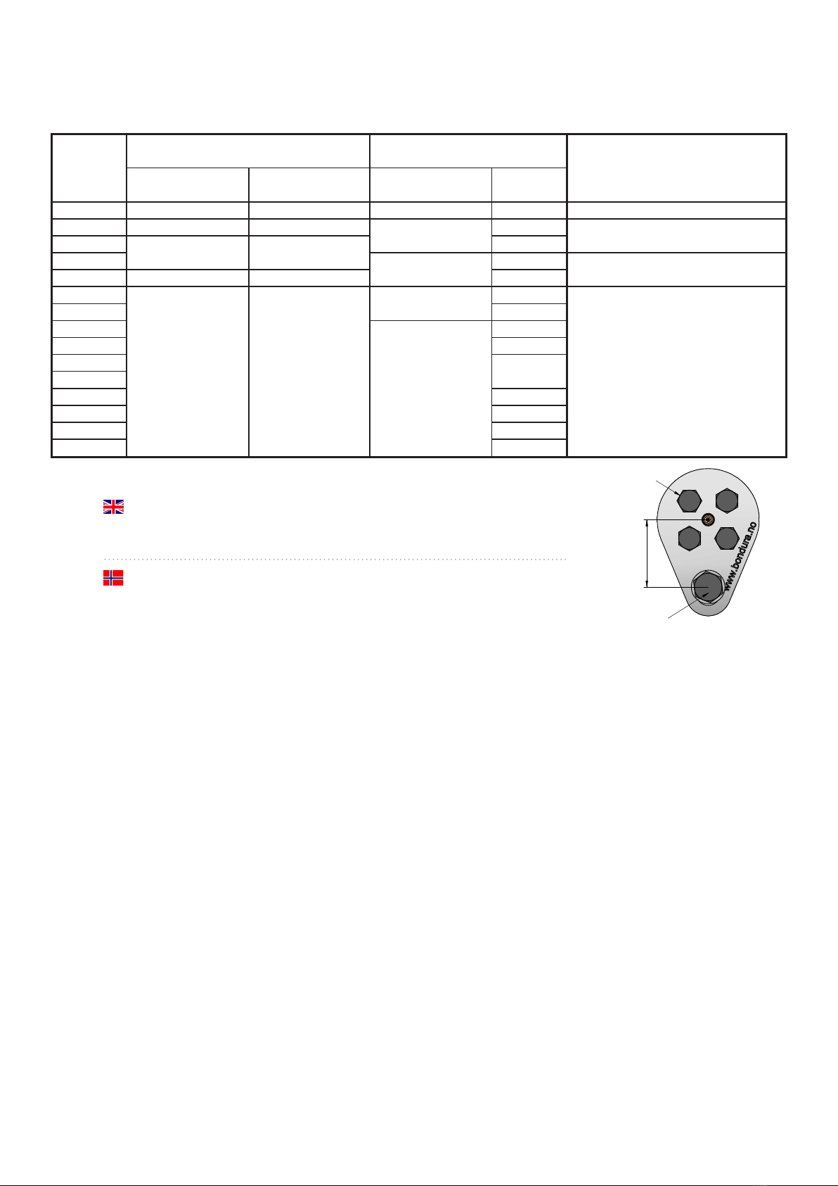
2/ technical specifications/torque
tekniske data/tiltrekkingsmoment
The specied torques are based on bondura® Assembly Paste to be used.
Use of other types of lubricaon, or no use of lubrucaon at all, will be the Customers own responsability.
ø50 -> 70 Means from ø50 (included) to ø70 (not included)
ø465 - ø500 Means from ø465 (included) to ø500 (included)
De spesiserte ltrekningsmomentene gjelder ved bruk av bondura® Assembly Paste (gjengepasta).
Bruk av annen smørning, eller ikke bruk av smørning, vil være brukerens eget ansvar.
ø50 -> 70 Betyr fra og med ø50 (inkludert) l ø70 (ikke inkludert)
ø465 - ø500 Betyr fra og med ø465 (inkludert) l ø500 (inkludert)
ø50 -> 70 35 55 7 - 12mm
ø70 -> 85 100 66
ø85 -> 100 76
ø100 ->114 85
ø114 ->140 300 100
ø140 -> 170 120
ø170 -> 200 133
ø200 -> 225 160
ø225 -> 260 185
ø260 -> 310
ø310 -> 330
ø330 -> 380 225
ø380 -> 420 266
ø420 -> 465 327
ø465 - ø500 354
Indicator X-value allowable range
Indikator X-verdi akseptert mellom
30 / (M20)
36 / (M24) 460
46 / (M30)
11 - 16mm
55 / (M36)
208
8 / (M10)
10 / (M12)
22 / (M14)
24 / (M16) 8 - 13mm
24 / (M16) 160
30 / (M20) 9 - 14mm
PIN size
Diameter
[mm]
Screw
Skrue
Positioning details
Posisjonerings-detaljer
Wrench size
Nøkkelvidde [mm]
Torque
Moment [Nm]
Wrench size
Nøkkelvidde [mm] C-C [mm]
bondura.no
3/ inspection
inspeksjon
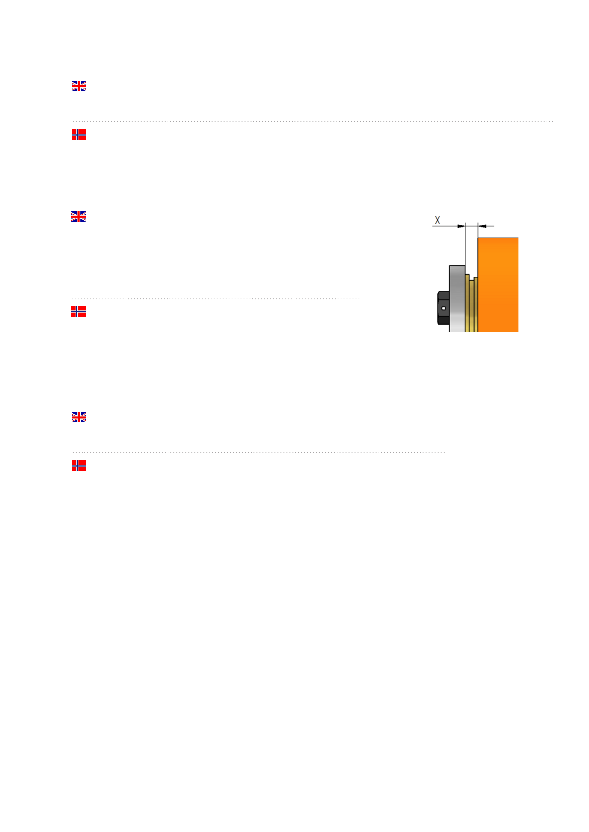
3.1/ Inspect Indicator X-value
Value less than shown in the “technical specicaons/torque”
can be an indicaon of the following:
a) The bondura® assembly has shied sideways.
See installaon secon 1.3.
b) There is a need for an oversize conical sleeve.
See secon 1.9.
Kontroller Indikator X-verdi
En lavere verdi enn vist i “tekniske data/ltrekkingsmoment”
kan være en indikasjon på følgende:
a) bondura® sammensllingen har forskjøvet seg sideveis.
Se montering punkt 1.3.
b) Det er behov for overmåls konhylse.
Se punkt 1.9.
3.2/ Inspect if the screws are loose, broken or missing.
a) Check that the torque is as specied in the “technical specicaons/torque”.
b) Install new screws if screws are missing.
Kontroller om skruer er løse, brukket eller mangler.
a) Kontroller at ltrekkingsmoment er som oppgi i “tekniske data/ltrekkingsmoment”.
b) Monter nye skruer dersom skruer mangler.
bondura® technology recommends the customer/user to implement a maintenance program to check the bondura®
assembly along with the specied service intervals for the relevant equipment. It is important to control and ensure
the expanding forces between conical sleeve and support, and reghten the screws if needed.
bondura® technology anbefaler kunde/bruker å implementere vedlikehold av bondura® sammensllingen i vedlike-
holdsprogrammet for aktuelt utstyr. Det er vikg å kontrollere og sikre ekspansjonskreer mellom konhylse og
innfestning, og eventuelt eertrekke skruene.
7

bondura.no
8
4/ disassembly
demontering
bondura® Mul Tool is a special tool for gentle and easy removal of
the conical sleeves and pin. It is suited for all types and dimensions
of bondura®. bondura® Mul Tool is available for both purchase and
rental. For further informaon, please visit our website www.bondura.no.
bondura® Mul Tool er et spesialverktøy for skånsom og enkel
demontering av konhylser og bolt. Det er lpasset alle bondura® typer
og dimensjoner. bondura® Mul Tool er lgjengelig både for salg og utleie.
For mer informasjon, vennligst se vår hjemmeside www.bondura.no.

bondura® technology AS
Vardheivegen 56b
4340 Bryne
Norway
support tel +47 51 77 20 20
post@bondura.no
bondura.no
Other Bondura Industrial Equipment manuals


