BONFIGLIOLI HDP Series User manual

INDUSTRY PROCESS
AND AUTOMATION SOLUTIONS
HDP
Installation, use and service manual


1
Revisions
Refer to page 38 for the catalogue revision index.
Visit www.bonfiglioli.com to search for catalogues with up-to-date revisions.
SUMMARY
Chapter
1 GENERAL INFORMATION ..............................................................3
1.1 PURPOSE OF THE MANUAL .......................................................... 3
1.2 EQUIPMENT IDENTIFICATION ........................................................4
1.3 GLOSSARY AND TERMINOLOGY ......................................................4
1.4 REQUESTING TECHNICAL ASSISTANCE ............................................... 5
1.5 MANUFACTURER’S LIABILITY.........................................................5
2 TECHNICAL INFORMATION ............................................................6
2.1 GEAR UNIT DESCRIPTION ...........................................................6
2.2 CONFORMITY TO STANDARDS .......................................................6
2.3 OPERATING LIMITS AND CONDITIONS ................................................. 6
3 SAFETY INFORMATION ................................................................7
3.1 SAFETY STANDARDS ...............................................................7
4 HANDLING AND TRANSPORT .......................................................... 9
4.1 PACKAGING .......................................................................9
4.2 HANDLING INSTRUCTIONS..........................................................10
4.2.1 HANDLING INSTRUCTIONS ........................................................10
4.2.2 MOVING PACKAGES .............................................................10
4.2.3 MOVING THE EQUIPMENT ........................................................10
4.3 STORAGE ........................................................................11
5 INSTALLATION ......................................................................12
5.1 INSTALLING ......................................................................12
5.1.1 GEAR UNIT .....................................................................12
5.1.2 GEAR UNITS EQUIPPED WITH SOLID SHAFT .........................................14
5.1.3 GEAR UNITS WITH HOLLOW OUTPUT SHAFT ........................................14
5.1.4 GEAR UNITS WITH SHRINK DISK ...................................................15
5.1.5 ANCHORING THE TORQUE ARM ...................................................16
5.1.6 GEAR UNIT EQUIPPED WITH MANIFOLD FLANGE .....................................16
5.1.7 GEAR UNIT EQUIPPED WITH FIXING FLANGE ........................................17
5.2 INSTALLING AN IEC-STANDARD FLANGED MOTOR .....................................17
5.3 INSTALLING CONNECTING ELEMENTS................................................18
5.4 GEAR UNIT TESTING AND START-UP .................................................18
5.5 USING THE EQUIPMENT ............................................................19
6 MAINTENANCE ......................................................................20
6.1 GENERAL INFORMATION ...........................................................20
6.2 ROUTINE MAINTENANCE ...........................................................21
6.3 LUBRICANTS......................................................................22
6.4 OIL CHANGE ......................................................................23
6.5 SERVICE PLUGS ..................................................................24
6.6 RECOMMENDED/PERMITTED OILS ...................................................25
6.7 CHECKING EFFICIENCY ............................................................25
6.8 CLEANING ........................................................................26
6.9 PAINT COATING ...................................................................26
7 INSTALLED COMPONENTS ...........................................................27
7.1 AUXILIARY THERMAL DEVICES ......................................................27
7.1.1 FORCED VENTILATION ...........................................................27
7.1.2 COOLING COIL ..................................................................27
7.1.3 OIL HEATER ....................................................................28
7.2 LUBRICATION SYSTEM .............................................................29
7.2.1 GENERAL INFORMATION .........................................................29
7.2.2 OIL SPLASH LUBRICATION ........................................................29
7.2.3 FORCED LUBRICATION ...........................................................29
7.2.4 FORCED LUBRICATION WITH PUMP ................................................29
7.2.5 FORCED LUBRICATION WITH MOTOR PUMP .........................................30
7.3 BACKSTOP DEVICE ................................................................30
7.4 DRYWELL ........................................................................31
7.5 SEALS AND GASKETS ..............................................................31
7.6 SENSORS ........................................................................31
7.7 OTHER ACCESSORIES .............................................................31
8 REPLACING PARTS..................................................................32
8.1 GENERAL INFORMATION ...........................................................32
8.2 DISASSEMBLING A GEAR UNIT EQUIPPED WITH HOLLOW OUTPUT SHAFT.................32
8.3 DISASSEMBLING A GEAR UNIT EQUIPPED WITH HOLLOW OUTPUT SHAFT
AND SHRINK DISC COUPLING .......................................................33
8.4 SCRAPPING THE GEAR UNIT ........................................................33
9 TROUBLESHOOTING.................................................................34
10 ANNEX 1 ...........................................................................35
10.1 CHECKING OIL LEVEL ..............................................................35
11 ANNEX 2 ...........................................................................36
11.1 METHOD OF LIFTING ...............................................................36
12 ANNEX 3 ...........................................................................37
12.1 CUSTOMER'S SHAFT series HDP .....................................................37
Description

2

1 GENERAL INFORMATION
1.1 PURPOSE OF THE MANUAL
This manual has been compiled by the Manufacturer to provide information on the safe transport,
handling, installation, maintenance, repair, disassembly and dismantling of the gear units.
All purchasing and design criteria is provided in the Sales Catalogue. Apart from adhering to
established engineering practices, the information given in this manual must be carefully read
and applied rigorously.
The information regarding the electric motor is supplied with the owner’
s manual relevant to the
specific electric motor.
Failure to adhere to the information provided herein may result in risk to personal health and safety,
and may incur economic damages.
This information, provided in the original language (Italian) of the Manufacturer, may also be made
available in other languages to meet legal and/or commercial requirements.
The documentation must be stored by a person with the correct authority and must always be made
available for consultation.
In case of loss or damage, replacement documentation must be requested directly from the
Manufacturer, quoting the code of this manual.
The manual reflects the state of the art at the time of commercialisation of the gear unit.
The Manufacturer reserves the right to modify, supplement and improve the manual, without the
present publication being for that reason considered inadequate.
Particularly significant sections of the manual and important specifications are highlighted by symbols
whose meanings are given below.
SYMBOLS:
DANGER - WARNING
This symbol indicates situations of serious danger which, if ignored, may result in
serious risks to the health and safety of personnel.
CAUTION - ATTENTION
This symbol indicates the need to adopt specific precautions to avoid risks to the
health and safety of personnel and possible economic damages.
IMPORTANT
This symbol indicates important technical information.
3

1.2 EQUIPMENT IDENTIFICATION
The gear unit bears the following nameplate. The nameplate bears all references and indispensable
safety instructions. The gear unit’s identifying code is explained in the Sales Catalogue.
If the gear unit is supplied complete with electric motor (gearmotor), all information regarding the motor
itself is supplied in the motor manual.
Nameplate data:
Gear unit type.
Product code.
Month / Year of manufacture.
Mounting position.
Gear ratio.
Readability of the nameplate
The nameplate and the information thereon must be readable at all times and consequently cleaned
from time to time.
Should the nameplate wear and/or become damaged so as to affect its readability or that of even one
of the items of information thereon, the User must request a new nameplate from the Manufacturer,
quoting the information given in this manual, and replace the old one.
1.3 GLOSSARY AND TERMINOLOGY
Some of the frequently occurring terms used in this manual are described below so as to
unequivocally define their meaning.
Routine maintenance:
the set of operations required for maintaining the functionality and efficiency of
the gear unit. These operations are usually scheduled by the Manufacturer, who defines the
qualifications required and tasks in question.
Non-routine maintenance: the set
of operations required for maintaining the functionality and
efficiency of the gear unit. These operations are not scheduled by the Manufacturer and must be done
by an expert maintenance technician.
Expert maintenance technician:
an authorised technician selected by means of having the
qualifications, skills and mechanical and electrical training to do repairs and non-
routine maintenance
work on the gear unit.
Overhaul:
an overhaul consists in the replacement of bearings and/or other mechanical components
which have worn to such an extent as to compromise the operation of the gear unit. The overhaul also
includes verification of the condition of all gear unit components (keys, seals, gaskets, vents, etc.). If
any such components are damaged they must be replaced and the reason for the damage identified.
4

1.4 REQUESTING TECHNICAL ASSISTANCE
For any technical service needs, contact the Manufacturer’
s sales network, quoting the information on
the unit’s nameplate, the approximate hours of service and the type of defect.
1.5 MANUFACTURER’S LIABILITY
The Manufacturer declines all liability for cases of:
use of the gear unit in violation of local laws on safety and accident prevention at work.
incorrect installation, disregard or incorrect application of the instructions provided in this
manual.
incorrect or defective power supply (gearmotors).
modifications or tampering.
work done on the unit by unqualified or unsuitable persons.
The safety of the gear unit also depends on scrupulous observance of the instructions given in this
manual, in particular:
always operate the unit within its operating limits.
diligently observe the routine maintenance schedule.
only authorise trained operators to inspect and service the unit.
use only original spare parts.
the configurations given in the gear unit catalogue are the only ones permitted.
do not attempt to use the unit contrary to the instructions supplied.
the instructions given in this manual do not substitute but summarise the provisions of
applicable safety legislation.
5
2 TECHNICAL INFORMATION
2.1 GEAR UNIT DESCRIPTION
The gear unit has been designed and constructed for integration, if required, driven by an electric
motor, into an assembly of interlocking parts or mechanisms as part of a specific application.
Depending on the requirements of the application, the gear unit can be supplied in a variety of
executions and configurations. It is capable of satisfying a range of specific requirements in the
mechanical, chemical, agricultural and food industries, etc.
BONFIGLIOLI RIDUTTORI supplies a range of accessories and optionals to make their products as
versatile as possible. For further technical information and descriptions, refer to the Sales Catalogue.
The User is responsible for using the products recommended for installation and maintenance of
BONFIGLIOLI gear units in an appropriate manner and in accordance with instructions.
2.2 CONFORMITY TO STANDARDS
All gear units are designed in compliance with the provisions of all applicable Essential Health and
Safety Requirements, “Machinery Directive”
98/37/EC and, if requested, can be supplied complete
with Manufacturer’s Declaration – Annex IIB as provided by said directive.
2.3 OPERATING LIMITS AND CONDITIONS
Ambient conditions
The gear unit must not be exposed do any harmful effects, e.g. caused by chemical products or
atmospheric pollution, nor exposed to ambient temperatures lower than -20°
C or higher than
+40°C.
Do not use the gear unit, if not explicitly intended for the purpose, in a potentially explosive
atmosphere or where the use of explosion-proof equipment is specified.
Lighting
If the unit is to be serviced in a poorly lit area, use additional lamps and ensure that the work is
done in compliance with applicable safety legislation.
Noise - Vibration
During operational testing at the Manufacturer’
s premises, the acoustic pressure measured
under full load at a distance of 1 m from the unit and 1.6 m above ground level without vibration
was less than 85 dB(A).
The vibrations produced by the gear unit do not constitute a health risk for personnel. Excessive
vibration may be the result of a fault and should be immediately reported and eliminated.
6

3 SAFETY INFORMATION
3.1 SAFETY STANDARDS
Carefully read the instructions given in this manual and those posted directly on the gear unit,
especially those regarding safety.
Persons charged with working on the gear unit at any time in its service life must be trained
specifically for the purpose with special abilities and experience in this area as well as being
equipped with the appropriate tools and individual safety equipment (as per Legislative Decree
626/94). Failure to meet these requirements constitutes a risk to personal health and safety.
Use the gear unit only for the applications envisaged by the Manufacturer. Improper use can
result in risks to personal health and safety and economic damages.
The applications defined by the Manufacturer are those industrial applications for which
the gear unit has been developed.
Keep the gear unit at its maximum efficiency by following the routine maintenance schedule.
Good maintenance enables the unit to operate at maximum performance over a long service life
in compliance with safety regulations.
When working on the unit in areas which are difficult to access or hazardous, ensure that
adequate safety precautions have been taken for the operator and others in compliance with the
provisions of law on health and safety at work.
All maintenance, inspection and repairs must only be done by an expert maintenance technician
fully familiar with the attendant hazards. It is, therefore, essential to implement operating
procedures which address potential hazards and their prevention for the entire machine. The
expert maintenance technician must always work with extreme caution in full compliance with
applicable safety standards.
During operation wear only the apparel and safety equipment indicated in the User instructions
provided by the Manufacturer or laid down by applicable laws on safety at work.
Replace worn components with original spare parts. Use the lubricants (oil and grease)
recommended by the Manufacturer.
Do not dump polluting materials into the environment. Dispose of all such materials as stipulated
by applicable legislation
Do not clean the gear unit using a high-pressure washer.
All work must be performed exclusively with the gear unit at a standstill.
The motor must be protected against inadvertent starts (e.g. with a lockout on the main power
switch or by removing the power fuses). For this purpose, also affix a notice to the motor
indicating that work is in progress on the gear unit.
Do not perform welding work on the gear unit.
The gear unit cannot be used as an earthing post for welding operations because this could
damage parts of the gear teeth and bearings.
The electric motor must be disconnected immediately if any alterations of the normal operation
of the gear unit are noted when it is running, such as an abnormal increase in operating
temperature or abnormal running noise.
The rotating parts of the gear unit must be protected by the manufacturer of the assembly in
which the gear unit is to be incorporated.
If the gear unit is to be installed in a plant or machine, the manufacturer of said plant or machine
is required to include the prescriptions, indications and descriptions contained in the present
handbook in its operating manual.
If the gear unit is installed in applications associated with a particularly high level of danger for
personal safety, e.g.:
suspended installations
motors supported exclusively by the gear unit
low speed shaft with shrink disc oriented downwards
or applications that can cause serious economic loss, or in the presence of high inertia loads, vibration,
etc. appropriate safety devices must be installed, such as harnesses, safety chains, restraining
systems, etc.
7

Various accessories (e.g. mounting flanges, ...) and/or electric motors coupled to the gear unit,
may significantly alter the centre of gravity, thereby impairing the stability of the unit.
Type of special danger
Depending on the operating conditions, the outer surfaces of the gear unit may reach very high
temperatures. Serious burns hazard!
When draining out spent oil at the time of an oil change, beware of the risk of serious burns
caused by hot oil!
In the presence of breather plugs with relief valve, wait for the oil in the gear unit to cool before
opening the plug and pay attention to the possible projection of jets of oil during transportation,
lifting, installation, adjustment, operation, cleaning, maintenance, repair, dismantling and
scrapping.
Wait for the gear unit to cool before inspecting it.
8
4 HANDLING AND TRANSPORT
4.1 PACKAGING
The standard packaging, when supplied and unless otherwise agreed, is not proofed against rainfall
and is intended for shipping by ground and not sea, and for environments which are under cover and
not humid.
The material can be stored in suitable conditions for a period of two years under cover at a temperature
between –15 °C and +50 °
C at a relative humidity not in excess of 80%. Storage in all other conditions
requires specific packaging.
In order to facilitate handling, heavy packages can be loaded on pallets.
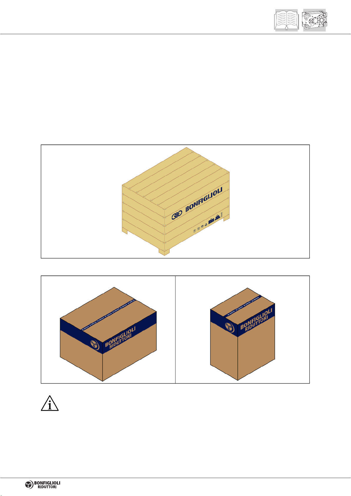
The most frequent types of packaging are shown in the figures below.
- Wooden crate for miscellaneous products shipped by sea.
- Carton pallet packaging for single products and kits.
Horizontal packaging Vertical packaging
On receipt of the gear unit, check that the delivery item corresponds to the purchase
order and that it is not damaged or faulty in any way. Refer any nonconformity to your
BONFIGLIOLI RIDUTTORI dealer.
Dispose of packaging materials as laid down by the provisions of law.
9
4.2 HANDLING INSTRUCTIONS
4.2.1 HANDLING INSTRUCTIONS
Handle packages as per the Manufacturer’
s instructions and those marked on the packages
themselves.
Since the weight and shape of packages may make manual handling unfeasible, special equipment
must be used to avoid damage and injury. Persons authorised for this purpose must be trained and
experienced in the work in question to safeguard his safety and that of all other persons involved.
The person authorised to handle the product must take all necessary precautions to
safeguard his safety and that of all other persons involved.
4.2.2 MOVING PACKAGES
Prepare a suitable, delimited area with a level floor or surface for unloading the packages.
Prepare the equipment required for handling the package. The lifting and handling equipment
used (e.g. crane or lift truck) must have adequate capacity for the weight and size of the load,
taking into account its attachment points and centre of gravity. If required, this information is
indicated on the package itself. Harness heavy packages with chains, belts and steel ropes
after checking that they are capable of sustaining the weight of the load, which is generally
specified.
When handling the load keep it level to avoid instability and/or tipping.
4.2.3 MOVING THE EQUIPMENT
All the following operations must be done with due care and caution and without
sudden movements.
Identify the attachment points for lifting the gear unit. Refer to Annex 4 of this manual for this
information.
Prepare the gear unit for lifting by attaching straps, hooks, shackles etc. to its attachment
points, or alternatively, use a pallet for moving the load. If using a crane, first lift the gear unit
vertically out of its packaging.
If using a lift truck or pallet truck, remove the packaging and fit the truck’
s forks at the indicated
positions.
First lift the load very slowly to check that it is stable.
Move the gear unit to the unloading area and lower it gently into position, taking care not to
cause sudden oscillations while moving it.
If the gear unit is coupled to an electric motor, do not use the eyebolts on the motor for
lifting the entire load, unless this is expressly indicated.
10

4.3 STORAGE
Some recommendations for storing the gear unit are indicated below.
1.
Do not store the unit in excessively humid conditions or where it is exposed to the weather (do
not store outdoors).
2. Do not place the gear unit directly on the ground.
3.
Place the gear unit on a stable base and make sure that it is not subjected to accidental
displacement.
4.
Store the packaged gear unit (if allowed) in accordance with the instructions on the packaging
itself.
When the gear unit is stored temporarily outdoors it must be protected to ensure that
humidity and extraneous objects cannot penetrate to the interior.
Special environmental conditions to be taken into account during shipment (e.g. by sea) and
storage (climate, presence of termites or similar) must be defined and established in the contract of
purchase.
If the gear unit is stored for more than 6 months, the following additional precautions must be taken:
5.
Cover all machined external surfaces with a rustproofing product such as Shell Ensis or
equivalent product with similar properties and application range.
6. Fill the unit with lubricating oil.
For gear units equipped with a drywell seal system or equipped with labyrinth type non-
contacting
seals, consult the BONFIGLIOLI technical-sales service.
11

5 INSTALLATION
5.1 INSTALLING
5.1.1 GEAR UNIT
The necessary clearances around the gear unit for installation and subsequent
maintenance work must be planned during the design phase.
If the gear unit is equipped with a fan adequate space must be provided for air
circulation.
Installation must be performed with care by skilled personnel. During the installation
procedure avoid all impact and forcing since this could cause damage to the internal
parts of the gear unit. We cannot be held liable for damage caused by incorrect
installation.
The person authorised to do the work must, if necessary, implement a safety plan to
safeguard all persons directly involved and rigorously apply all applicable legislation.
If a gearmotor is going to be installed, please consult the owner’
s manual of the electric motor
on beforehand.
Before installing the unit:
Thoroughly clean all packaging materials and protective product residue from the gear unit. Pay
particular attention to the coupling surfaces.
Check that the data on the nameplate corresponds to that which is specified on the order.
Ensure that the structure to which the gear unit is to be mounted is sufficiently robust and rigid to
support its weight and operating stresses.
Check that the machine on which the gear unit is to be installed is switched off and cannot be
accidentally switched on again.
Check that the surfaces on which the gear unit is to be installed are perfectly flat and level. Any
irregularities in the supporting surfaces may result in the transmission of tension to the outer
structure of the gear unit when the fixing bolts are tightened, with possible repercussions also on
the smooth running of the gears.
Check that all coupling surfaces are flat.
Fit suitable guards to protect against the external moving parts of the gear unit.
Check that there are no substances present in the place of installation that could cause
corrosion of the gear unit or its component parts. If there are any aggressive substances in the
environment, this situation must be communicated to the BONFIGLIOLI technical-
sales service,
which will provide suitable instructions.
If the gear unit is to be installed outdoors it must be protected from direct sunlight and inclement
weather by installing shields or guards, without impairing ventilation around the unit.
We recommend applying a protective paste to all couplings between the gear unit/motor and
other parts (Klü
berpaste 46 MR 401 or equivalent product with similar properties and application
range) to ensure optimal coupling and protection against fretting corrosion.
To ensure effective coupling, the driven shafts should be machined to the tolerances given in
tables in Annex 3 of this Manual.
12
In case of installation outdoors and when fitted with an electric motor, protect the latter from
direct sunlight and the weather by means of guards or a casing. Also make sure that the
assembly is properly ventilated.
Check on the gear unit nameplate that the configured mounting position corresponds to the
position specified in the order.
Now proceed with the installation as follows:
Place the gear unit in the vicinity of the installation area.
Mount the gear unit and secure it to the structure at the points provided. The gear unit should be
secured to the structure through all mounting points on the mount specified (feet or flange).
Tighten the anchor bolts only after having obtained an extensive contact zone between
the gear unit base and the foundation or between the connecting flanges.
After having tightened the fixing bolts check the alignment of the shafts again; said alignment
must also be checked and, if necessary, corrected after a few days of operation.
If the gear unit is supplied full of lubricant, identify the closed type plug utilised for transport
(usually red) and replace it with the breather plug supplied with the unit.
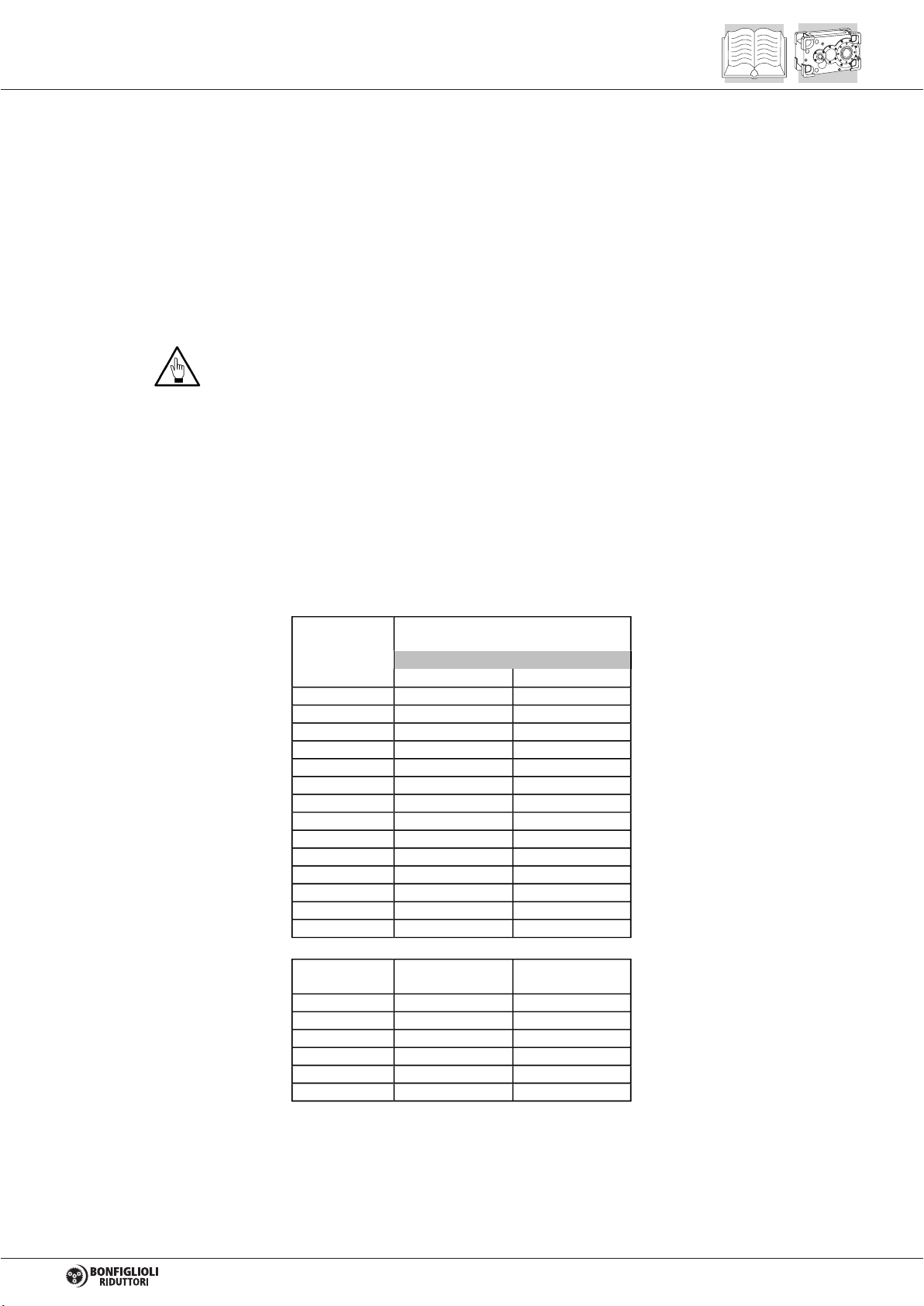
Tighten down the mounting bolts and check that the oil plugs are screwed down to the torque
given in table (A0).
(A0)
M4 3 3.8
M5 5.9 8.0
M6 10.3 13.0
M8 25.5 32
M10 50 64
M12 87.3 110
M14 138.3 180
M16 210.9 275
M18 306 390
M20 432 540
M22 592 720
M24 744 930
M27 1100 1400
M30 1500 1850
Bolt size
Tightening torque [Nm]
+5% /-10%
Bolt class
8.8 10.9
1/8" 28 5
1/4" 19 7
3/8" 19 7
1/2" 14 14
3/4" 14 14
1" 11 25
Cap/Vent
thread Pitch Tightening torque
[Nm]
13

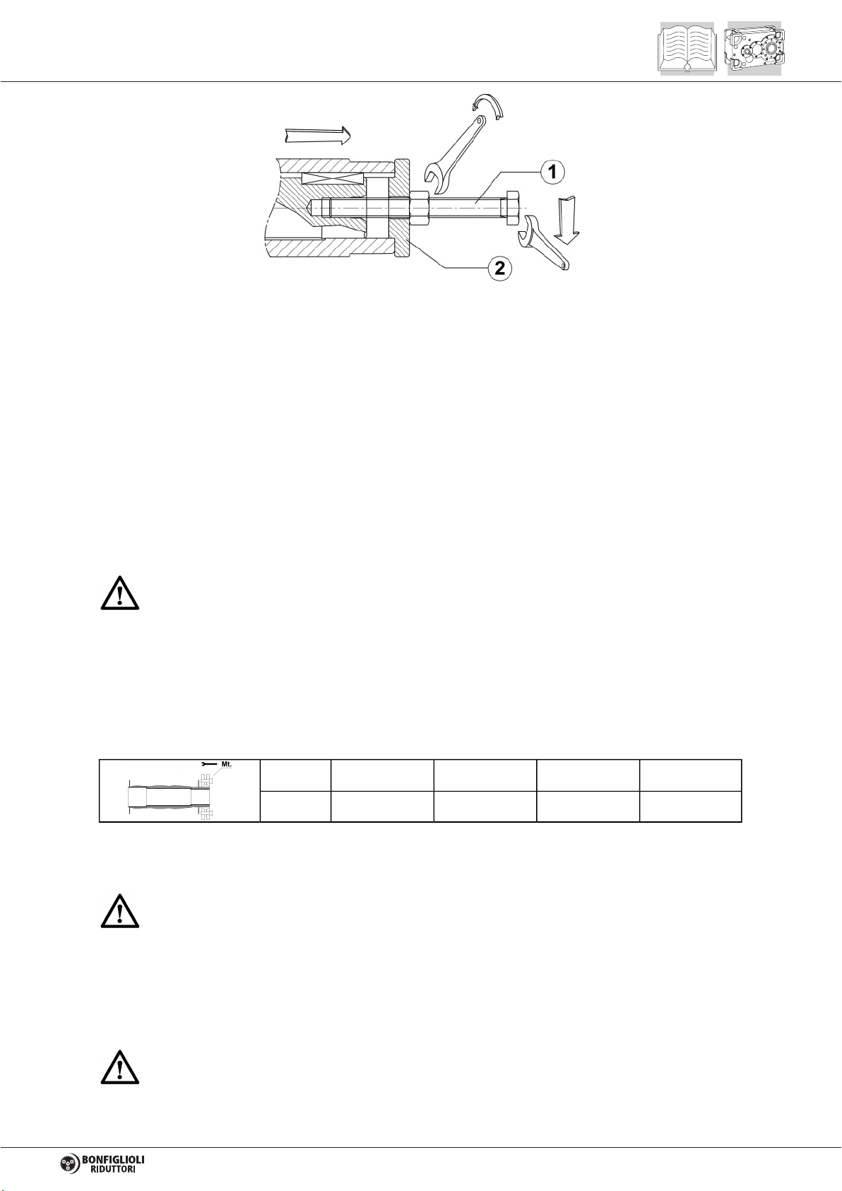
5.1.2 GEAR UNITS EQUIPPED WITH SOLID SHAFT
When installing external parts do not use hammers or other tools to avoid the risk of
damaging the gear unit shafts and supports. On the contrary, proceed as shown in the
following diagram, ideally preheating the part to be coupled. For further details refer to
heading 5.3
Bolt (1) and spacer (2) are to be supplied by customer.
To minimise the loads on the shaft bearings, when mounting transmission elements with asymmetrical
hubs, the preferred layout is shown in diagram (A) below:
(A)
5.1.3 GEAR UNITS WITH HOLLOW OUTPUT SHAFT
Before installing the gear unit by means of its hollow low speed shaft, perform the following operations:
1. Use petrol to remove any anti-corrosion coatings from the hollow shaft and the machine shaft.
In this case it is essential to avoid all contact between petrol and the shaft oil
seals.
2.
Check the hollow shaft and the machine shaft to ensure that the seats and edges are
undamaged.
To facilitate mounting hollow shaft gear units onto the machine’
s driven shaft, proceed as indicated in
the diagram below. Also refer to Annex 3 of this Manual for dimension information on customer’s shaft.
14
The bolt (1) and spacer (2) are to be supplied by customer.
Secure the hollow shaft to the machine shaft in an axial direction.
Install suitable devices to secure the hollow shaft to the machine shaft in an axial direction and prevent
accidental decoupling.
5.1.4 GEAR UNITS WITH SHRINK DISK
Gear units may be specified with a shrink disk for coupling onto the driven shaft. When installing a unit
of this type, proceed as follows:
1. Loosen the locking bolts gradually and in sequence and remove the entire shrink disk.
2. Clean and carefully degrease the coupling surface between the gear unit’
s output shaft and the
customer shaft.
Do not use molybdenum bisulphide or any other grease which would affect the friction
coefficient of the coupling surfaces and reduce the performance of the shrink disk.
3. Fit the gear unit onto the machine sliding its output shaft onto the driven shaft.
4. Fit the shrink disk to the gear unit shaft.
5.
Fully tighten down the shrink disk bolts gradually following a circular sequence using a torque
wrench.
This operation usually must be repeated several times to reach the tightening torque Mt
specified in the table below:
HDP 60 HDP 70 HDP 80 HDP 90
Mt [Nm] 35 35 69 127
Torque the shrink disc as prescribed to assure axial fixing of the transmission, in the absence of
external loads.
In the presence of external axial loads, vibration, safety problems, requirements for
enhanced reliability, or unfavourable mounting positions (e.g. V5 virtual mounting positions,
output shaft directed downwards), install suitable devices to secure the shaft in an axial
direction and prevent accidental decoupling.
The shrink disc coupling must not be disassembled nor lubricated before being reinstalled.
Disassemble and clean the shrink plate only when it is fouled.
When cleaning and/or during maintenance lubricate only the sliding surfaces of the
shrink disc using a solid lubricant with friction value of µ = 0.04, such as Klüber Molykombin
UMFT 1 (or an equivalent product having the same characteristics and durability of
performance)
15
Never run the gear unit when the shrink disc protective guard is not fitted.
5.1.5 ANCHORING THE TORQUE ARM
For shaft-mounting solutions the gear unit can be equipped with a torque arm on request.
This device, which is made of electrowelded steel and equipped with damper bushes, assures the
highest guarantees of functionality of the assembly because it is designed and sized specifically for
the job.
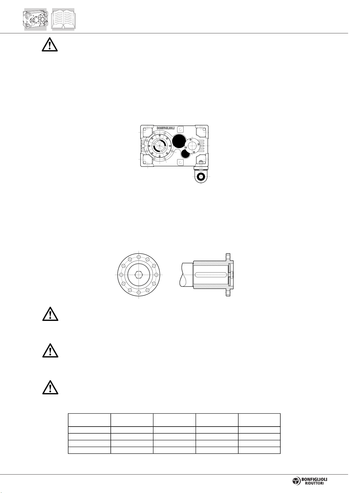
5.1.6 GEAR UNIT EQUIPPED WITH MANIFOLD FLANGE
Thoroughly clean and degrease the mating areas between the gear unit flange and
driven machine flange. The correct execution of this procedure is essential for safe torque
transmission. Do not use solvent with dirty rags to degrease the surfaces.
Do not use molybdenum disulphide or any other type of grease, as this would
significantly lower the friction coefficient in the contact area and therefore impair the
functionality of the coupling.
Tighten the bolts fully down, working in a crosswise sequence and applying the
maximum tightening torque shown in the chart by means of a torque wrench.
HDP 60 M18 cl. 10.9 cl. 10 435 Nm
HDP 70 M18 cl. 10.9 cl. 10 435 Nm
HDP 80 M20 cl. 10.9 cl. 10 615 Nm
HDP 90 M20 cl. 10.9 cl. 10 615 Nm
Screw Thread
UNI 5737 Nut
UNI 5588 Tightening
torque
16

5.1.7 GEAR UNIT EQUIPPED WITH FIXING FLANGE
The gear unit can be equipped with a fixing flange on request.
Thoroughly clean and degrease the mating areas between the gear unit flange and
driven machine flange. The correct execution of this procedure is an important factor in the
achievement of safe torque transmission. Do not use solvent with dirty rags to degrease the
surfaces.
Do not use molybdenum disulphide or any other type of grease, as this would
significantly lower the friction coefficient in the contact area and therefore impair the
functionality of the coupling.
Tighten the fixing bolts fully down, working in a crosswise sequence and applying the
maximum tightening torque shown in the chart by means of a torque wrench.
HDP 60 M16 cl. 10.9 cl. 10 314 Nm
HDP 70 M16 cl. 10.9 cl. 10 314 Nm
HDP 80 M16 cl. 10.9 cl. 10 314 Nm
HDP 90 M16 cl. 10.9 cl. 10 314 Nm
Screw Thread
UNI 5737 Screw
UNI 5588 Tightening
torque
5.2 INSTALLING AN IEC-STANDARD FLANGED MOTOR
Further to all the precautions indicated above, when installing a IEC-
flange mount electric motor the
following precautions must also be observed:
Do not force the coupling and do not use inappropriate tools during assembly. Take care not to
damage the flat and/or cylindrical coupling surfaces.
Do not force the shaft with large radial and/or thrust loads.
To facilitate assembly, use a lubricating synthetic oil paste such as Klü
berpaste 46 MR 401 or
equivalent product with similar properties and application range.
Tighten down all motor/gear unit mounting bolts to their prescribed torque. For the tightening
torques, refer to table (A0).
If the gear unit is installed in situations of particular hazardousness in relation to personal
safety install suitable safety devices, such as harnesses, safety chains, restraining systems, etc.
17

5.3 INSTALLING CONNECTING ELEMENTS
Use the utmost caution when installing the various components, to ensure that no damage is caused
to the gear unit and its parts, such as oil seals and mating surfaces, or internal parts such as gears
and bearings.
To perform the installation operations correctly ensure you have access to suitable lifting
equipment.
When installing external transmission parts do not use hammers or other unsuitable
tools, to avoid the risk of damaging the gear unit shafts and supports.
When installing connecting elements it is advisable to preheat them, taking care to:
Adopt protection against contact with hot parts: risk of burns!
Protect the oil seals from damage and accidental overheating to avoid impairing their
functionality (use a heat shield to protect against irradiated heat).
The connecting or transmission elements must not transmit external loads to the
shafts unless said loads have been calculated at the time of gear unit selection.
If the element to be coupled to the shaft is not fixed in an axial direction by the mechanical interference
of the coupling, utilise suitable retaining components able to prevent axial movement of the element in
question on the shaft.
5.4 GEAR UNIT TESTING AND START-UP
The gear unit has been factory tested by the Manufacturer.
Before starting the unit, check that:
The machine incorporating the gear unit complies with the provisions of the “
Machinery
Directive” 98/37/EC and any other applicable safety legislation.
The gear unit’
s mounting position in the installation corresponds to that prescribed and
indicated on the nameplate.
The electrical power supply and control systems are suitable and operational as stipulated in
standard EN 60204-1, and grounded as per standard EN 50014.
The motor power supply corresponds to that prescribed and is within ± 5% of the rated value.
The oil level is as prescribed and that there are no leaks from the caps or gaskets.
Before starting the gear unit read this handbook carefully. For correct operation of the gear unit it is
essential to comply strictly with the indications and prescriptions contained herein concerning correct
storage, use, and maintenance.
Check that the gear unit and any installed accessories that require oil, are filled to the correct level
after having connected all parts and accessories that were previously removed for shipment.
In the presence of optional accessories it is also necessary to check that all the operations required for
their correct functioning have been carried out as described in the relative chapters. When the gear
unit is started for the first time it must run for at least 8 hours in no load conditions. If no irregular
operation is noted during this period, the load can be gradually increased to the rated operating
conditions over a reasonable period of time during which the gear unit must be monitored closely.
18
Other manuals for HDP Series
2
This manual suits for next models
4
Table of contents
Other BONFIGLIOLI Industrial Equipment manuals


