BONFIGLIOLI HDP Series User manual


1
SOMMARIO
Descrizione Description Beschreibung
1 INFORMAZIONI GENERALI GENERAL INFORMATION ALLGEMEINE INFORMATIONEN 2
1.1 SIMBOLOGIA E UNITÀ DI MISURA SYMBOLS AND UNITS OF MEASUREMENT SYMBOLE UND MASSEINHEITEN 2
1.2 CARATTERISTICHE COSTRUTTIVE PRODUCT FEATURES BAULICHE EIGENSCHAFTEN 3
1.3 INSTALLAZIONE INSTALLATION INSTALLATION 4
1.4 MANUTENZIONE MAINTENANCE WARTUNG 5
1.5 STOCCAGGIO STORAGE LAGERUNG 6
1.6 CONDIZIONI DI FORNITURA CONDITIONS OF SUPPLY LIEFERBEDINGUNGEN 6
1.7 VERNICIATURA PAINT COATING LACKIERUNG 6
1.8 FATTORE DI SERVIZIO SERVICE FACTOR BETRIEBSFAKTOR 7
1.9 LUBRIFICAZIONE LUBRICATION SCHMIERUNG 11
2 SELEZIONE DEL RIDUTTORE SELECTING THE GEAR UNIT WAHL DES GETRIEBES 13
2.1 DIMENSIONAMENTO ENGINEERING SELECTION BEMESSUNG 13
2.2 VERIFICHE VERIFICATIONS KONTROLLEN 14
2.3 CASO APPLICATIVO SAMPLE APPLICATION ANWENDUNGSFALL 21
3 CONFIGURAZIONI PRODOTTO PRODUCT CONFIGURATIONS PRODUKTKONFIGURATIONEN 22
3.1 VARIANTI BASE BASE VARIANTS BASISVARIANTEN 22
3.2 VARIANTI OPZIONALI OPTIONAL VARIANTS OPTIONALE VARIANTEN 23
3.3 POSIZIONI DI MONTAGGIO MOUNTING POSITION EINBAULAGEN 24
3.4 CONFIGURAZIONE LATO INGRESSO
E USCITA INPUT AND OUTPUT CONFIGURATION KONFIGURATION ANTRIEBS UND
ABTRIEBSSEITE 24
3.5 PREDISPOSIZIONI MOTORE MOTOR AVAILABILITY MOTORAUSLEGUNGEN 27
3.6 VARIANTI OPZIONALI OPTIONAL VARIANTS OPTIONALE VARIANTEN 28
4 COPPIA MASSIMA TRASMISSIBILE MAXIMUM TRANSMISSIBLE TORQUE ÜBERSETZBARES MAXIMALES
DREHMOMENT 45
4.1 POTENZA TERMICA E DATI TECNICI THERMAL CAPACITY AND RATING
CHARTS
WARMELEISTUNG UND
AUSWAHLTABELLEN 46
4.2 CARICHI RADIALI ALBERO LENTO PERMITTED OVERHUNG LOADS ON
OUTPUT SHAFT
RADIALKRÄFTE ABTRIEBSWELLE 118
4.3 CARICHI ASSIALI ALBERO LENTO PERMITTED THRUST LOAD ON OUTPUT
SHAFT
AXIALKRÄFTE ABTRIEBSWELLE 131
4.4 MOMENTO D’INERZIA MASS MOMENT OF INERTIA TRÄGHEITSMOMENT 144
4.5 RAPPORTI ESATTI EXACT RATIOS EXAKTE ÜBERSETZUNG 145
5 DIMENSIONI E PESI DIMENSIONS AND WEIGHT ABMESSUNGEN UND GEWICHTE 146
5.1 PREDISPOSIZIONE ATTACCO MOTORE
CON CAMPANA E GIUNTO ELASTICO MOTOR MOUNTING WITH BELL HOUSING
AND FLEXIBLE COUPLING
AUSLEGUNG FÜR MOTORANSCHLUSS MIT
GLOCKE UND ELASTISCHER KUPPLUNG 168
5.2 FLANGIA DI FISSAGGIO MOUNTING FLANGE BEFESTIGUNGSFLANSCH 171
5.3 FLANGIA A MANICOTTO MANIFOLD FLANGE AUFSTECKFLANSCH 171
5.4 PERNO MACCHINA CUSTOMER’S SHAFT MASCHINENZAPFEN 172
Paragrafo
Chapter
Abschnitt
Revisions
Refer to page 174 for the catalogue revision in-
dex. Visit www.bonfiglioli.com to search for cata-
logues with up-to-date revisions.
Änderungen
Das Revisionsverzeichnis des Katalogs wird auf
Seite 174 wiedergegeben. Auf unserer Website
www.bonfiglioli.com werden die Kataloge in ihrer
letzten, überarbeiteten Version angeboten.
Revisioni
L’indice di revisione del catalogo è riportato a
pag. 174. Al sito www.bonfiglioli.com sono dispo-
nibili i cataloghi con le revisioni aggiornate.
SUMMARY ZUSAMMENFASSUNG

2
Descrizione Description Beschreibung
An 1,2 [kN] Carico assiale nominale Permissible axial force Nominale Axialkraft
fS- Fattore di servizio Service factor Betriebsfaktor
i- Rapporto di trasmissione Gear ratio Übersetzung
I- Rapporto di intermittenza Cyclic duration factor Relative Einschaltdauer
J[Kgm2] Momento di inerzia Mass moment of inertia Trägheitsmoment
M1,2 [Nm] Coppia Torque Drehmoment
Mc 1,2 [Nm] Coppia di calcolo Calculated torque Rechnerisches Drehmoment
Mn 1,2 [Nm] Coppia nominale Rated torque Nennmoment
Mr 1,2 [Nm] Coppia richiesta Torque demand Benötigtes Drehmoment
n1,2 [min-1] Velocità Speed Drehzahl
P1,2 [kW] Potenza Power Leistung
Pn 1,2 [kW] Potenza nominale Rated power Nennleistung
Pr 1,2 [kW] Potenza richiesta Power demand Benötigte Leistung
Rc 1,2 [kN] Carico radiale di calcolo Calculated radial force Rechnerische Radialkraft
Rn 1,2 [kN] Carico radiale nominale Permissible overhung load Nominale Radialkraft
h- Rendimento Efficiency Wirkungsgrad
1 - INFORMAZIONI GENERALI
1.1 - SIMBOLOGIA E UNITÀ
DI MISURA
1 - GENERAL INFORMATION
1.1 - SYMBOLS AND UNITS
OF MEASUREMENT
1 - ALLGEMEINE INFORMATIONEN
1.1 - SYMBOLE UND
MASSEINHEITEN
1valore riferito all’albero veloce
2valore riferito all’albero lento
1value applies to input shaft
2value applies to output shaft
1Auf die Antriebswelle bezogener
Wert
2Auf die Abtriebswelle bezogener
Wert

3
1.2 - CARATTERISTICHE
COSTRUTTIVE
I riduttori della serie HDP sfruttano tec-
niche progettuali all’avanguardia ed of-
frono pertanto:
•Elevate coppie specifiche
•Rendimenti superiori
•Vibrazione e rumorosità ridotte
•Robustezza e affidabilità assolute
•Calcoli di vita secondo le Norme ISO
e AGMA applicabili
•Ampia personalizzazione tramite la
vasta gamma di opzioni offerte a ca-
talogo
Le principali caratteristiche costruttive della
serie di riduttori ad assi paralleli HDP sono:
•grandezze da HDP 60 a HDP 90 a 2
e 3 stadi di riduzione
•grandezze da HDP 100 a HDP 160 a
2, 3 e 4 stadi di riduzione.
•Valori di coppia nominale con distri-
buzione favorevole su tutto l’arco dei
rapporti.
•Rapporti di trasmissione con progres-
sione costante del 12%.
•HDP 60 ... HDP 120: Cassa mono-
blocco in ghisa sferoidale, rigida, resi-
stente e precisa, verniciata interna-
mente ed esternamente. Design mo-
derno e privo di recessi a garanzia di
una pulizia facilitata. Fissaggio univer-
sale grazie alle numerose superfici la-
vorate e forate. Forme e spessori otti-
mizzati mediante l’analisi FEM garan-
tiscono elevata rigidezza strutturale e
ridotte emissioni acustiche.
•HDP 130 ... HDP 160: Cassa in ghisa
sferoidale realizzata in due semigusci,
con piano di separazione complanare
agli assi. L’architettura consente di rea-
lizzare interventi di manutenzione in
maniera efficace ed economica. Forme
e spessori ottimizzati mediante l’analisi
FEM garantiscono elevata rigidezza
strutturale e ridotte emissioni acustiche.
•Ingranaggi elicoidali in acciaio legato,
cementati e temprati, con correzione
del profilo per:
- ridurre la rumorosità e favorire la re-
golarità della trasmissione degli ingra-
naggi veloci
- massimizzare la coppia trasmissibile
delle riduzioni finali
•Alberi veloci generalmente cementati
e rettificati e alberi lenti in acciaio da
bonifica di elevata rigidezza.
1.2 - PRODUCT FEATURES
Gear units of the HDP series make opti-
mum use of advanced design features,
to offer:
•Top torque density
•Superior performance
•Silent and vibration-free operation
•Total ruggedness and reliability
•Lifetime calculation in accordance
with the applicable ISO and AGMA
standards
•Extensive customisation through a
wide range of options offered in the
catalogue
The main construction features of the
HDP parallel shaft gear unit range are:
•sizes from HDP 60 to HDP 90 with
double and triple reduction.
•sizes from HDP 100 to HDP 160 with
double, triple and quadruple reduction.
•Favourable distribution of rated torque
values across the entire ratio range.
•Gear ratios in a 12% progression be-
tween consecutive values.
•HDP 60 ... HDP 120: Monobloc housing
in rigid, spheroidal cast iron, paint
coated both internally and externally.
A modern design without recesses
for facilitated cleaning. Universal
mounting thanks to the many ma-
chined surfaces. Profiles and dimen-
sions optimised by FEM analysis for
superior structural rigidity and low
acoustic emissions.
•HDP 130 ... HDP 160: housing in
spheroidal cast iron, horizontally split.
This design makes maintenance quick
and economical. Profiles and dimen-
sions optimised by FEM analysis for
superior structural rigidity and low
acoustic emissions.
•Casehardened and hardened alloy
steel helical gears ground finished
and with profile corrected for:
- more silent operation and smoother
transmission of high speed input gears
- maximum transmissible torque of the
lower speed output gear reductions
•Input shafts generally casehardened and
ground finished on outer diametre.
Output shafts from hardened and tem-
pered alloy steel.
•Input shaft configurations:
- HDP 60 ... HDP 160: solid, single or
double-sided shaft with dimensions to
UNI/ISO 775-88 (extended length)
1.2 - BAULICHE EIGENSCHAFTEN
Die Getriebe der Serie HDP nutzen mo-
dernste Entwicklungstechniken und bie-
ten daher:
•Hohe spezifische Drehmomente
•Hohe Wirkungsgrade
•Reduzierte Vibration und Geräusch-
entwicklung
•Robuste Bauweise und absolute Zu-
verlässigkeit
•Lebensdauerberechnung gemäß den
einschlägigen ISO- und AGMA-Normen
•Kundenspezifische Anpassung dank
einer großen Auswahl an Optionen im
Katalog
Die wichtigsten baulichen Merkmale der
Parallelwellengetriebe HDP sind:
•Baugrößen HDP 60 bis HDP 90 mit 2
und 3 Untersetzungsstufen.
•Baugrößen HDP 100 bis HDP 160 mit
2, 3 und 4 Untersetzungsstufen.
•Nennmomentwerte mit günstiger Ver-
teilung auf den gesamten Überset-
zungsbereich.
•Übersetzungsverhältnisse mit konstan-
tem Stufensprung von 12%.
•HDP 60 ... HDP 120: Starres, wider-
standsfähiges und präzises Monoblockge-
häuse aus Sphäroguss, innen und außen
lackiert. Modernes Design ohne Einbuch-
tungen für eine einfache Reinigung.
Universalbefestigung dank den zahlrei-
chen bearbeiteten Oberflächen. Mittels
FEM-Analysen optimierte Formen und
Abmessungen garantieren hohe Struktur-
steifheit und reduzierte Schallemissionen.
•HDP 130 ... HDP 160: Aus zwei Halb-
schalen gefertigtes Sphäroguss-Gehäu-
se mit direkt an den Achsen anliegender
Trennfläche. Dank entsprechender Kon-
struktion können Wartungsarbeiten wirk-
sam und ökonomisch ausgeführt werden.
Mittels FEM-Analysen optimierte Formen
und Abmessungen garantieren hohe
Struktursteifheit und reduzierte Schall-
emissionen.
•Einsatzgehärtete Schrägzahnräder aus
legiertem Stahl mit geschliffener Ver-
zahnung, optimiert um:
- die Geräuschentwicklung zu verringern
und eine gleichmäßigere Übertragung
zwischen den Zahnrädern zu erzielen
- das übertragbare Drehmoment der
Enduntersetzungen auf ein Höchstmaß
zu steigern
•Die Antriebswellen sind generell ein-
satzgehärtet und geschliffen. Ab-

4
•Configurazioni alberi veloci:
- HDP 60 ... HDP 160: albero cilindri-
co, a semplice o doppia sporgenza,
con estremità secondo UNI/ISO
775-88 (serie lunga)
- HDP 60 ... HDP 90: predisposizione
per attacco diretto al motore oppure
tramite giunto elastico di collegamento.
- HDP 100 ... HDP 160: predisposizio-
ne motore mediante campana di col-
legamento e giunto elastico.
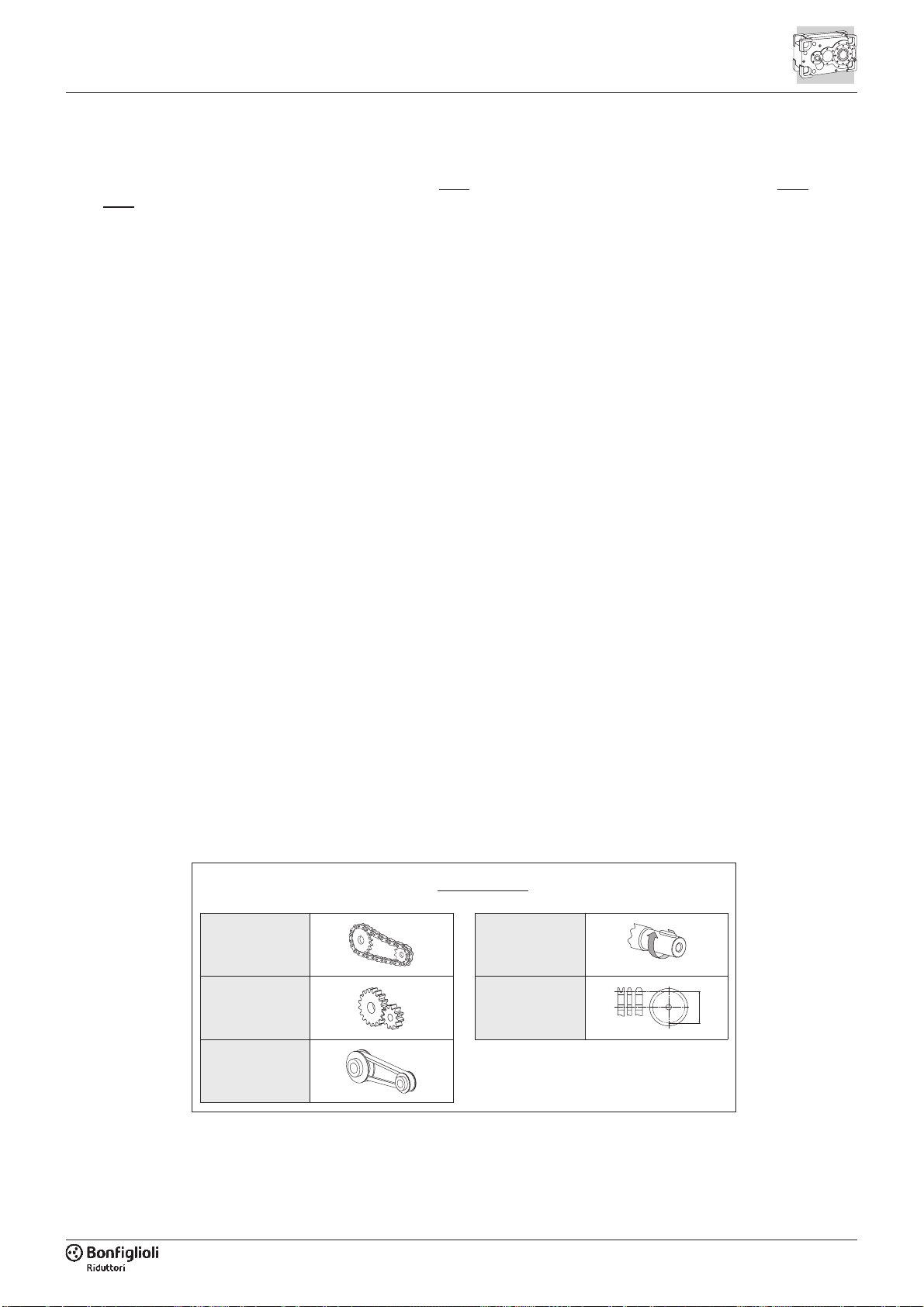
•Configurazioni alberi lenti:
- albero cilindrico integrale, a singola o
doppia sporgenza, con estremità se-
condo UNI/ISO 775-88 (serie lunga)
- albero cavo con sede per linguetta
- albero cavo con calettatore
•Cuscinetti delle primarie marche del
tipo a rulli conici oppure orientabili a
rulli largamente dimensionati e idonei
a sopportare elevati carichi esterni.
•Numerose possibilità di personalizza-
zione del riduttore tramite le opzioni a
richiesta, fra le quali:
- dispositivi termici di raffreddamento /
riscaldamento ausiliari
- sistemi di lubrificazione forzata
- dispositivo antiretro
- flangie di fissaggio, o a manicotto
- cuscinetti per sopportazione radiale
maggiorata (solo per HDP 60 ... HDP 90)
- tenute e guarnizioni di diverso tipo e
materiale
- sensori
- dispositivo dry-well per installazioni
con albero verticale
- organi di fissaggio
- HDP 60 ... HDP 90: direct motor
mounting or lantern housing and flexi-
ble coupling provision.
- HDP 100 ... HDP 160: motor mount-
ing with bell and housing and flexible
coupling.
•Output shaft configurations:
- solid, single or double-sided shaft
with dimensions to UNI/ISO 775-88
(extended length)
- hollow shaft with keyway
- hollow shaft with shrink disc
•Heavy duty taper roller bearings or ex-
tra large self-aligning roller bearings
from the most reputed brands for un-
paralleled overhung load capacity.
•A wide range of customisation options
are available upon request, including:
- auxiliary cooling/heating devices
- forced lubrication systems
- backstop device
- mounting or manifold flanges
- bearings for increased overhung load
capacity (only for HDP 60 ... HDP 90)
- seals and gaskets in various types
and materials
- sensors
- dry-well device for vertical shaft in-
stallations
- fixing elements
triebswellen aus Vergütungsstahl mit
hoher Festigkeit.
•Konfigurationen der Antriebswellen:
- HDP 60 ... HDP 160: Zylindrische
Passfederwelle mit ein- oder zweifa-
chem Wellenzapfen. Wellenende ge-
mäß UNI/ISO 775-88 (lange Serie)
- HDP 60 ... HDP 90: Vorbereitung für
Direktmontage des Motors oder über
elastische Kupplung.
- HDP 100 ... HDP 160: Motoradapti-
on mittels Verbindungsglocke und
elastischer Kupplung.
•Konfigurationen der Abtriebswellen:
- Zylindrische Passfederwelle mit ein-
oder zweifachem Wellenzapfen. Wel-
lenende gemäß UNI/ISO 775-88 (lan-
ge Serie)
- Hohlwelle mit Passfedernut
- Hohlwelle mit Schrumpfscheibenver-
bindung.
•Großzügig bemessene Kegelrollenla-
ger oder Pendelrollenlager führender
Hersteller, geeignet, um hohen exter-
nen Krafteinwirkung standzuhalten
•Zahlreiche Möglichkeiten der kunden-
spezifische Anpassung des Getriebes
mit den auf Anfrage erhältlichen Op-
tionen, unter anderem:
- Thermische Vorrichtung zur Küh-
lung/Wärmung der Getriebe
- Systeme zur Zwangsschmierung
- Rücklaufsperre
- Montageflansche oder Aufsteckflansche
- Lager für erhöhte radiale Widerstands-
kraft (nur für HDP 60 ... HDP 90)
- Verschiedene Arten von Dichtungen
aus unterschiedlichen Materialien
- Sensoren
- Vorrichtung Drywell für Installationen
mit senkrechter Welle
- Befestigungselemente
1.3 - INSTALLAZIONE
È molto importante, per l’installazione del
riduttore, attenersi alle seguenti norme:
•Assicurarsi che il fissaggio del ridutto-
re sia stabile onde evitare qualsiasi vi-
brazione. Installare (se si prevedono
urti, sovraccarichi prolungati o possi-
bili bloccaggi) giunti idraulici, frizioni,
limitatori di coppia, ecc.
•Durante la verniciatura si dovranno pro-
teggere i piani lavorati e il bordo ester-
no degli anelli di tenuta per evitare che
la vernice ne essichi la gomma, pregiu-
dicando la tenuta del paraolio stesso.
•Si consiglia di lavorare gli organi che
vanno calettati sugli alberi di uscita
1.3 - INSTALLATION
The following installation instructions
must be observed:
•Make sure that the gearbox is cor-
rectly secured to avoid vibrations.
If shocks or overloads are expected,
install hydraulic couplings, clutches,
torque limiters, etc.
•Before being painted, the machined
surfaces and the outer face of the
oilseals must be protected to prevent
paint drying out the rubber and jeop-
ardising the oil-seal function.
•Components to be keyed on to the
gearbox output shafts should be ma-
chined to ISO H7 tolerances to pre-
1.3 - INSTALLATION
Beim Einbau des Getriebes sind folgen-
de Vorschriften strikt zu befolgen:
•Um Vibration zu vermeiden sicherstel-
len, dass die Getriebe korrekt befes-
tigt sind. Wenn Stöße, anhaltende
Überlasten oder mögliche Blockierun-
gen erwartet werden, Strömungs-
kupplungen, Kupplungen, Drehmo-
mentbegrenzer usw. installieren.
•Während der Lackierung müssen die
bearbeiteten Flächen und die Außen-
kante der Dichtringe geschützt wer-
den, damit der Lack nicht das Gummi
austrocknet, und somit die Funktion
des Dichtrings.

5
del riduttore con tolleranza ISO H7
per evitare accoppiamenti troppo
bloccati che, in fase di montaggio po-
trebbero danneggiare irreparabilmen-
te il riduttore stesso. Inoltre, per il
montaggio e lo smontaggio di tali or-
gani si consiglia l’uso di adeguati ti-
ranti ed estrattori utilizzando il foro fi-
lettato posto in testa alle estremità
degli alberi.
•Le superfici di contatto dovranno es-
sere pulite e trattate con adeguati
protettivi prima del montaggio, onde
evitare l’ossidazione e il conseguente
bloccaggio delle parti.
•Prima della messa in servizo del ri-
duttore accertarsi che la macchina
che lo incorpora sia in regola con le
disposizioni della Direttiva Macchine
2006/42/CE e successivi aggiorna-
menti.
•Prima della messa in funzione della
macchina, accertarsi che la posizione
del livello del lubrificante sia conforme
alla posizione di montaggio del ridut-
tore e che la viscosità sia adeguata al
tipo di applicazione.
•Nel caso di istallazione all’aperto pre-
vedere adeguate protezioni e/o carte-
rature allo scopo di evitare l’esposi-
zione diretta agli agenti atmosferici e
alla radiazione solare.
•Die Komponenten, die auf die Ab-
triebswellen des Getriebes aufgezo-
gen werden, sollten die Toleranz ISO
H7 aufweisen, damit zu fest sitzende
Verbindungen vermieden werden,
durch die das Getriebe bei der Monta-
ge irreparabel beschädigt werden
könnte. Für den Ein- und Ausbau die-
ser Elemente wird außerdem die Ver-
wendung geeigneter Zugstreben oder
Abzieher empfohlen, die an der Ge-
windebohrung an der Stirnseite am
Wellenende angesetzt werden.
•Die Kontaktflächen müssen vor der
Montage gesäubert und mit geeigneten
Schutzprodukten behandelt werden,
um eine Oxidation und folglich die Blo-
ckierung der Teile, zu verhindern.
•Vor Inbetriebnahme des Getriebes si-
cherstellen, dass die Maschine, in die
es eingebaut wird, die Vorschriften
der Maschinenrichtlinie 2006/42/CE in
gültiger Fassung erfüllt.
•Vor Inbetriebnahme der Maschine
muss sichergestellt werden, dass der
Schmiermittelstand der Einbaulage des
Getriebes entspricht und die Viskosität
für die Art der Applikation geeignet ist.
•Bei Installation im Freien müssen ge-
eignete Schutzvorrichtungen und/oder
Schutzgehäuse vorgesehen werden,
um die Getriebe vor direkten Witte-
rungseinflüssen und Sonneneinstrah-
lung zu schützen.
vent mating surfaces jamming and
causing irreparable damage to the
gearbox during installation. Suitable
pullers and extractors should also be
used to fit and remove such compo-
nents. These should be properly se-
cured to the threaded hole at the end
of the shafts.
•Mating surfaces must be cleaned and
treated with suitable protective prod-
ucts before mounting to avoid oxida-
tion and, as a result, seizure of parts.
•Prior to putting the gear unit into oper-
ation make sure that the equipment
that incorporates the same complies
with the current revision of the Ma-
chines Directive 2006/42/CE.
•Before starting up the machine, make
sure that oil level conforms to the
mounting position specified for the
gear unit and viscosity is suitable for
the specific application.
•For outdoor installation provide ade-
quate guards in order to protect the
drive from rainfalls as well as direct
sun radiation.
1.4 - MANUTENZIONE
Si consiglia di effettuare una prima sosti-
tuzione del lubrificante dopo circa 300
ore di funzionamento, provvedendo ad
un accurato lavaggio interno del gruppo
con adeguati detergenti.
Evitare di miscelare oli di tipo e/o marca
differente.
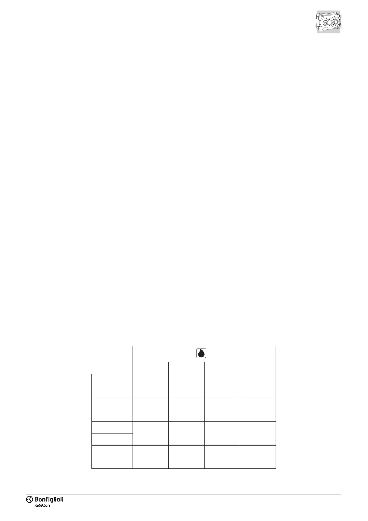
Controllare periodicamente il livello del
lubrificante effettuando la sostituzione
indicativamente agli intervalli riportati
nella tabella.
1.4 - MAINTENANCE
It is advisable to change the lubricant af-
ter the initial 300 hours of operation and
thoroughly clean the interior of the unit
with a suitable detergent.
Do not mix different types and/or brands
of oil.
Periodically check the oil level, and re-
place at the intervals given in the chart.
1.4 - WARTUNG
Es wird empfohlen, das Schmiermittel
erstmalig nach 300 Betriebsstunden zu
ersetzen, und den Getriebeinnenraum
mit einem angemessenen Reinigungs-
mittel sorgfältig zu säubern.
Schmieröle unterschiedlicher Art und/
oder Marke nicht mischen.
Regelmäßig den Schmiermittelstand
kontrollieren und nach den Angaben der
nachfolgenden Tabelle wechseln.
Temperatura olio / Oil temperature
Öltemperatur
Intervallo di lubrificazione / Oil change interval
Schmierintervall
[h]
[°C]
olio minerale / mineral oil
Mineralöl
olio sintetic / synthetic oil
Synthetiköl
t < 65 8000 25000
65<t<80 4000 15000
80<t<95 2000 12500

6
1.5 - STOCCAGGIO
Il corretto stoccaggio dei prodotti richie-
de l’esecuzione delle seguenti attività:
•Escludere aree all’aperto, zone espo-
ste alle intemperie o con eccessiva
umidità.
•Interporre sempre tra il pavimento ed i
prodotti, pianali lignei o di altra natura,
atti ad impedire il diretto contatto col
suolo.
•Per periodi di stoccaggio e soste pro-
lungate le superfici interessate agli ac-
coppiamenti quali flange, alberi e giunti
devono essere protette con idoneo pro-
dotto antiossidante (Tectile 506 EH o
equivalente).
In questo caso i riduttori dovranno es-
sere posizionati con il tappo di sfiato
nella posizione più alta e riempiti intera-
mente d’olio.
Prima della loro messa in servizio nei ri-
duttori dovrà essere ripristinata la corretta
quantità, e il tipo di lubrificante.
1.5 - STORAGE
Observe the following instructions to en-
sure correct storage of the products:
•Do not store outdoors, in areas ex-
posed to weather or with excessive
humidity.
•Always place boards, wood or other
material between the products and
the floor. The gearboxes should not
have direct contact with the floor.
•In case of long-term storage all ma-
chined surfaces such as flanges,
shafts and couplings must be coated
with a suitable rust inhibiting product
(Tectile 506 EH or equivalent). Fur-
thermore gear units must be placed
with the fill plug in the highest position
and filled up with oil. Before putting
the units into operation the appropri-
ate quantity, and type, of oil must be
restored.
1.5 - LAGERUNG
Befolgen Sie die nachstehenden Punkte
um eine korrekte Lagerung der Produkte
sicherzustellen:
•Die Getriebe dürfen nicht im Freien
sowie an Orten mit hoher Luftfeuchtig-
keit gelagert werden.
•Die Produkte nicht direkt auf den Bo-
den, sondern auf Paletten aus Holz
oder sonstigem Material stellen.
•Im Falle einer längeren Lagerung bzw.
bei längerem Stillstand müssen die Kon-
taktflächen wie Flansche, Wellen und
Kupplungen mit Antioxidationsmittel (Tec-
tile 506 EH oder gleichwertig) geschützt
werden. In diesem Fall müssen die Ge-
triebe so aufgestellt werden, dass die
Entlüftungsschraube an der höchsten Po-
sition ist. Anschließend muss das Getrie-
be vollständig mit Öl befüllt werden. Vor
Inbetriebnahme müssen die Getriebe
wieder mit der richtigen Schmiermittel-
menge und -art befüllt werden.
1.6 - CONDIZIONI DI FORNITURA
I riduttori vengono forniti come segue:
•già predisposti per essere installati
nella posizione di montaggio come
definito in fase di ordine;
•collaudati secondo specifiche interne;
•superfici di accoppiamento non verni-
ciate
•provvisti di bulloneria per la flangiatu-
ra del motore (se la predisposizione a
standard IEC è specificata).
1.6 - CONDITIONS OF SUPPLY
Gear units are supplied as follows:
•configured for installation in the
mounting position specified when or-
dering;
•tested to manufacturer specifications;
•mating machined surfaces come un-
painted;
•nuts and bolts for mounting motors
are provided if a flanged motor input
is specified.
1.6 - LIEFERBEDINGUNGEN
Die Getriebe werden wie folgt geliefert:
•ausgelegt für die Installation in der bei
Auftragserteilung angegebenen Ein-
baulage;
•abgenommen gemäß den firmeninter-
nen Spezifikationen;
•die Kontaktflächen sind nicht lackiert;
•Schrauben und Muttern für das An-
flanschen des Motors beiliegend (falls
die Auslegung nach IEC-Standard
spezifiziert ist).
1.7 - VERNICIATURA
La verniciatura esterna ed interna dei grup-
pi HDP delle grandezze da 60 a 90 è rea-
lizzata con polvere termoindurente a base
di resine epossidiche e poliestere dotata di
elevato indice di protezione dalla corrosio-
ne ed idonea all’installazione anche in am-
bienti esterni - colore grigio RAL 7042,
spessore complessivo 60-80 µm.
Può essere in seguito sovraverniciata con
vernici sintetiche.
I gruppi HDP 100 ... HDP 160 sono ver-
niciati a spruzzo con mano di primer
epossidico sia internamente che ester-
namente, seguita da una verniciatura
esterna a riduttore finito - colore grigio
RAL 7042. Spessore complessivo all'e-
sterno 130-180 µm. Spessore comples-
sivo all’interno 80-100 µm.
1.7 - PAINT COATING
HDP gearboxes in sizes 60 to 90 are ex-
ternally and internally painted in oven
hardened epoxy resin and polyester
powder paint that provides an excellent
level of protection against corrosion and
is suitable for outdoor installations.
The colour is RAL 7042 grey. A syn-
thetic top coat may also be applied.
HDP gearboxes in sizes 100 to 160 are
internally and externally spray painted
with an epoxy primer, and then finished
with an epoxy top coating for a total
thickness of 130-180 µm. The colour is
RAL 7042 grey.
Total thickness of internal coating is
80-100 µm.
1.7 - LACKIERUNG
Die Innen- und Außenlackierung der Ge-
triebe HDP der Baugrößen 60 bis 90 er-
folgt mit wärmehärtendem Pulver auf
Epoxydharz- und Polyester-Basis mit
hohem Korrosionsschutz und Eignung
auch für die Installation im Freien - Far-
be Grau RAL 7042. Kann nachträglich
mit Synthetiklacken überlackiert werden.
Die HDP Getriebe der Baugrößen 100
bis 160 sind innen und außen mit
Epoxydharzgrundierung spritzbeschic-
htet und nachträglich, nach der Montage
von Getrieben, mit Epoxydharzanstrich
überlackiert. Gesamtstärke der Außen-
schicht 130–180 µm. Farbe Grau RAL
7042. Gesamtstärke der Innenschicht
80–100 µm.

7
1.8 - FATTORE DI SERVIZIO
I fattori di servizio elencati qui di seguito
sono valori empirici basati su specifiche
emesse dalle Norme ISO e AGMA e dal-
la conoscenza maturata dal costruttore
in lunghi anni di attività nell’industria.
Essi sono applicabili per macchine pro-
gettate e realizzate secondo lo stato del-
l’arte e operanti in condizioni di funzio-
namento normali.
1.8 - SERVICE FACTOR
Service factors listed here under are
empirical values based on AGMA and
ISO specifications as well as our experi-
ence for use in common applications.
They apply for state of the art-designed
driven machines and normal operating
conditions.
1.8 - BETRIEBSFAKTOR
Die nachstehend aufgeführten Betriebs-
faktoren sind empirische Werte, die auf
Spezifikationen der ISO- und AGMA-Nor-
men und auf der langjährigen Erfahrung
des Herstellers in der Industrie beruhen.
Sie gelten für Maschinen, die nach dem
Stand der Technik konzipiert wurden und
unter normalen Betriebsbedingungen ar-
beiten.
Applicazione Application Applikation
£10 > 10
ore/giorno
hours/day
Std./Tag
ore/giorno
hours/day
Std./Tag
AGITATORI, MESCOLATORI AGITATORS, MIXERS RÜHRWERKE, MISCHER
Liquidi a densità costante Pure liquids Flüssigkeiten mit konstanter Dichte 1.25 1.50
Liquidi con solidi in sospensione Liquids and solids Flüssigkeiten mit Schwebstoffen 1.25 1.50
Liquidi a densità variabile Liquids - variable density Flüssigkeiten mit variabler Dichte 1.50 1.75
SOFFIANTI BLOWERS GEBLÄSE
Centrifughe Centrifugal Zentrifugalgebläse 1.00 1.25
A lobi Lobe Drehkolbengebläse 1.25 1.50
A palette Vane Drehschiebergebläse 1.25 1.50
CHIARIFICATORI CLARIFIERS KLÄRBECKEN 1.00 1.25
MACCHINE PER LAVORAZIONE
DELL'ARGILLA
CLAY WORKING MACHINERY MASCHINEN FÜR DIE TONBEARBEITUNG
Presse per laterizi Brick press Ziegelpressen 1.75 2.00
Presse per formatura piastrelle Briquette machine Fliesenpressen 1.75 2.00
Impastatrici Pug mill Knetmaschinen 1.25 1.50
COMPATTATORI COMPACTORS KOMPAKTOREN 2.00 2.00
COMPRESSORI COMPRESSORS VERDICHTER
Centrifughi Centrifugal Zentrifugalverdichter 1.25 1.50
A lobi Lobe Drehkolbenverdichter 1.25 1.50
Alternativi, pluricilindrici Reciprocating, multi-cylinder Mehrzylinder-Hubkolbenverdichter 1.50 1.75
Alternativi, monocilindrici Reciprocating, single-cylinder Einzelzylinder-Hubkolbenverdichter 1.75 2.00
TRASPORTATORI - USO GENERALE CONVEYORS - GENERAL PURPOSE FÖRDERER - ALLGEMEINE VERWENDUNG
Carico uniformemente distribuito Uniformly loaded or fed Gleichmäßig verteilte Last 1.15 1.25
- Servizio pesante - Heavy duty - Schwerer Betrieb
Carico non uniformemente distribuito Not uniformly fed Ungleichmäßig verteilte Last 1.25 1.50
- Alternativi o a scosse - Reciprocating or shaker - Schwing- oder Rüttelförderer 1.75 2.00
GRU (*) CRANES (*) KRANE (*)
Bacino di carenaggio Dry dock Reparaturdock
Paranco principale Main hoist Hauptrollenzug 2.50 2.50
Paranco ausiliario Auxiliary hoist Hilfsrollenzug 2.50 3.00
Paranco a braccio Boom hoist Armrollenzug 2.50 3.00
Azionamento rotazione Slewing Drive Drehantrieb 2.50 3.00
Azionamento traslazione Traction Drive Fahrantrieb 3.00 3.00
Carrello Trolley Drive Wagen
Traslazione portale Gantry Drive Fahrantrieb Kranportal 3.00 3.00
Azionamento traslazione Traction Drive Fahrantrieb 2.00 2.00
Impiego industriale Industrial duty Industrieller Einsatz
Paranco principale Main hoist Hauptrollenzug 2.50 3.00
Paranco ausiliario Auxiliary hoist Hilfsrollenzug 2.50 3.00
Ponte e Bridge and Brückenkran 3.00 3.00
Traslazione carrello Trolley travel Fahrantrieb Kranwagen 3.00 3.00
FRANTUMATORI CRUSHER BRECHER
Pietre o minerali Stone or ore Steine oder Minerale 2.00 2.00
(*) - L’indicazione del fattore di servizio in fun-
zione della classificazione FEM è disponibile
su richiesta. Consultare il Servizio Tecnico
Bonfiglioli.
- Argani per sollevamento di persone: i valori
in tabella non sono applicabili. Consultare
il Servizio Tecnico Bonfiglioli.
(*) - Indication of service factor based on FEM
1.001 classification available upon request.
Consult factory.
- Hoists for passengers lift: charted values
not applicable. Consult factory.
(*) - Die Angabe des Betriebsfaktors in Abhän-
gigkeit von der FEM-Einstufung ist auf Anfra-
ge verfügbar. Bitte wenden Sie sich an den
technischen Kundendienst von Bonfiglioli.
- Aufzugswinden für Personenaufzüge: Die
Tabellenwerte sind nicht anwendbar bei
Aufzugswinden von Personenaufzügen. Bitte
wenden Sie sich an den technischen Kun-
dendienst von Bonfiglioli.

8
Applicazione Application Applikation
£10 >10
ore/giorno
hours/day
Std./Tag
ore/giorno
hours/day
Std./Tag
DRAGHE DREDGES SCHWIMMBAGGER
Trasportatori Conveyors Förderer 1.25 1.50
Azionamenti teste portafrese Cutter head drives Antriebe Fräsköpfe 2.00 2.00
Vagli Screen drives Siebe 1.75 2.00
Accatastatori Stackers Stapler 1.25 1.50
Argani Winches Aufzugswinden 1.25 1.50
ELEVATORI ELEVATORS ELEVATOREN
A tazze Bucket Becherwerke 1.25 1.50
A scarico centrifugo Centrifugal discharge Mit Zentrifugalentleerung 1.15 1.25
Scale mobili Escalators Rolltreppen 1.15 1.25
Carico Freight Beladung 1.25 1.50
Scarico per gravità Gravity discharge Schwerkraftentleerung 1.15 1.25
ESTRUSORI EXTRUDERS STRANGPRESSEN
Generalità General Allgemein 1.50 1.50
Plastica Plastics Kunststoff
Funzionamento a velocità variabile Variable speed drive Betrieb bei variabler Drehzahl 1.50 1.50
Funzionamento a velocità fissa Fixed speed drive Betrieb bei unveränderlicher Drehzahl 1.75 1.75
Gomma Rubber Gummi
Funzionamento vite continuo Continuous screw operation Dauer-Schneckenbetrieb 1.75 1.75
Funzionamento vite intermittente Intermittent screw operation Aussetzender Schneckenbetrieb 1.75 1.75
VENTILATORI FANS VENTILATOREN
A centrifuga Centrifugal Zentrifugalventilatoren 1.00 1.25
Torri di raffreddamento Cooling towers Kühltürme 2.00 2.00
Tiraggio forzato Forced draft Druckbelüftet 1.25 1.25
Tiraggio indotto Induced draft Saugzug-Gegenstrom 1.50 1.50
Industriali e ad uso minerario Industrial and mine Industriell und Verwendung Untertage 1.50 1.50
ALIMENTATORI FEEDERS BESCHICKER
A piastre Apron Plattenbandbeschicker 1.25 1.50
A cinghia Belt Gurtbeschicker 1.15 1.50
A tavola Disc Tischbeschicker 1.00 1.25
Alternativi Reciprocating Schwenkbeschicker 1.75 2.00
A vite Screw Schneckenbeschicker 1.25 1.50
INDUSTRIA ALIMENTARE FOOD INDUSTRY NAHRUNGSMITTELINDUSTRIE
Impastatrici Dough mixer Knetmaschinen 1.25 1.50
Tritacarne Meat grinders Fleischwölfe 1.25 1.50
Affettatrici Slicers Aufschnittmaschinen 1.25 1.50
GENERATORI DI CORRENTE GENERATORS AND EXCITERS STROMERZEUGER 1.00 1.25
MOLINI A MARTELLO HAMMER MILLS HAMMERMÜHLEN 1.75 2.00
ARGANI (*) HOISTS (*) AUFZUGSWINDEN (*)
Servizio pesante Heavy duty Schwerer Betrieb 1.75 2.00
Servizio medio Medium duty Mittlerer Betrieb 1.25 1.50
Argani a cassetta Skip hoist Schrägaufzüge 1.25 1.50
INDUSTRIA DEL LEGNO LUMBER INDUSTRY HOLZINDUSTRIE
Scortecciatrici - avanzamento del mandrino Barkers - spindle feed Entrindungsmaschinen - Spindelvorschub 1.25 1.50
Azionamento principale Main drive Hauptantrieb 1.75 1.75
Trasportatori - bruciatori Conveyors - burner Förderer - Brenner 1.25 1.50
Servizio principale o pesante Main or heavy duty Haupt- oder schwerer Betrieb 1.50 1.50
Tronco principale Main log Hauptstamm 1.75 2.00
Risegatura, giostra Re-saw, merry-go-round Sägearbeiten, Karussell 1.25 1.50
Trasportatori Conveyors Förderer
Lastra Slab Platte 1.75 2.00
Trasferimento Transfer Transfer 1.25 1.50
Catene Chains Ketten
Pavimento Floor Boden 1.50 1.50
Non stagionato Green Grünes Holz 1.50 1.75
(*) - L’indicazione del fattore di servizio in fun-
zione della classificazione FEM è disponibile
su richiesta. Consultare il Servizio Tecnico
Bonfiglioli.
- Argani per sollevamento di persone: i valori
in tabella non sono applicabili. Consultare
il Servizio Tecnico Bonfiglioli.
(*) - Indication of service factor based on FEM
1.001 classification available upon request.
Consult factory.
- Hoists for passengers lift: charted values
not applicable. Consult factory.
(*) - Die Angabe des Betriebsfaktors in Abhän-
gigkeit von der FEM-Einstufung ist auf Anfra-
ge verfügbar. Bitte wenden Sie sich an den
technischen Kundendienst von Bonfiglioli.
- Aufzugswinden für Personenaufzüge: Die
Tabellenwerte sind nicht anwendbar bei
Aufzugswinden von Personenaufzügen. Bitte
wenden Sie sich an den technischen Kun-
dendienst von Bonfiglioli.

9
Applicazione Application Applikation
£10 > 10
ore/giorno
hours/day
Std./Tag
ore/giorno
hours/day
Std./Tag
Segatrici Cut-off saws Handsägen
Catena Chain Kette 1.50 1.75
Trascinamento Drag Mitnehmer 1.50 1.75
Cilindri di scortecciatura Debarking drums Schälzylinder 1.75 2.00
Avanzamenti Feeds Vorschübe
Rifilatrice Edger Beschneidemaschine 1.25 1.50
Lame multiple Gang Mehrfachklingen 1.75 1.75
Taglierina Trimmer Cutter 1.25 1.50
Tronchi in pila Log deck Gestapelte Stämme 1.75 1.75
Convogliatori di tronchi - rampa - a ruote Log hauls - incline - weel type Stammförderer - Rampe - mit Rädern 1.75 1.75
Dispositivi ribaltamento tronchi Log turning devices Stamm-Kippvorrichtungen 1.75 1.75
Avanzamento piallatrice Planer feed Vorschub Hobelmaschine 1.25 1.50
Paranchi ribaltamento tronchi Planer tilting hoists Stamm-Kipprollenzüge 1.50 1.50
A rulli Rolls - live-off brg. - roll cases Mit Rollen 1.75 1.75
Tavola di selezione Sorting table Selektiertisch 1.25 1.50
Paranco con piano ribaltabile Tipple hoist Rollenzug mit Kipptisch 1.25 1.50
Trasbordatori Transfers Verschiebebühnen
Catena Chain Kette 1.50 1.75
Vie di corsa Craneways Laufbahnen 1.50 1.75
Azionamento vassoi Tray drives Tablettantrieb 1.25 1.50
Azionamento torni piallacci Veneer lathe drives Antrieb Furnierdrehmaschinen 1.25 1.50
STABILIMENTI METALLURGICI METAL MILLS METALLURGISCHE WERKE
Spintori lastre Slab pushers Plattenschieber 1.50 1.50
Trance Shears Scheren 2.00 2.00
Trafilatura Wire drawing Drahtziehmaschinen 1.25 1.50
Bobinatrice Wire winding machine Spulmaschine 1.50 1.50
MULINI, TIPO ROTANTE MILLS, ROTARY TYPE DREHMÜHLEN
Palla e barra Ball and rod Kugel- und Stabmühlen 2.00 2.00
Corona dentata cilindrica Spur ring gear Zylindrischer Zahnkranz 2.00 2.00
Corona dentata elicoidale Helical ring gear Schrauben-Zahnkranz 1.50 1.50
Collegamento diretto Direct connected Direktverbindung 2.00 2.00
Forni da cemento Cement kilns Zementöfen 1.50 1.50
Essiccatori e refrigeratori Dryers and coolers Trockner und Kühler 1.50 1.50
MESCOLATORI MIXERS MISCHER
Calcestruzzo Concrete Beton 1.50 1.75
CARTIERE PAPER MILLS PAPIERFABRIKEN
Agitatore (impastatore) Agitator (mixer) Rührwerk (Kneter) 1.50 1.50
Agitatore per liscivia pura Agitator for pure liquors Rührwerk für reine Lauge 1.25 1.25
Cilindri di scortecciatura Barking drums Schälzylinder 2.00 2.00
Scortecciatrici - meccaniche Barkers - mechanical Entrindungsmaschinen - mechanisch 2.00 2.00
Raffinatore Beater Refiner 1.50 1.50
Sfilacciatore Breaker stack Reißwolf 1.25 1.25
Calandra Calendar Kalander 1.25 1.25
Sminuzzatrice Chipper Shredder 2.00 2.00
Alimentatore trucioli Chip feeder Spänebeschicker 1.50 1.50
Cilindri di patinatura Coating rolls Patinierzylinder 1.25 1.25
Trasportatori Conveyors Förderer
Truciolo, corteccia, sostanze chimiche Chip, bark, chemical Späne, Rinde, Chemikalien 1.25 1.25
Tronco (tavola inclusa) Log (including slab) Stamm (einschl, Tafel) 2.00 2.00
Presse manicotto Couch rolls Muffenpressen 1.25 1.25
Fresa Cutter Fräse 2.00 2.00
Stampi cilindrici Cylinder molds Zylindrische Werkzeuge 1.25 1.25
Essiccatori Dryers Trockner
Macchina continua Paper machine Papiermaschine 1.25 1.25
Tipo a convogliatori Conveyors type Mit Förderern 1.25 1.25
Goffratrice Embosser Gaufriermaschine 1.25 1.25
Estrusore Extruder Strangpresse 1.50 1.50
Macchina per raffinare la polpa Jordan Halbstoff-Refiner 1.50 1.50
Azionamento forno Kiln drive Ofenantrieb 1.50 1.50
Rotoli di carta Paper rolls Papierrollen 1.25 1.25
Piatto Platter Teller 1.50 1.50
Presse - feltro e aspirazione Presses - felt and suction Pressen - Filz und Absaugung 1.25 1.25
Impastatrici Pulper Knetmaschinen 2.00 2.00
Pompe - a vuoto Pumps - vacuum Vakuumpumpen 1.50 1.50

10
Applicazione Application Applikation
£10 > 10
ore/giorno
hours/day
Std./Tag
ore/giorno
hours/day
Std./Tag
Bobina (tipo superficiale) Reel (surface type) Flächenspule 1.25 1.25
Setacci Screens Siebe
Trucioli Chip Späne 1.50 1.50
Rotanti Rotary Drehsiebe 1.50 1.50
Vibranti Vibrating Rüttelsiebe 2.00 2.00
Pressa a misura Size press Leimpresse 1.25 1.25
Supercalandra Super calendar Superkalander 1.25 1.25
Addensatore (motore CA) Thickener (AC motor) Eindicker (AC-Motor) 1.50 1.50
Addensatore (motore CC) Thickener (DC motor) Eindicker (DC-Motor) 1.25 1.25
Lavatrice (motore CA) Washer (AC motor) Waschmaschine (AC-Motor) 1.50 1.50
Lavatrice (motore CC) Washer (DC motor) Waschmaschine (DC-Motor) 1.25 1.25
Supporto di avvolgimento e svolgimento Wind and unwind stand Auf- und Abwickelhalter 1.25 1.50
Incannatoi (tipo superficiale) Winders (surface type) Flächenspulmaschinen 1.25 1.25
Essiccatoi Yankee Yankee dryers Yankee-Trockner 1.25 1.25
INDUSTRIA DELLA PLASTICA PLASTICS INDUSTRY KUNSTSTOFFINDUSTRIE
Impastatori lotti Batch mixers Chargenkneter 1.75 1.75
Miscelatori continui Continuous mixers Dauermischer 1.50 1.50
Impianto di mescolatura Compounding mill Mischanlagen 1.25 1.25
Calandre Calendars Kalander 1.50 1.50
Lavorazione secondaria Secondary processing Sekundärbearbeitung
Impianti di soffiatura Blow molders Gebläseanlagen 1.50 1.50
Rivestimento Coating Beschichtung 1.25 1.25
Pellicola Film Folien 1.25 1.25
Pre-masticatori Pre-plasticizers Vor-Zerkleinerer 1.50 1.50
Barre Rods Stäbe 1.25 1.25
Lastra Sheet Platten 1.25 1.25
Tubi Tubing Rohre 1.25 1.50
POMPE PUMPS PUMPEN
Centrifughe Centrifugal Kreiselpumpen 1.15 1.25
A moto alternativo Reciprocating Hubkolbenpumpen
A effetto semplice, tre o più cilindri Single acting, three or more cylinders Einfachwirkend, drei oder mehr Zylinder 1.25 1.50
A doppio effetto, due o più cilindri Double acting, two or more cylinders Doppeltwirkend, zwei oder mehr Zylinder 1.25 1.50
Rotanti Rotary Drehpumpen
Tipo a ingranaggi Gear type Zahnradpumpen 1.15 1.25
A lobi Lobe Drehkolbenpumpen 1.15 1.25
A pale Vane Flügelpumpen 1.15 1.25
INDUSTRIA DELLA GOMMA RUBBER INDUSTRY GUMMIINDUSTRIE
Impastatori interni intensivi Intensive internal mixer Interne Intensivkneter
Impastatori lotti Batch mixers Chargenkneter 1.75 1.75
Miscelatori continui Continuous mixers Dauermischer 1.50 1.50
Raffinatore - due cilindri Refiner - two rolls Refiner - zwei Zylinder 1.50 1.50
Calandre Calendars Kalander 1.50 1.50
MOLAZZA PER SABBIA SAND MULLER MAHLGANG FÜR SAND 1.25 1.50
DISPOSITIVI SMALTIMENTO LIQUAMI SEWAGE DISPOSAL EQUIPMENT VORRICHTUNGEN FÜR DIE
ABWASSERENTSORGUNG
Aeratori Aerators Belüfter 2.00 2.00
Alimentatori sostanze chimiche Chemical feeders Beschicker von chemischen Substanzen 1.25 1.25
Vagli di disidratazione Dewatering screens Dehydratisierungssiebe 1.50 1.50
Frangi scorie Scum breakers Schlackenbrecher 1.50 1.50
Mescolatori lenti o rapidi Slow or rapid mixers Langsame oder schnelle Mischer 1.50 1.50
Collettori di fanghi Sludge collectors Schlammsammler 1.25 1.25
Addensatori Thickeners Schlammverdichter 1.50 1.50
Filtri a vuoto Vacuum filters Vakuumfilter 1.50 1.50
SETACCI SCREENS SIEBE
Lavaggio aria Air washing Luftwäsche 1.00 1.25
Rotanti - pietra o ghiaia Rotary - stone or gravel Drehsiebe - Stein oder Kies 1.25 1.50
Mobili entrata acqua Travelling water intake Mobile Siebe Wassereintritt 1.00 1.25
INDUSTRIA DELLO ZUCCHERO SUGAR INDUSTRY ZUCKERINDUSTRIE
Pelabarbabietole Beet slicer Rübenschälmaschinen 2.00 2.00
Lame per canne Cane knives Zuckerrohrmesser 1.50 1.50
Frantoi Crushers Ölmühlen 1.50 1.50
Mulini (estremità a bassa velocità) Mills (low speed end) Mühlen (mit niedriger Geschwindigkeit) 1.75 1.75
MACCHINARIO TESSILE TEXTILE MACHINERY TEXTILMASCHINEN 1.25 1.50
11
1.9 - LUBRIFICAZIONE
Gli organi interni dei riduttori HDP sono
lubrificati con un sistema misto di immer-
sione e sbattimento dell’olio. Per velocità
di comando inferiori a 500 min-1 o supe-
riori a 1500 min-1, consultare preventiva-
mente il Servizio Tecnico di Bonfiglioli.
Nella posizione di montaggio V5 i cusci-
netti superiori dei gruppi da HDP 60 a
HDP 90 sono lubrificati con grasso e do-
tati di anello di ritegno Nilos, salvo che
in fase d’ordine sia specificato un siste-
ma di lubrificazione forzato tramite pom-
pa meccanica (variante opzionale OP1,
OP2) o motopompa (opzione MOP).
I riduttori HDP delle grandezze da 100 a
160 qualora siano richiesti nella posizio-
ne di montaggio V5, con albero lento
verticale, richiedono invariabilmente la
specifica di uno dei sistemi di lubrifica-
zione forzata sopra menzionati, da sele-
zionare in funzione della velocità e/o
delle condizioni di esercizio.
I riduttori sono forniti privi di lubrificante
e sarà cura del Cliente immettere, prima
della messa in opera, la quantità di olio
appropriata.
Le quantità di lubrificante riportate in
tabella sono indicative. Per il corretto
riempimento si dovrà fare riferimento
alla mezzeria del tappo, o dell’astina
di livello, se presente.
Rispetto a questa condizione la quan-
tità di lubrificante riportata in tabella
può presentare scostamenti, occasio-
nalmente anche rilevanti, in funzione
del rapporto o della particolare ese-
cuzione del prodotto.
1.9 - LUBRICATION
The internal parts of HDP gearboxes are
lubricated with a mixed immersion and
splash system. Should the drive speed
be lower than 500 min-1 or greater than
1500 min-1, please contact Bonfiglioli
Technical Service for advise.
In mounting position V5, the top bear-
ings in gearbox sizes HDP 60 to HDP 90
are pre-lubricated with grease and fitted
with Nilos seals, unless the order speci-
fies a forced lubrication system with me-
chanical pump (optional variants OP1,
OP2) or electric pump (option MOP).
If HDP 100 to 160 gearboxes have to be
installed in mounting position V5, with
the output shaft vertical, one of the
above mentioned forced lubrication sys-
tems must be specified. The actual sys-
tem should be selected on the basis of
speed and/or operating conditions.
These gearboxes are supplied without
lubricant. It is the customer’s responsi-
bility to fill them with the appropriate
amount of oil before start-up.
The amounts of lubricant given in the
chart are indicative. Use the plug
hole centre line or the dipstick, if pro-
vided, for correct filling. The amount
of lubricant given in the chart may
vary, sometimes substantially, de-
pending on the ratio or particular ex-
ecution of the product.
1.9 - SCHMIERUNG
Die Innenteile der Getriebe HDP werden
mit einem gemischten System der Tauch-
und Ölspritzschmierung geschmiert.
Wenn die Eingangsdrehzahl niedriger als
500 min-1 oder höher als 1500 min-1,kon
-
taktieren Sie bitte den Technischen Servi-
ce von Bonfiglioli.
In der Einbaulage V5 werden die oberen
Lager der Gruppen HDP 60 bis HDP 90
mit Fett geschmiert und mit einem Ni-
los-Ring versehen, es sei denn, dass bei
Auftragserteilung ein Zwangsschmiersys-
tem mittels mechanischer Pumpe (optio-
nale Variante OP1, OP2) oder Motor-
pumpe (Option MOP) bestellt wurde.
Bei Bestellung der Getriebe für die Ein-
baulage V5 (vertikale Abtriebswelle) müs-
sen die Getriebe HDP der Baugrößen
100 bis 160 unbedingt mit einer der oben
genannten Zwangsschmiersysteme, das
aufgrund der Drehzahl und/oder der Be-
triebsbedingungen auszuwählen ist, aus-
gerüstet werden. Die Getriebe werden
ohne Schmiermittel geliefert, und der
Kunde muss vor Inbetriebnahme die kor-
rekte Ölmenge einfüllen.
Die in der Tabelle angegebenen
Schmiermittelmengen sind Richtwer-
te. Für die korrekte Füllung muss auf
die Mittellinie des Öleinfüllstutzens
oder des Ölstabs (sofern vorhanden)
Bezug genommen werden. Je nach
Übersetzungsverhältnis oder je nach
Ausführung des Produkts können die
tatsächlichen Füllmengen unter Um-
ständen auch stark von den Tabellen-
werten abweichen.
oil
[l
]
B3 B6 B7 V5
HDP 60 2 10 14.8 14.6 16
HDP 60 3
HDP 70 2 11 16 15 17
HDP 70 3
HDP 80 2 16 24 24 26
HDP 80 3
HDP 90 2 23 34 33 37
HDP 90 3

12
Nei seguenti casi è necessario prevede-
re il pre-riscaldamento dell’olio attraver-
so un’opportuna resistenza elettrica (va-
riante opzionale HE):
•funzionamento a temperature inferiori
a 0°C
•avviamento di riduttori lubrificati ad
immersione e sbattimento qualora la
temperatura ambiente minima non sia
superiore di almeno 10°C al punto di
scorrimento dell’olio
•avviamento di riduttori con dispositivi di
lubrificazione forzata (varianti OP1, OP2,
MOP), quando la viscosità dell’olio è su-
periore a 1800 cst. In funzione del lubrifi-
cante utilizzato questo valore si riscontra
indicativamente a temperature ambiente
comprese fra 10°C e 20°C.
Lubricant must be pre-heated through
the appropriate electric resistance (HE
option) in the following cases:
•operation at ambient temperatures
lower than 0°C
•operation of gear units lubricated by
oil immersion and splashing when the
minimum ambient temperature ex-
ceeds the pour point of lubricant by
less than 10°C
•Upon starting up gear units with
forced lubrication systems (options
OP1, OP2 or MOP) if the oil viscosity
exceeds 1800 cst. Depending of the
type of lubricant used, this value may
be produced with ambient tempera-
tures between 10°C and 20°C approx.
In folgenden Fällen muss das Öl mit ei-
nem geeigneten elektrischen Heizwider-
stand (optionale Variante HE) vorge-
wärmt werden:
•Betrieb bei Temperaturen unter 0°C
•Anfahren von Getrieben mit Tauch- und
Ölspritzschmierung, wenn die niedrigste
Umgebungstemperatur mehr als 10°
unter dem Fließpunkt des Öls liegt
•Anfahren von Getrieben mit Zwangs-
schmierung (Varianten OP1, OP2,
MOP), wenn die Viskosität des Öls
über 1800 cSt liegt. Je nach verwende-
tem Schmiermittel tritt dieser Wert un-
gefähr bei Umgebungstemperaturen
zwischen 10°C und 20°C auf.
Lubrificante / Lubricant / Schmiermittel Viscosità cinematica a 40°C / Kinematic viscosity at 40°C / Kinematische Viskosität 40°C
[cSt]
ISO VG 220 ISO VG 320 ISO VG 460
Olio minerale EP
Mineral Oil (EP additives)
Mineralöl EP
Tamb 0°C ... 20°C 10°C ... 40°C 20°C ... 50°C
Olio sintetico
Synthetic oil
Synthetiköl
Tamb 0°C ... 30°C 10°C ... 50°C —
oil
[l
]
B3 B6 B7 V5
HDP 100 2 27 61 49 51
HDP 100 3 32 70 56 58
HDP 100 4 34
HDP 110 2 27 61 49 51
HDP 110 3 32 70 56 58
HDP 110 4
HDP 120 2 35 83 64 68
HDP 120 3 45 96 74 79
HDP 120 4
HDP 130 2 57 154 119 128
HDP 130 3 86 181 140 150
HDP 130 4
HDP 140 2 76 163 126 115
HDP 140 3 89 191 147 135
HDP 140 4 88
HDP 150 2 109 244 189 173
HDP 150 3 125 281 217 199
HDP 150 4
HDP 160 2 118 264 204 187
HDP 160 3 135 303 234 214
HDP 160 4

13
2 - SELEZIONE DEL RIDUTTORE
La selezione ottimale della trasmissione
può essere condotta solo previa la piena
conoscenza delle condizioni applicative,
sia di natura funzionale, che ambientale.
A garanzia di un corretto dimensiona-
mento del prodotto, è vivamente consi-
gliato ricorrere all'esperienza e alla spe-
cifica conoscenza del Servizio Tecnico
di Bonfiglioli.
2.1 - DIMENSIONAMENTO
1. Determinare il rapporto di trasmissio-
ne:
2. Calcolare la potenza richiesta Pr1 al-
l’albero veloce del riduttore:
3. Determinare il fattore di servizio fsappli-
cabile e il fattore correttivo dipendente
dal tipo di organo motore fm:
4. Dalle tabelle dati tecnici selezionare il
riduttore con rapporto di trasmissione
più prossimo a quello calcolato e ca-
ratterizzato da una potenza nominale
Pn1, tale che:
2 - SELECTING THE GEAR UNIT
The selection of the drive unit can only
be optimized upon knowing both the en-
gineering and the environmental condi-
tions the gearbox will operate into.
For a safe selection it is strongly recom-
mended to rely on the long time experi-
ence of the Bonfiglioli Technical Service
Dept.
2.1 - ENGINEERING SELECTION
1. First determine the gear ratio:
2. Calculate the power Pr1 required at
the input shaft:
3. Determine the applicable service fac-
tor fsand the adjusting factor fmde-
pending on prime mover:
4. Use the rating charts to select the
gear unit with the gear ratio nearest
to that calculated, and with a rated
power Pn1, so that:
2 - WAHL DES GETRIEBES
Eine optimale Wahl der Uebertragung
kann durch eine vollständige Bekannt-
schaft von allen Anwendungsbedingungen
sowohl die zweckmäßige als auch die
Umweltbedingungen ausgeführt werden.
Um eine richtige Bemessung zu gewähren,
empfehlen wir Sie, an die Dienstleistungs-
service von der Bonfiglioli zu wenden.
2.1 - BEMESSUNG
1. Die Übersetzung ermitteln:
2. Benötigte Leistung Pr1 an der An-
triebswelle des Getriebes berechnen:
3. Bestimmen Sie den geeigneten Be-
triebsfaktor fsund den Korrekturfak-
tor fmin Abhängigkeit von der An-
triebsmaschine:
4. Aus den technischen Datentabellen
ein Getriebe aussuchen, dessen
Übersetzungsverhältnis dem berech-
neten am nächsten kommt, und des-
sen Nennleistung Pn1, die folgende
Bedingung ermöglicht:
in
n
=1
2
PMrxn
9550 x
r1 22
=h
h
2x 0.96
3x 0.94
4x 0.92
Pn1 ³Pr1 ´fs´fm
fm
Motore elettrico
Motore idraulico
Turbina
Electric motor
Hydraulic motor
Turbine
Elektromotor
Hydraulikmotor
Turbine
1.00
Motore a combustione
interna pluricilindrico
Multi-cylinder internal
combustion engine
Mehrzylinder-Verbrennungs-
motor 1.25
Motore a combustione
interna monocilindrico
Single cylinder internal
combustion engine
Einzelzylinder-Verbren-
nungsmotor 1.50

14
Picchi/ora / Peaks/hour
Spitzenwerte/Stunde
fp
1 2 ... 10 11 ... 50 51 ... 100 > 100
Tipo di moto
Drive
Bewegungsart
Direzione costante
Constant direction
Konstante Richtung
2.0 1.6 1.3 1.1 1.0
Inversioni di moto
Reversals
Reversierbetrieb
1.4 1.1 0.9 0.8 0.7
Se la condizione suddetta non fosse ve-
rificata prevedere l’installazione di un di-
spositivo limitatore di coppia, oppure
considerare la selezione di un riduttore
di taglia superiore.
For configuration S (output shaft with
shrink disc), use the following values to
verify applicability.
Für die Konfiguration S (Abtriebswelle
mit Schrumpfverbindung) die Überprü-
fung unter Berücksichtigung folgender
Werte ausführen.
2.2.2 - ABBINAMENTO MOTORE
Per il riduttore selezionato verificare la
disponibilità della relativa flangia di ac-
coppiamento nella sezione 3.5.
La normalizzazione tipica dei motori
elettrici può portare a selezionare un
motore caratterizzato da potenza di tar-
ga superiore, anche considerevolmente,
alla potenza nominale Pn1 del riduttore
che si è dimensionato. Verificare che in
nessuna condizione del ciclo di lavoro la
maggiore potenza erogabile dal motore
elettrico sia effettivamente sviluppata. In
presenza di dati di calcolo incerti, o di
dubbi sull’effettivo diagramma di carico
dell’applicazione è consigliabile installa-
re un dispositivo limitatore di coppia.
2.2.2 - MOTOR MOUNTING
Verify that the appropriate motor
adapter is available for the selected
gear unit. See section 3.5.
Because of standardisation, the rated
power of the electric motor selected
might be greater than power Pr1 actually
requested by the application. Make sure
that the electric motor will never develop
the extra power at any stage of the oper-
ating cycle. If you have any doubts
about the validity of the application data,
or uncertainty concerning the actual load
pattern, install a torque limiting device or
proportionally revise the applicable ser-
vice factor.
2.2.2 - MOTORZUSAMMENSTELLUNG
Für das gewählte Getriebe im Abschnitt
3.5 die Verfügbarkeit des entsprechenden
Kupplungsflansches überprüfen.
Aufgrund der Normierung von Elektromo-
toren kann es dazu kommen, dass ein
Motor gewählt wird, dessen Nennleistung
Pn1 größer als die erforderliche Leistung
Pr1 für die Anwendung ist. Es muss si-
chergestellt werden, dass diese über-
schüssige Leistung zu keiner Zeit an das
Getriebe abgegeben wird. Sollten Zweifel
oder Unsicherheiten bezüglich der Bela-
stungs- oder Anwendungsdaten beste-
hen, empfiehlt sich die Installation eines
Drehmomentbegrenzers.
2.2 - VERIFICHE
2.2.1 - CARICHI IMPULSIVI
In presenza di cicli di lavoro intermittenti,
o caratterizzati da urti, avviamenti a pie-
no carico o elevati carichi inerziali, per il
valore di coppia istantanea Mpsviluppa-
ta nel ciclo di funzionamento si deve ve-
rificare la seguente condizione:
2.2 - VERIFICATIONS
2.2.1 - SHOCK LOADING
For intermittent duty, impact/shock loading
applications or start-ups under full load or
with high inertial loads, make sure the fol-
lowing condition is satisfied for momentary
peak torque Mpgenerated during the op-
erating cycle:
2.2 - KONTROLLEN
2.2.1 - STOSSBELASTUNG
Stellen Sie sicher, dass im Fall von ausset-
zenden Arbeitszyklen, oder bei Arbeitszyklen
die durch Stöße, Anlaufen unter Volllast oder
durch hohe Trägheitskräfte gekennzeichnet
sind, folgende Bedingung, für kurzzeitige
Spitzenmomente Mpdie während des Be-
triebs erzeugt werden, eingehalten wird:
Mp£Mn2 ´fp
Per la configurazione S (albero lento
con calettatore) eseguire la verifica con-
siderando i seguenti valori.
If the above condition is not satisfied, con-
sider installing a torque limiter or selecting
a gear unit of the next size up.
Wenn die oben genannte Bedingung
nicht erfüllt wird, muss ein Drehmoment-
begrenzer installiert oder ein größeres
Getriebe gewählt werden.
Picchi/ora / Peaks/hour
Spitzenwerte/Stunde
fp
1 ... 50 51 ... 100 > 100
Tipo di moto
Drive
Bewegungsart
Direzione costante
Constant direction
Konstante Richtung
1.3 1.1 1.0
1.1 (HDP 80)
Inversioni di moto
Reversals
Reversierbetrieb
0.9 0.8 0.7
0.8 (HDP 80)
15
2.2.4 - FORZA RISULTANTE
SULL’ALBERO
Organi di trasmissione calettati sugli alberi
di ingresso e/o di uscita del riduttore ge-
nerano forze la cui risultante agisce in
senso radiale sull’albero stesso.
L’entità di questi carichi deve essere
compatibile con la capacità di sopporta-
zione del sistema albero-cuscinetti del
riduttore, in particolare il valore assoluto
del carico applicato (Rc1 per albero di in-
gresso, Rc2 per albero di uscita) deve
essere inferiore al valore nominale (Rx1
per albero di ingresso, Rx2 per albero di
uscita) riportato nelle tabelle dati tecnici.
Il procedimento descritto si applica indiffe-
rentemente all’albero veloce o all’albero
lento avendo l’avvertenza di utilizzare i co-
efficienti K1oK2, in funzione dell’albero
interessato alla verifica.
Il carico generato da una trasmissione
esterna può essere calcolato, con buona
approssimazione, tramite la formula se-
guente:
2.2.4 - CALCULATING THE
RESULTING OVERHUNG
LOAD
External transmissions keyed onto input
and/or output shaft generate loads that
act radially onto same shaft.
Resulting shaft loading must be compat-
ible with both the bearing and the shaft
capacity.
Namely shaft loading (Rc1 for input shaft,
Rc2 for output shaft), must be equal or
lower than admissible overhung load ca-
pacity for shaft under study (Rx1 for input
shaft, Rx2 for output shaft). OHL capabil-
ity listed in the rating chart section.
The procedure described above applies
to both the input shaft and the output
shaft, but care must be taken to apply
factor K1or factor K2to suit the particu-
lar shaft.
The load generated by an external
transmission can be calculated, to a
good approximation, by the following
equation:
2.2.4 - AUF DIE WELLE WIRKENDE
KRAFT
Externe Vorgelege auf den Antriebs-
und/oder Abtriebswellen des Getriebes
entwickeln Kräfte, die radial auf die Welle
einwirken. Die resultierende Wellenbela-
stung muss mit der Widerstandskraft des
Systems Welle/Lager des Getriebes kom-
patibel sein; vor allem muss der Absolut-
wert der ausgeübten Kraft (Rc1 für An-
triebswelle, Rc2 für Abtriebswelle) unter
dem in der Tabelle mit den technischen
Daten angegebenen Nennwert (Rx1 für
Antriebswelle, Rx2 für Abtriebswelle) lie-
gen.
Die beschriebene Vorgehensweise gilt
ohne Unterschied für die Antriebs- und
für die Abtriebswelle, wobei entsprechend
der jeweils betroffenen Welle die Koeffi-
zienten K1oder K2verwendet werden
müssen.
Die von einer äußeren Übertragung ausge-
übte Kraft kann mit gutem Näherungswert
mit folgender Formel berechnet werden:
R2000 M K
d
cr
=´´
Kr=1 M[Nm]
Kr= 1.25 d [mm]
Kr= 1.5 - 2.0
M
d
2.2.3 - DISPOSITIVO ANTI-RITORNO
Se il riduttore è specificato con dispositi-
vo anti-ritorno, verificare la capacità di
carico di quest’ultimo nella relativa se-
zione 3.6.3 di questo catalogo e assicu-
rarsi che il valore di coppia massima
M1MAX non sia mai trasmesso al riduttore
durante il suo funzionamento.
2.2.3 - BACKSTOP DEVICE
If the gear unit is specified with a back-
stop, verify the load capacity of the de-
vice at section 3.6.3 of this catalogue
and make sure the torque M1MAX is
never exceeded in operation.
2.2.3 - RÜCKLAUFSPERRE
Wird das Getriebe mit Rücklaufsperre
bestellt, muss deren Belastbarkeit im
entsprechenden Abschnitt 3.6.3 dieses
Katalogs überprüft werden; zudem ist si-
cherzustellen, dass der Wert des maxi-
malen Drehmoments M1MAX während
des Betriebs niemals auf das Getriebe
übertragen wird.
16
i = Rn1 max K1
[kN] x [mm] =
-100 -75 -50 -25 0 25 50 75 100 150 200 250 300
HDP 60 2 7.1 ... 15.2 4.5 — — — 1.29 1.00 0.82 0.69 0.60 0.53 — — — —
17.3 … 19.4 3.0 — — — 1.28 1.00 0.82 0.70 0.60 0.53 — — — —
HDP 60 3 22.7 … 49.1 3.1 — — — 1.29 1.00 0.82 0.69 0.60 0.53 — — — —
56.6 … 98.4 2.1 — — — 1.33 1.00 0.80 0.67 0.57 0.50 — — — —
HDP 70 2 8.0 … 17.7 4.5 — — — 1.29 1.00 0.82 0.69 0.60 0.53 — — — —
19.4 … 22.6 3.0 — — — 1.28 1.00 0.82 0.70 0.60 0.53 — — — —
HDP 70 3 25.5 … 57.0 3.1 — — — 1.29 1.00 0.82 0.69 0.60 0.53 — — — —
63.7 … 114.4 2.1 — — — 1.33 1.00 0.80 0.67 0.57 0.50 — — — —
HDP 80 2 8.1 … 14.6 5.0 — — 1.53 1.21 1.00 0.85 0.74 0.66 0.59 0.49 — — —
15.5 … 22.6 5.5 — — — 1.24 1.00 0.84 0.72 0.63 0.56 0.41 — — —
HDP 80 3 25.8 …75.2 5.8 — — — 1.26 1.00 0.83 0.71 0.62 0.53 0.39 — — —
76.4 … 111.4 3.0 — — — 1.29 1.00 0.82 0.69 0.54 0.44 0.32 — — —
HDP 90 2 7.9 … 13.6 6.3 — — 1.48 1.19 1.00 0.86 0.76 0.67 0.61 0.51 — — —
15.8 … 22.4 6.3 — — 1.48 1.19 1.00 0.86 0.76 0.67 0.61 0.51 — — —
HDP 90 3 25.4 … 73.3 6.1 — — 1.45 1.18 1.00 0.87 0.76 0.68 0.62 0.52 — — —
77.8 … 110.1 3.7 — — — 1.22 1.00 0.85 0.73 0.61 0.50 0.37 — — —
HDP 100 2 7.4 … 21.8 11.1 — — 1.35 1.15 1.00 0.89 0.80 0.72 0.66 0.56 0.49 — —
HDP 100 3 22.8 …50 6.3 — — 1.48 1.19 1.00 0.86 0.76 0.67 0.61 0.51 — — —
55.5 … 107.8 6.9 — — 1.54 1.21 1.00 0.85 0.74 0.65 0.59 0.49 — — —
HDP 100 4 110.6 … 246.9 2.1 — — — 1.18 1.00 0.87 0.76 0.68 0.62 — — — —
286.4 … 507.9 2.7 — — — 1.25 1.00 0.83 0.71 0.63 0.56 — — — —
HDP 110 2 8.1 … 25.0 11.1 — — 1.35 1.15 1.00 0.89 0.80 0.72 0.66 0.56 0.49 — —
HDP 110 3 24.9 … 54.5 6.3 — — 1.48 1.19 1.00 0.86 0.76 0.67 0.61 0.51 — — —
60.7 …123.5 6.9 — — 1.54 1.21 1.00 0.85 0.74 0.65 0.59 0.49 — — —
HDP 110 4 120. … 214.2 2.1 — — — 1.18 1.00 0.87 0.76 0.68 0.62 — — — —
248.6 … 499.4 2.7 — — — 1.25 1.00 0.83 0.71 0.63 0.56 — — — —
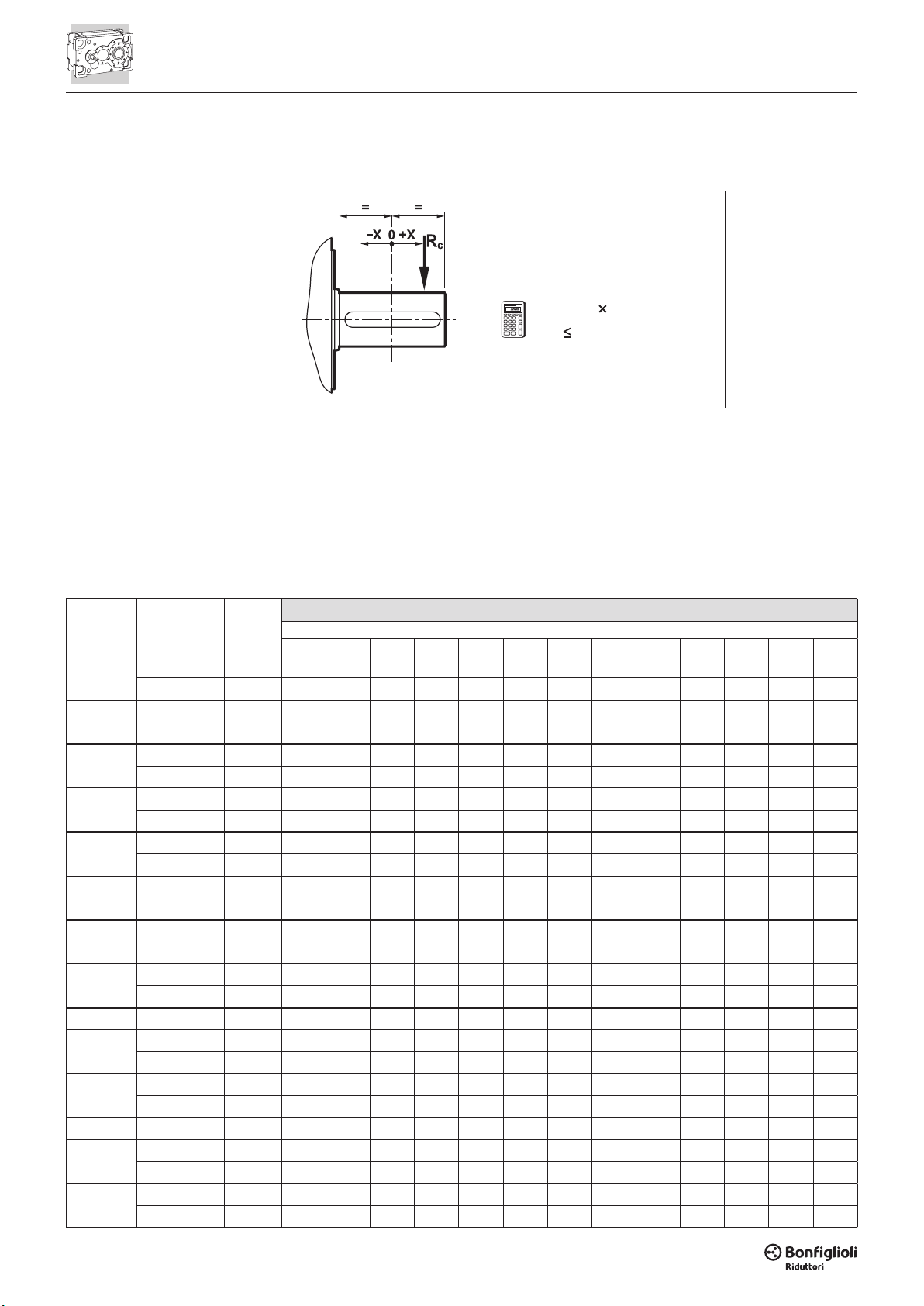
2.2.5 - VERIFICA SOPPORTAZIONE
RADIALE
2.2.5 - OVERHUNG LOADING
VERIFICATION
2.2.5 - PRÜFUNG DER
RADIALKRÄFTE
Rx=RnK
RcRx
I valori Rn1 max riportati in tabella sono
i carichi radiali massimi ammissibili; essi
possono subire delle limitazioni in funzio-
ne delle condizioni applicative.
Per un calcolo puntuale contattare il Ser-
vizio Tecnico Bonglioli.
The Rn1 max values listed in the table are
the maximum permissible overhung lo-
ads; these loads may have to be reduced
in certain applications.
For an exact value, please contact Bon-
glioli’s Technical Service.
Die in der Tabelle aufgeführten Höchst-
werte Rn1 max sind die maximal zulässi-
gen Radialkräfte; je nach Anwendungs-
bedingungen können sie Begrenzungen
unterworfen sein. Für eine spezische
Berechnung wenden Sie sich bitte an den
technischen Kundendienst von Bonglioli.

17
Rn2 max
K2
An2 max
[kN] x [mm] = [kN]
-100 -75 -50 -25 0 25 50 75 100 150 200 250 300 350 400 450 500
HDP 60 35.0 — — 1.20 1.09 1.00 0.74 0.58 0.48 0.41 0.32 — — — — — — — 17.5
HDP 70 40.0 — 1.34 1.20 1.09 1.00 0.77 0.63 0.53 0.46 0.36 0.30 — — — — — — 25.0
HDP 80 46.0 1.38 1.26 1.16 1.07 1.00 0.82 0.69 0.59 0.52 0.42 0.35 0.30 — — — — — 32.5
HDP 90 62.0 1.33 1.23 1.14 1.07 1.00 0.81 0.68 0.58 0.51 0.41 0.34 0.30 — — — — — 37.5
HDP 100 80.0 1.28 1.20 1.12 1.06 1.00 0.81 0.68 0.58 0.51 0.41 0.34 0.30 0.26 — — — — 40.0
HDP 110 86.0 1.27 1.19 1.12 1.06 1.00 0.83 0.71 0.63 0.56 0.45 0.38 0.33 0.29 0.26 0.24 — — 43.0
HDP 120 107.0 1.25 1.18 1.11 1.05 1.00 0.83 0.71 0.63 0.56 0.45 0.38 0.33 0.29 0.26 0.24 — — 53.5
HDP 130 160.0 1.20 1.14 1.09 1.04 1.00 0.86 0.75 0.67 0.60 0.50 0.43 0.38 0.33 0.30 0.27 0.25 — 80.0
HDP 140 190.0 1.20 1.14 1.09 1.04 1.00 0.86 0.75 0.67 0.60 0.50 0.43 0.38 0.33 0.30 0.27 0.25 — 95.0
HDP 150 200.0 1.15 1.11 1.07 1.03 1.00 0.92 0.85 0.80 0.75 0.66 0.60 0.54 0.49 0.45 0.41 0.38 0.35 100.0
HDP 160 220.0 1.15 1.11 1.07 1.03 1.00 0.92 0.85 0.80 0.75 0.66 0.60 0.54 0.49 0.45 0.41 0.38 0.35 110.0
i = Rn1 max K1
[kN] x [mm] =
-100 -75 -50 -25 0 25 50 75 100 150 200 250 300
HDP 120 2 7.9 … 25.4 17.8 — — 1.37 1.16 1.00 0.88 0.79 0.71 0.65 0.55 0.48 — —
HDP 120 3 25.8 … 56.1 6.3 — — 1.48 1.19 1.00 0.86 0.76 0.67 0.61 0.51 — — —
64.3 … 125.2 6.9 — — 1.54 1.21 1.00 0.85 0.74 0.65 0.59 0.49 — — —
HDP 120 4 128 … 277.2 2.1 — — — 1.18 1.00 0.87 0.76 0.68 0.62 — — — —
323.2 … 523.7 2.7 — — — 1.25 1.00 0.83 0.71 0.63 0.56 — — — —
HDP 130 2 7.3 … 12.3 28.0 — 1.47 1.27 1.12 1.00 0.90 0.82 0.76 0.69 0.54 0.45 0.38 —
14.1 … 21.7 22.1 — — 1.30 1.13 1.00 0.90 0.81 0.74 0.69 0.55 0.45 — —
HDP 130 3 21.8 … 48.1 11.9 — — 1.28 1.12 1.00 0.90 0.82 0.75 0.69 0.60 0.53 — —
56.5 … 108.3 8.1 — — 1.31 1.13 1.00 0.89 0.81 0.74 0.68 0.58 — — —
HDP 130 4 111.2 … 237.9 4.8 — — 1.33 1.14 1.00 0.89 0.80 0.73 0.67 0.57 — — —
274.5 … 534.5 1.8 — — — 1.15 1.00 0.88 0.79 0.72 0.65 — — — —
HDP 140 2 8.4 … 14.4 28.0 — 1.47 1.27 1.12 1.00 0.90 0.82 0.76 0.69 0.54 0.45 0.38 —
16.3 … 24.9 22.1 — — 1.30 1.13 1.00 0.90 0.81 0.74 0.69 0.55 0.45 — —
HDP 140 3 25.1 … 56.2 11.9 — — 1.28 1.12 1.00 0.90 0.82 0.75 0.69 0.60 0.53 — —
65.1 … 124.7 8.1 — — 1.31 1.13 1.00 0.89 0.81 0.74 0.68 0.58 — — —
HDP 140 4 141.6 … 277.5 4.8 — — 1.33 1.14 1.00 0.89 0.80 0.73 0.67 0.57 — — —
315.9 … 495.3 1.8 — — — 1.15 1.00 0.88 0.79 0.72 0.65 — — — —
HDP 150 2 7.9 … 14.1 31.7 1.60 1.39 1.23 1.10 1.00 0.91 0.84 0.78 0.73 0.61 0.51 0.44 0.38
15.4 … 19.6 26.4 — 1.43 1.25 1.11 1.00 0.91 0.83 0.77 0.71 0.58 0.48 0.40 —
HDP 150 3 21.5 … 38.1 26.6 — 1.44 1.26 1.11 1.00 0.91 0.83 0.77 0.71 0.57 0.47 0.40 —
43.5 … 77.0 17.4 — — 1.28 1.12 1.00 0.90 0.82 0.75 0.70 0.61 0.54 — —
HDP 150 4 89.0 … 157.8 10.8 — — 1.47 1.19 1.00 0.86 0.76 0.68 0.61 0.51 — — —
170.9 … 303.1 6.1 — — 1.45 1.18 1.00 0.87 0.76 0.68 0.62 0.52 — — —
HDP 160 2 9.0 …15.9 31.7 1.60 1.39 1.23 1.10 1.00 0.91 0.84 0.78 0.73 0.61 0.51 0.44 0.38
17.5 … 22.1 26.4 — 1.43 1.25 1.11 1.00 0.91 0.83 0.77 0.71 0.58 0.48 0.40 —
HDP 160 3 24.4 … 43.1 26.6 — 1.44 1.26 1.11 1.00 0.91 0.83 0.77 0.71 0.57 0.47 0.40 —
49.4 … 87.0 17.4 — — 1.28 1.12 1.00 0.90 0.82 0.75 0.70 0.61 0.54 — —
HDP 160 4 101.1 … 178.1 10.8 — — 1.47 1.19 1.00 0.86 0.76 0.68 0.61 0.51 — — —
194.1 … 342.2 6.1 — — 1.45 1.18 1.00 0.87 0.76 0.68 0.62 0.52 — — —
I valori dei carichi radiali ed assiali sono
quelli massimi ammissibili.
Per confrontare i valori di Rn2e An2 alle
diverse condizioni applicative vedere i ca-
pitoli 4.2 e 4.3.
The values for overhung and thrust loads
are the maximum permissible values.
To verify Rn2and An2values for different
applications, see sections 4.2 and 4.3.
Bei den angegebenen Radial- und Axial-
kräften handelt es sich um die maximal
zulässigen Werte. Zum Vergleich der Wer-
te von Rn2und An2unter den verschie-
denen Anwendungsbedingungen sind die
Kapitel 4.2 und 4.3 einzusehen.

18
2.2.6 - CARICHI AGENTI
SUGLI ALBERI
1. Carichi radiali albero lento
Riferirsi alla sezione 4.2 e vericare
che, per la congurazione di prodot-
to selezionata, e per le condizioni di
carico radiale e assiale applicate agli
alberi, le forze agenti esternamente
non superino quelle ammissibili per
il riduttore. Per carichi esterni parti-
colarmente gravosi, unicamente per i
gruppi HDP 60...HDP 90, sono dispo-
nibili cuscinetti con capacità di carico
maggiorata, specicabili mediante
l’opzione HDB. Se le forze esterne ec-
cedessero anche la capacità di carico
dei cuscinetti rinforzati, considerare l’i-
potesi di supportazione esterna degli
alberi, la riduzione dei carichi esterni
o, eventualmente, la selezione di un
riduttore di taglia superiore.
Per vericare la sopportazione ra-
diale riferirsi allo schema illustrato al
paragrafo 2.2.5 e confrontare la forza
radiale Rc gravante sull’albero con il
carico ammissibile Rx corrispondente
alla distanza di applicazione della for-
za stessa dalla mezzeria dell’albero.
Il carico ammissibile Rx2per l’albero
lento si ricava moltiplicando il valore
nominale Rn2, reperibile nelle tabelle
dati tecnici, per il coefciente di spo-
stamento K2.
I carichi radiali nominali Rn sono re-
lativi alle condizioni di calcolo più sfa-
vorevoli in quanto a verso di rotazione
e angolo di applicazione della forza,
e rappresentano pertanto un valore
conservativo. Per un calcolo puntuale
consultare il Servizio Tecnico di Bon-
glioli Riduttori. Congiuntamente al
carico radiale è applicabile un carico
assiale An2 ≤ 0.2 x Rn2.
2. Carichi assiali albero lento
Riferirsi alla sezione 4.3 e vericare
che, per la congurazione di prodot-
to selezionata, e per la combinazione
verso di rotazione albero / verso di ap-
plicazione della forza, il carico appli-
cato all’abero sia inferiore o uguale a
quello ammissibile riportato in tabella.
I valori di carico assiale ammissibile
riportati in tabella si riferiscono all’ap-
plicazione di forze puramente assiali.
In caso di congurazione S (albero
lento con calettatore), forze agenti
eccentricamente rispetto all’asse o in
presenza di componenti radiali, con-
sultare il Servizio Tecnico di Bonglioli
Riduttori.
2.2.6 - SHAFT LOADING
1.Overhung loads on output shaft
Refer to section 4.2, and verify that
both the radial and the axial force act-
ing onto output shaft do not exceed the
maximum permitted for the selected
product conguration.
Only for HDP units size 60 through
90 the HDB option provides higher
capacity bearings to cater for particu-
larly heavy external loads. If external
loads exceed the capacity of even the
heavy-duty bearings, consider pro-
viding external support for the drive
shafts, reducing external loads or, if
necessary, selecting a gear unit of the
next size up.
When checking the overhung load
capacity refer to scheme shown at
paragraph 2.2.5. Calculate the admis-
sible overhung load Rx that is relevant
to the distance the force applies from
shaft midpoint and compare this with
the force Rc that acts onto the shaft.
Multiply the nominal radial load Rn2,
as listed in the technical data section,
for the load location factor K2to get
the permissible overhung load Rx2for
the output shaft.
Rated overhung loads Rn are calcu-
lated for the most unfavourable condi-
tion as far as direction of rotation and
the angle the force applies onto the
shaft. Catalogue values are therefore
conservative, for an in-depth calcula-
tion contact the Technical Service of
Bonglioli Riduttori.
When a radial force applies a thrust
load An2 ≤ 0.2 x Rn2is also permitted.
2.Thrust loads on output shaft
Refer to section 4.3 and verify that
thrust force on the shaft does not ex-
ceed that specied in the chart for the
selected product conguration and
combination of direction of shaft rota-
tion / direction of force.
Permissible thrust loads refer exclu-
sively to forces applying axially on the
shaft.
Please contact Bonglioli Riduttori’s
Technical Service for information on
conguration S gearboxes (output
shaft with shrink disc) and for applica-
tions involving forces that act eccentri-
cally with respect to the shaft or invol-
ving overhung loads.
2.2.6 - WELLENBELASTUNG
1.Radialkräfte auf der Abtriebswelle
Auf den Abschnitt 4.2 Bezug nehmen
und sicherstellen, dass weder die au-
ßen einwirkenden Radial- noch die
Axialkräfte die für das Getriebe zu-
lässigen Kräfte übersteigen. Für be-
sonders schwere äußere Kräfte sind
– ausschließlich für die Gruppen HDP
60…HDP 90 – Lager mit erhöhter Be-
lastbarkeit verfügbar, die mit der Opti-
on HDB bestellt werden können. Falls
die äußeren Kräfte auch die Belastbar-
keit der verstärkten Lager übersteigen
sollten, muss eine externe Abstützung
der Wellen, die Reduzierung der äu-
ßeren Kräfte oder eventuell die Wahl
eines größeren Getriebes in Erwä-
gung gezogen werden.
Um die zulässige radiale Belastung zu
überprüfen, beziehen Sie sich auf das
in Abschnitt 2.2.5 dargestellte Sche-
ma. Berechnen Sie die zulässige Radi-
allast Rx in Abhängigkeit vom Abstand
zum Mittelpunkt der Welle und ver-
gleichen Sie diese mit der Radialkraft
Rc. Die zulässige Last Rx2 für die Ab-
triebswelle wird errechnet, indem der
Nennwert Rn2, der den Tabellen mit
den technischen Daten entnommen
werden kann, mit dem Verschiebungs-
koefzienten K2multipliziert wird.
Die Nenn-Radialkräfte Rn beziehen
sich auf die ungünstigsten Berech-
nungsbedingungen hinsichtlich Dreh-
richtung und Anwendungswinkel der
Kraft, und stellen daher einen konser-
vativen Wert dar. Für eine spezische
Berechnung wenden Sie sich bitte an
den technischen Kundendienst von
Bonglioli Riduttori. Zusammen mit
der Radialkraft ist eine Axialkraft von
An2 ≤ 0.2 x Rn2anwendbar.
2.Axialkräfte auf der Abtriebswelle
Auf den Abschnitt 4.3 Bezug nehmen
und prüfen, ob die auf die Welle ange-
wandte Last für die gewählte Produkt-
konguration und für die Kombination
Drehrichtung der Welle / Richtung der
Kraftanwendung kleiner oder gleich der
in der Tabelle angegebenen zulässigen
Last ist. Die in der Tabelle angegebe-
nen zulässigen Axialkraftwerte bezie-
hen sich auf reine Axialkräfte. Im Fall
der Konguration S (Abtriebswelle mit
Schrumpfverbindung) ist bei exzent-
risch zur Achse wirkenden Kräften oder
beim Vorhandensein radialer Kompo-
nenten der technische Kundendienst
von Bonglioli Riduttori zu kontaktieren.
Other manuals for HDP Series
2
This manual suits for next models
29
Table of contents
Other BONFIGLIOLI Industrial Equipment manuals


Popular Industrial Equipment manuals by other brands


Alien
Alien RAIN SILVER Series Setup instructions

Faster
Faster GLOVEFAST ASEPTIC Operating and maintenance manual

Siemens
Siemens SIRIUS S00 Original operating instructions

StorCase Technology
StorCase Technology Data Silo DS100 user guide

TriangleTube
TriangleTube PSRKIT25 manual

sirea
sirea AEA 5000 Installation and user manual