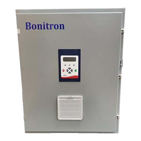
bonitron M3534R Series User manual

Legacy Model M3534R-RY
20A DC Bus Ride-Thru
for Variable Frequency AC Drives
Customer Reference Manual

Bonitron, Inc.
2
Bonitron, Inc.
Nashville, TN
An industry leader in providing solutions for AC drives.
ABOUT BONITRON
Bonitron designs and manufactures quality industrial electronics that improve the reliability of
processes and variable frequency drives worldwide. With products in numerous industries, and
an educated and experienced team of engineers, Bonitron has seen thousands of products
engineered since 1962 and welcomes custom applications.
With engineering, production, and testing all in the same facility, Bonitron is able to ensure its
products are of the utmost quality and ready to be applied to your application.
The Bonitron engineering team has the background and expertise necessary to design, develop,
and manufacture the quality industrial electronic systems demanded in today’s market. A strong
academic background supported by continuing education is complemented by many years of
hands-on field experience. A clear advantage Bonitron has over many competitors is combined
on-site engineering labs and manufacturing facilities, which allows the engineering team to have
immediate access to testing and manufacturing. This not only saves time during prototype
development, but also is essential to providing only the highest quality products.
The sales and marketing teams work closely with engineering to provide up-to-date information
and provide remarkable customer support to make sure you receive the best solution for your
application. Thanks to this combination of quality products and superior customer support,
Bonitron has products installed in critical applications worldwide.

Bonitron, Inc.
3
AC DRIVE OPTIONS
In 1975, Bonitron began working with AC inverter drive specialists at synthetic fiber plants to
develop speed control systems that could be interfaced with their plant process computers. Ever
since, Bonitron has developed AC drive options that solve application issues associated with
modern AC variable frequency drives and aid in reducing drive faults. Below is a sampling of
Bonitron’s current product offering.
WORLD CLASS PRODUCTS
Undervoltage Solutions
Overvoltage Solutions
Uninterruptible Power for Drives
(DC Bus Ride-Thru)
Voltage Regulators
Chargers and Dischargers
Energy Storage
Braking Transistors
Braking Resistors
Transistor/Resistor Combo
Line Regeneration
Dynamic Braking for Servo Drives
Common Bus Solutions
Portable Maintenance Solutions
Single Phase Power Supplies
3-Phase Power Supplies
Common Bus Diodes
Capacitor Formers
Capacitor Testers
Power Quality Solutions
Green Solutions
12 and 18 Pulse Kits
Line Regeneration

M3534R 20A
4
1. INTRODUCTION.......................................................................................................................7
1.1. Who Should Use........................................................................................................................7
1.2. Purpose and Scope.....................................................................................................................7
1.3. Manual Version and Change Record.........................................................................................7
Figure 1-1: M3534R 20A in A5 Chassis ..............................................................................................7
1.4. Symbol Conventions Used in this Manual and on Equipment..................................................8
2. PRODUCT DESCRIPTION.........................................................................................................9
2.1. Related Products........................................................................................................................9
2.2. Part Number Breakdown.........................................................................................................10
Figure 2-1: Example of Part Number Breakdown..............................................................................10
Table 2-1: System Voltage Rating Codes...........................................................................................10
2.3. General Specifications.............................................................................................................11
Table 2-2: General Specifications Chart.............................................................................................11
2.4. General Precautions and Safety Warnings ..............................................................................12
3. INSTALLATION INSTRUCTIONS.............................................................................................13
3.1. Product Inspection...................................................................................................................13
3.2. Site Selection...........................................................................................................................13
3.3. Mounting.................................................................................................................................13
3.4. Wiring and Customer Connections .........................................................................................14
Table 3-1: 20 Amp Power Field Wiring Connections ........................................................................14
3.4.1. Power Wiring - RTM To Drive Interconnections .........................................................................14
3.4.2. Control Interface Wiring...............................................................................................................15
Figure 3-1: A5 Chassis Field Connection Terminal Layout...............................................................16
Figure 3-2: A5 Internal Layout with I3 Interface ...............................................................................16
3.5. Typical Configurations............................................................................................................17
Figure 3-3: Typical 20 Amp M3534R Interconnection with Existing Drive System.........................17
4. OPERATION...........................................................................................................................19
4.1. Functional Description............................................................................................................19
Figure 4-1: Basic 20A M3534R RTM Internal Power Flow Circuit Diagram ...................................19
4.2. Features ...................................................................................................................................20
4.2.1. Signal I/O ......................................................................................................................................20
Table 4-1: Control Signal Details- 3534R2 Control Board for Standard Models...............................21
Table 4-2: Control Board Control Signal Details for Modules with DP10 “I3” Option.....................21
Table 4-3: Status Signal Component Details- 3534R2 Control Board for Standard Models..............21
Table 4-4: Status Signal Component Details for Modules with DP10 “I3” Option ...........................21
Table 4-5: Control Status Signal Component Specifications .............................................................22
Table 4-6: Fault / Status Contact Logic Details –3534R2 Board ......................................................22
4.2.2. Indicators.......................................................................................................................................22
Figure 4-2: ASB 3534R2 RTM Control Board Features....................................................................22
Figure 4-3: ASB 3534I3 Interface Board Features.............................................................................23
4.2.3. Remote or Cabinet Door System Status Display and Test Module...............................................24
4.3. Startup .....................................................................................................................................25
4.3.1. Pre-Power Checks.........................................................................................................................25
4.3.2. Startup Procedure And Checks......................................................................................................25
4.4. Operational Adjustments.........................................................................................................26
4.4.1. Threshold Voltage Adjustment Procedure For Model M3534 Ride-Thru Modules......................26
Table 4-7: Factory Setpoints for Threshold and Test Boost Voltages................................................27
4.4.2. Determining Threshold Voltage Setpoint......................................................................................27

Table of Contents
5
4.4.3. Adjustment Pots ............................................................................................................................28
5. MAINTENANCE AND TROUBLESHOOTING............................................................................29
5.1. Periodic Testing.......................................................................................................................29
5.1.1. Periodic Maintenance Procedures for M3534R Module Without Optional Display Panel ...........29
5.1.2. Periodic Maintenance Procedures for M3534R Module With Optional DP10 Display Panel ......30
5.2. Maintenance Items ..................................................................................................................31
5.2.1. Capacitor Replacement Recommendations...................................................................................31
5.3. Troubleshooting.......................................................................................................................32
Table 5-1: Detailed Troubleshooting Guide.......................................................................................32
6. ENGINEERING DATA.............................................................................................................33
6.1. Ratings Charts ......................................................................................................................... 33
Table 6-1: Model M3534R Ride-Thru Module Ratings.....................................................................33
Table 6-2: Model M3534R Ride-Thru Module Voltage Levels.........................................................33
Table 6-3: De-Rating Table................................................................................................................33
6.2. Watt Loss.................................................................................................................................34
6.3. Fuse/Circuit Breaker Sizing and Rating..................................................................................34
6.3.1. Recommended Input Power Wiring Sizes And Power Source Fusing..........................................34
Table 6-4: Input Power Wiring Sizes and Fusing...............................................................................34
6.4. Dimensions and Mechanical Drawings...................................................................................35
Figure 6-1: M3534R Control Module A5 Chassis Dimensional Outline ...........................................35
6.5. Supplemental Drawings ..........................................................................................................36
6.5.1. Schematics ....................................................................................................................................36
Figure 6-2: 3534R2 TB5 Status Signal...............................................................................................36
Figure 6-3: 3534I3 Control and Status Signal ....................................................................................36
7. APPENDICES..........................................................................................................................37
7.1. Drive Ride-Thru Selection Guide............................................................................................37
7.2. Installation Considerations for Drive Ride-Thru Systems ......................................................37
7.3. Application Notes for M3534R modules ................................................................................38
7.4. Specifying an Ultracapacitor Storage Bank for full outage protection with the M3534R ...... 38
7.4.1. Energy Required for Outage..........................................................................................................39
7.4.2. Minimum Capacitor Bank Voltage ...............................................................................................39
7.4.3. Peak Current..................................................................................................................................40
7.4.4. Capacitor Specifications................................................................................................................40
7.4.5. Minimum Series String .................................................................................................................40
7.4.6. Available Joules ............................................................................................................................41
7.5. Diode Sharing with a Bonitron Ride-Thru..............................................................................42
Figure 7-1: Diode Sharing Example...................................................................................................43

M3534R 20A
6
This page intentionally left blank

User’s Manual
7
1. INTRODUCTION
1.1. WHO SHOULD USE
This manual is intended for use by anyone who is responsible for integrating, installing,
maintaining, troubleshooting, or using this equipment with any AC drive system.
Please keep this manual for future reference.
1.2. PURPOSE AND SCOPE
This manual is a user’s guide for the 20 Amp Model M3534R 2-Second, 50% DC Bus
Sag Ride-Thru module that were produced through 2009. It will provide the user with
the necessary information to successfully install, integrate, and use the M3534R
module in a variable frequency AC drive system.
In the event of any conflict between this document and any publication and/or
documentation related to the AC drive system, the latter shall have precedence.
1.3. MANUAL VERSION AND CHANGE RECORD
DP10 details were clarified in Rev 02a of this 20A (12kW) manual.
Rev 02b has minor format changes.
Rev 02c has wiring and format changes.
Rev 03a contains updates for the M3534-RY legacy version.
Figure 1-1: M3534R 20A in A5 Chassis

M3534R 20A
8
1.4. SYMBOL CONVENTIONS USED IN THIS MANUAL AND ON EQUIPMENT
Earth Ground or Protective Earth
AC Voltage
DC Voltage
DANGER!
Electrical Hazard - Identifies a statement that indicates a shock
or electrocution hazard that must be avoided.
DANGER!
DANGER: Identifies information about practices or
circumstances that can lead to personal injury or death,
property damage, or economic loss.
CAUTION!
CAUTION: Identifies information about practices or
circumstances that can lead to property damage, or economic
loss. Attentions help you identify a potential hazard, avoid a
hazard, and recognize the consequences.
CAUTION!
Heat or burn hazard - Identifies a statement regarding heat
production or a burn hazard that should be avoided.

User’s Manual
9
2. PRODUCT DESCRIPTION
Variable Frequency Drives (VFDs) are commonly used in industry to improve control over
continuous process applications, such as in the textile and semiconductor industries, where
very accurate motor speed control is required. Unfortunately, these systems are quite
susceptible to problems caused by fluctuations of incoming power, such as AC line voltage
sags or outages. Long downtimes as well as large and costly production losses have been
experienced due to VFD shutdowns caused by these occurrences.
Bonitron’s Model M3534 series of DC Bus Ride-Thru Modules (RTM) provide protection
from AC line voltage sags and outages for AC drive systems that use a fixed DC bus as
with AC PWM VFDs by temporarily storing energy internally and releasing it back into the
DC bus when needed. This allows the drive to “ride through” these events, maintaining
motor speed and torque, without experiencing drive shutdown.
The majority of AC line voltage fluctuations that occur in three-phase distribution systems
have a magnitude (decrease from nominal voltage) of less than 50% and duration of less
than 2 seconds. The Model M3534R DC Bus Ride-Thru Control module provides sufficient
ride through capability to handle these types of voltage sags.
2.1. RELATED PRODUCTS
S3534UR AND S3534BR SERIES RIDE-THRU MODULES
Adding ultracapacitor (UR) or battery (BR) energy storage allows M3534R modules to
maintain loads under 100% outage conditions.
M3460 SERIES RIDE-THRU MODULES
The M3460R 230-480VAC Ride-Thru Module is designed to maintain inverter bus
under 3-phase 50% sag conditions with multiple cabinet systems rated up to 1200kW.
The M3460B 350-540VDC Ride-Thru Module is designed to boost a battery bank up to
inverter level under 100% outage conditions.
M3528 ULTRA CAP /BATTERY CHARGER
M3528 is a voltage and current limited power supply used to charge electrical energy
storage devices such as battery banks or ultracapacitor reservoirs for industrial voltage
levels of 208 - 480VAC. User inputs allow for remote enable and second setpoint
charging for battery equalization.
M3628 ULTRA CAP DISCHARGE CONTROLLER AND BATTERY BANK TESTER
M3628 Modules deplete hazardous stored energy in Ultracapacitor Ride-Thru Systems.
Standard packages are typically sized to discharge the voltage to 50V in 1 minute.

M3534R 20A
10
2.2. Part Number Breakdown
Figure 2-1: Example of Part Number Breakdown
BASE MODEL NUMBER
The Base Model Number for all M3534 Series 2 second, 50% sag, DC Bus Ride-Thru
Modules (RTM) is M3534R.
SYSTEM VOLTAGE RATING
The System Voltage Rating indicatesthe nominal AC/DC voltage levels of the AC Drive
system the RTM is intended to support. Units are available for several standard AC/DC
voltages. The System Voltage is indicated by a code letter.
Table 2-1: System Voltage Rating Codes
RATING
CODE
VOLTAGES
(NOMINAL AC LINE /DC BUS)
L
230VAC Line / 320VDC
E
400VAC Line / 565VDC
H
460VAC Line / 640VDC
POWER RATING (KW)
The Power Rating indicates the maximum power in kilowatts that can safely be handled
by the M3534R RTM during outage durations of 2 seconds. This rating is directly
represented by a 3-digit value based on the nominal DC system voltage rating and the
maximum output current rating of the RTM. For instance, the rating code for a 12kW
RTM is 012.
CHASSIS STYLE
The 20 amp Model M3534R RTM comes in the A5 Type-1 panel-mountable enclosure.
Refer to Section 6.4 for chassis dimensions.
DISPLAY OPTIONS
The 20 amp Model M3534R RTM is available with a DP10 display option. This includes
several status indicator LEDs, a Ride-Thru Active counter and a push-button to initiate
the ‘test” feature.
M3534R
H
012
DP10
BASE MODEL NUMBER
SYSTEM VOLTAGE RATING
POWER RATING (KW)
CHASSIS STYLE
DISPLAY OPTIONS
A5

User’s Manual
11
2.3. GENERAL SPECIFICATIONS
Table 2-2: General Specifications Chart
PARAMETER
SPECIFICATION
AC Input Voltage
208 - 480VAC
DC Output Voltage
265 - 585VDC minimum
295 - 650VDC nominal
Max. DC Output Current
20A
Maximum Kilowatt Rating
12kW
Maximum Sag Duration
2 seconds
Duty Cycle Rating
1% duty rated at 50% voltage with 100% load
Pre-charge Time
Less than 100 milliseconds
Inactive Power Usage
Less than 15W
Fault / Status Indicators
Power (PWR)
Overtemp (OT)
Ride-Thru Active (RTA)
Power Connections
3-Phase AC Line Input, Ground
DC Bus Output
External Energy Reservoir or Bus Support Module
Control Inputs
24V input initiates TEST cycle
24V input disables BOOST mode
Status Outputs
OT relay contacts available on all models
RTA relay contacts available on all models
Operating Temp.
40°C
Storage Temp
-20°C to +65°C
Humidity
Below 90% non-condensing
Atmosphere
Free of corrosive gas and conductive dust

M3534R 20A
12
2.4. GENERAL PRECAUTIONS AND SAFETY WARNINGS
DANGER!
HIGH VOLTAGES MAY BE PRESENT!
NEVER ATTEMPT TO OPER ATE THIS PRODUCT WIT H THE
ENCLOSURE COVER REMO VED!
NEVER ATTEM PT TO SE RVICE THIS PRODUCT WIT HOUT
FIRST DISCONNECTING POWER TO AND FROM THE UNIT !
ALWAYS ALLOW ADEQUATE TIME FOR RESIDUAL VOLTAGES
TO DRAI N BEFORE REMOVING THE ENCLOSURE C OVER.
FAILURE TO HEED THESE WARNINGS MAY RESULT
IN SERIOUS BODILY INJURY OR DEATH!
CAUTION!
THIS PRODUCT WILL GENERATE HIGH AMBIENT
TEMPERATURES DURING OPERATION.
THIS PRODUCT SHOULD BE INSTALLED ACCORDIN GLY ON
NON-FLAMMABLE SURFACES W ITH CLEARANCES OF AT
LEAST TWO INCHES IN ALL DIRECTIONS.
ALWAYS ALLOW AM PLE TI ME FOR THE UNIT TO COOL
BEFORE ATTEMPTI NG SE RVICE ON THIS PRODUCT.
BEFORE ATT EMPTING INS T ALLATION OR REM OVAL OF THIS
PRODUCT,BE SURE TO REVIEW ALL DRIVE AND/OR
RESISTIVE LOAD DOCUM ENTATION FOR PERTINENT SAFETY
PRECAUTIONS.
INSTALLATION AND/OR REMOVAL OF THI S P RODUCT
SHOUL D ONLY BE ACCOMPLISHED BY A QUAL IFI ED
ELECTRICIAN IN ACCOR DANCE WITH NATIONAL
ELECTRICAL CODE OR EQUIVALENT RE GULATIONS.
ANY QUESTIONS AS TO APPLICATION, INSTALLATION, OR SERVICE
SAFETY SHOULD BE DIRECTED TO THE EQUIPMENT SUPPLIER.

User’s Manual
13
3. INSTALLATION INSTRUCTIONS
DANGER!
Installation and/or removal of this product should only be performed by a
qualified electrician in accordance with National Electrical Code or local
codes and regulations.
Proper installation of the Model M3534R Ride-Thru Module should be accomplished
following the steps outlined below.
Be sure to refer to the AC Drive instruction manual as these steps are performed.
Please direct all installation inquiries that may arise during the installation and start up of
this braking product to the equipment supplier or system integrator.
See Installation Considerations in Section 7.2 of this manual for additional information.
3.1. PRODUCT INSPECTION
Upon receipt of this product, please verify that the product received matches the
product that was ordered and that there is no obvious physical damage to the unit. If
the wrong product was received or the product is damaged in any way, please contact
the supplier from which the product was purchased.
3.2. SITE SELECTION
The installation site for the module should be chosen with several considerations in
mind:
The unit has a Type-1 rating and will therefore require some protection from the
elements.
Conduit access for field power wiring is provided through the bottom surface of the
enclosure, and for control / status through the top.
The unit will require a minimum clearance of two (2) inches above and below it to
allow for proper airflow for cooling. Avoid mounting the Ride-Thru Module with its
bottom air intake near heat sources.
The mounting surface should be clean and dry.
3.3. MOUNTING
Once the installation site has been selected as outlined above, the unit should be
mounted in place. The RTM enclosure is provided with mounting slots andslotted holes
to be mounted on ¼” diameter studs or bolts. Required mounting hardware is not
supplied with the RTM.
Mounting holes should be drilled and mounting studs or anchors installed before
positioning the enclosure. Once the studs or bolts are in place the RTM can be hung
in position. Be sure all mounting hardware is tightened securely.
To determine the correct mounting dimensions and provisions for the unit being
mounted, refer to the Dimensional Outline in Section 6.4 of this manual.

M3534R 20A
14
3.4. WIRING AND CUSTOMER CONNECTIONS
This section provides information pertaining to the field wiring connections of the
M3534R Ride-Thru Module. Actual connection points and terminal numbers of the AC
Drive system will be found in the documentation provided with that system.
Be sure to review all pertinent AC Drive System documentation as well as the RTM to
Drive Interconnection details listed below before proceeding.
DANGER!
Interconnect wiring of this product should only be done by a qualified electrician
in accordance with National Electrical Code or local codes and regulations.
Table 3-1: 20 Amp Power Field Wiring Connections
TERMINAL
TYPE
FUNCTION
WIRING
SPECIFICATIONS
MIN
WIRE
AWG
MAX
WIRE
AWG
TORQUE
LB-IN
L1 L2 L3
AC Input
600VAC
14
10
20 lb-in
BSM
+ ─
DC Input
600VAC
22
8
20 lb-in
DC Bus
+ ─
DC Output
600VAC
14
10
20 lb-in
GND
Ground
600VAC
18
10
20 lb-in
3.4.1. POWER WIRING -RTM TO DRIVE INTERCONNECTIONS
Illustrations and a table are provided to assist with the field connection of the
M3534R Ride-Thru Module to an existing AC drive system. Also, be sure to
refer to the documentation supplied with the drive system for field connection
points within that system. The DC bus should always be connected directly to
the drive output capacitor bank. Connecting upstream of theDC bus inductors
may cause damage to the drive and Ride-Thru module.
Typical Field Connection terminal layouts for the M3534R RTM are shown in
Figures 3-1 and 3-2. Figure 3-3 shows a typical power interconnection of the
M3534R Ride-Thru Module with an existing AC drive system.
Field connection terminals for the Ground, AC Line Input, External Energy
Reservoir, and DC Bus are located near the bottom of the RTM enclosure and
can be accessed by removing the cover panel from the enclosure.
3-PHASE AC LINE INPUT (L1, L2, L3)
The 3-phase AC Line input connections are made directly to the fuse block at
L1, L2, and L3. Connections can be made using 10 AWG wire. These screw
terminals will accept #10 ring or fork lugs. Torque all terminal screws to 20 lb-
in maximum.
DC BUS OUTPUT (DC BUS +─)
The DC Bus Output connections are made directly to the fuse block at DC+ ─.
Connections can be made using 10 AWG wire. These screw terminals will
accept #10 ring or fork lugs. Torque all terminal screws to 20 lb-in minimum.
EXTERNAL ENERGY STORAGE CONNECTIONS (BSM +─)
For all units in the A5-chassis type, make the DC input connections from the
external storage bank to the connector located just above the DC Output

User’s Manual
15
fuses. (See Figure 3-1.)Connections can be made using 10 AWG wire.
Torque terminal screws to 20 lb-in maximum.
GROUND
Earth ground stud is provided on the chassis for all models.
Make the Ground interconnection to Ground stud located on the lower left
inner wall of the RTM enclosure. Connection to the Ground terminal can be
made using 10 AWG wire. Terminal will accept a #10 ring or fork lug
termination. Torque nut on ground stud to 20 lb-in maximum.
3.4.1.1. SOURCE CONSIDERATIONS
Input feed must be capable of delivering 2x rated current for 2 seconds at
50% sag levels. Feeds sized to account for 150 - 200% inverter starting
torque are adequate.
NOTE: Drive and Ride-Thru will not pull power at the same time.
3.4.2. CONTROL INTERFACE WIRING
3.4.2.1. TEST INPUT CONNECTIONS
Test input connections may be made across TB3-5 (+) and TB3-6 (-) of
the ASB 3534R2 Control Board. Torque terminal screws to 2 lb-in max.
See Figures 3-2 and 4-2.
3.4.2.2. DISABLE INPUT CONNECTIONS
Disable input connections may be made across TB4-1 (Positive) and TB4-
2(Negative) of the ASB 3534R2 Control Board. Torque terminal screws
to 2 lb-in max. See Figures 3-2 and 4-2.
For units utilizing the DP10 Option, connect at I3 TB4-6 (+) and 5 (-). See
Figure 4-3.
3.4.2.3. FAULT /STATUS MONITORING CONNECTIONS FOR STANDARD
MODELS
On the ASB 3534R2 Control Board:
OVERTEMP (OT) Relay: TB4-5-5 (OT) and TB5-3 (Common). See
Figures 3-2 and 4-2.
Ride-Thru Active (RTA) Relay: TB5-4 (RTA) and TB5-3 (Common).
Torque all connections to 2 lb-in max.
See Figures 3-2 and 4-2.
3.4.2.4. FAULT /STATUS MONITORING CONNECTIONS FOR MODELS WITH
DP10 (3534I3 BOARD)
On the ASB 3534I3 Interface Board:
Ride-Thru Active (RTA) Relay: TB4-1 (J2 post) and TB4-2 (common).
See Figures 4-3, 6-2 and 6-3.
Over-Temp (OT) Relay: TB4-3 (J1 post) and TB4-4 (common). See
Figure 4-3.
Torque all connections to 2 lb-in max.

M3534R 20A
16
Figure 3-1: A5 Chassis Field Connection Terminal Layout
Figure 3-2: A5 Internal Layout with I3 Interface
Dwg: 120211 and 120213 Rev: 20120621

User’s Manual
17
3.5. TYPICAL CONFIGURATIONS
Figure 3-3: Typical 20 Amp M3534R Interconnection with Existing Drive System
Dwg: 080455 Rev: 20100903

M3534R 20A
18
This page intentionally left blank

User’s Manual
19
4. OPERATION
4.1. FUNCTIONAL DESCRIPTION
The M3534R series of Ride-Thru Modules (RTMs) employs IGBT switching technology
to regulate the inverter DC bus to a preset minimum voltage level. As the incoming AC
voltage level drops, the RTM “activates”, boosting a rectified DC voltage up to the
minimum DC bus voltage level specified for the inverter, allowing it to “ride through” the
sag or outage event.
Upon application of power to the M3534R, its DCbus will begin to prechargevia internal
NTC surge limiters. When the bus reaches 150VDC, the internal logic power supply of
the RTM will begin switching, and will supply the +24V and ±15V DC needed to power
the control circuitry. At this point the PWR LED will illuminate. In addition, the RTA
relay within the RTM and its corresponding RTA LED may turn on briefly during the
RTM’s precharge period. Once the RTM’s DC bus has fully precharged to its preset
nominal value (see Ratings chart in Section 6 for voltage levels), the control module’s
PWR LED will be ON, and the RTA and OVERTEMP LEDs will be OFF.
During a voltage sag or outage,the inverter DC bus level willdecrease, pulling the RTM
bus down with it. Once the DC bus drops below a preset lowlimit (“threshold”) the RTM
will become “active”. When this occurs, the RT ACTIVE front panel LED will illuminate,
the internal RTA relay contact will change states, the cooling fan will begin running in
order to cool the internal IGBT heatsink, and the DC bus level will be supported by the
RTM. The RT ACTIVE LED and internal relay will be ON only while the RTM is active
(real time). The cooling fan will continue running for 2 minutes after activity stops.
If the RTM begins supplying power continuously, possibly due to a low line level,
incorrect threshold adjustment, or inverter fuse failure, an over temperature condition
may occur. If this happens, the OVERTEMP front panel LED will turn ON and the
internal OT relay will energize, shutting down the switching circuits and allowing the DC
bus to drop to the nominal level. At this point, the RTM will continue supplying power,
via an internal bridge rectifier, at the nominal line level.
If the sag duration exceeds 50% while the RTM is fully loaded, the output DC bus level
will begin to drop. If the inverter’s LOW BUS trip level is reached, the inverter will shut
down. When the DC bus drops to 100V, the RTM’s internal logic supply will shut down.
Figure 4-1: Basic 20A M3534R RTM Internal Power Flow Circuit Diagram
Dwg: 060156 Rev: 20110627

M3534R 20A
20
4.2. FEATURES
4.2.1. SIGNAL I/O
4.2.1.1. CONTROL INPUTS
FOR STANDARD MODELS
The DISABLE command is connected to TB4 1&2 of the 3534R2
control board. 24V will inhibit the module from boosting. No
connection allows normal operation. Use this to prevent excessive
battery cycling while system power is normal.
The TEST command is connected to TB3 5&6 on the 3534R2 control
board. 24V initiates TEST. Input is isolated from drive common.
FOR MODELS WITH DP10 OPTION (I3 BOARD)
The DISABLE is connected to the 3534I3 interface board at TB4-6&5.
4.2.1.2. RTM FAULT LOGIC DETAIL OVERVIEW
All standard M3534R Ride-Thru Control Modules are equipped with basic
Fault / Status outputs. These outputs are accessible via on-board terminal
strip TB5 for 20 amp models. Each output is jumper selectable to provide
for either “Normally Open” or “Normally Closed” dry contact output. Each
contact is in its “Normal” condition while its controlling relay is “Inactive” or
at rest.
All units are shipped with all Fault / Status outputs in the “Normally Open”
position.
Refer to the ASB 3534R2 Control Board layout drawing in Figure 4-2 for
the locations of each of the components listed in Tables 4-1 thru 4-6.
4.2.1.3. ASB 3534R2 STATUS OUTPUT CONFIGURATION JUMPERS
FOR MODELS WITH DP10 OPTION (I3 BOARD)
Fault Signals are available on the 3534I3 board.
FOR STANDARD MODELS
The purpose and setting for each of the configuration jumpers provided
on the ASB 3534R2 RTM Control board is described below. Please refer
to Figure 4-2 for the locations of each of the jumpers listed below. (See
Figures 6-2 and 6-3 for additional details.)
Each output is jumper selectable to provide “Normally Open” (NO) or
“Normally Closed” (NC) dry contact outputs. Each contact is in its
“Normal” condition while its controlling relay is “Inactive” or at rest. Leaving
a jumper OFF will disable the fault output.
Each Fault / Status Output has a corresponding LED indicator. When a
Fault / Status LED is ON, its corresponding relay can be assumed to be
“Active”.
JUMPER J1 –OVER-TEMP FAULT OUTPUT:
This jumper allows the user to select the output contact state of Over-
Temp fault relay K2. K2 is pulled in when power is applied and there is
no overtemp condition. This jumper must be set to “Normally Closed”
(NC) for cabinet systems.
This manual suits for next models
2
Table of contents
Other bonitron Controllers manuals
Popular Controllers manuals by other brands
YEYIAN
YEYIAN TYPHOON LII user manual
bluelab
bluelab Dosetronic instruction manual
Hanna Instruments
Hanna Instruments HI 720 instruction manual
AMX
AMX NetLinx NI-3101-SIG Operation/reference guide
Light Rider
Light Rider LR512 Technical data sheet
Dometic
Dometic MPC01 Plus Installation and operating manual
