Bonnet OPTIMUM 700 User manual

OPTIMUM 700 & 900
ELECTRIC
PASTA COOKERS
BUILDER’S SPECIFICATIONS
Part A: Technical characteristics
Part B: Technical instructions for the installer
- WARNING -
•
Installation and repairs must be carried out by personnel approved by the manufacturer and in
accordance with current regulations and standards.
•
If any modifications are made the manufacturer can accept no responsibility whatsoever.
•
These appliances must be used in a well-ventilated area.
•
Read the notice carefully before installation.
•
When handling it, it is imperative to leave the appliance on its base till final installation.
3BE390723NI

Page 1 3BE390723NI – 11/09
BONNET GRANDE CUISINE
Registered Office:
Rue des Frères Lumière - Z.I Mitry Compans
77292 MITRY MORY Cedex
TABLE OF CONTENTS
ELECTRIC
PASTA COOKERS
A) TECHNICAL CHARACTERISTICS …....................................................... 2
B) TECHNICAL INSTRUCTIONS FOR THE INSTALLER
1. FIRM PLATES ………………........................................…....................................................... 4
1.1 PLATE ……..………..……….……...….…………...….….……………………………………….……..
4
1.2 LOCATION OF THE PLATE ……….………………………….……..……………………………..….. 4
2. INSTALLATION: GENERALITIES ..………….…………………………………..………………… 5
2.1 GENERAL REQUIREMENTS …………..……….……...….….….………………………………….. 5
2.2 HANDLING ……….....…………….…………………………..……………………………………….. 5
2.3 UNPACKING ………...….………..………………..…………...……………………………………… 5
2.4 ACCESS TO THE COMPONENTS PLACED BEHIND THE FASCIA ……..………….…………. 6
3. INSTALLATION: PUTTING IN PLACE ……………………………………….….….…………….. 7
3.1 ASSEMBLY OF CANTILEVER APPLIANCES TO A WALL ……….……………………………… 7
3.2 ASSEMBLY OF APPLIANCES TO AN INDIVIDUAL BASE ………..………………..………………
9
3.3 ASSEMBLY OF APPLIANCES ON A COMMON BASE ……………………………..………………
10
3.4 ASSEMBLY OF APPLIANCES ON A MASONRY BASE ……………………..……………..……… 11
4. INSTALLATION: CONNECTIONS ……………………………………………...….………………. 13
4.1 ELECTRIC CONNECTION ……….……………..…...……...………..…….…………………………..
13
4.2 WATER CONNECTION .………...……...……………………..…..……………………………….…...
14
4.3 DRAINAGE CONNECTION ….……….……………………………..……………………………….....
14

Page 2 3BE390723NI – 11/09
BONNET GRANDE CUISINE
Registered Office:
Rue des Frères Lumière - Z.I Mitry Compans
77292 MITRY MORY Cedex
A: TECHNICAL CHARACTERISTICS
OPTIMUM 700, Electric pasta cooker
P075755
MODEL B-B709.CP400
DIMENSIONS (mm)
Width 400
Depth x Height 730 x 959
Basket 90 x 280 x 160
CAPACITIES (mm)
Tank (litres) 20
Basket (kg) 0.5
PACKAGING (mm)
Width 500
Depth x Height 830 x 1150
WEIGHT (KG) 70
ELECTRICITY (Three-phase 230V+T or 400V+N+T)
Power (kW) 230V 3a.c. 9
400V 3Na.c. 9
Max. intensity (A) 230V 3a.c. 22.6
400V 3Na.c. 13
HOT WATER
Pressure 2.5/6 bars
Water hardness 70 ppm
Max. temperature 60°C
Connection Hose ∅20/27 (3/4″)
DRAINAGE
Connection Diameter 28
SAFETY OPERATION Heating with no water
TYPE OF APPLIANCE Back to the wall or another appliance
ELECTRIC CONNECTION
Electric outlet at 390 mm above the floor.
This document is not contractual; Edition 11/2009 – 3BE0584FT
ELECTRIC connection
(Foresee a cable with 1.5 m free length)
HOT WATER
DRAINAGE

Page 3 3BE390723NI – 11/09
BONNET GRANDE CUISINE
Registered Office:
Rue des Frères Lumière - Z.I Mitry Compans
77292 MITRY MORY Cedex
OPTIMUM 900, Electric pasta cooker
P075756
MODEL B-B909.CP400
DIMENSIONS (mm)
Width 400
Depth x Height 920 x 959
Basket 90 x 280 x 160
CAPACITIES (mm)
Tank (litres) 20
Basket (kg) 0.5
PACKAGING (mm)
Width 500
Depth x Height 1030 x 1150
WEIGHT (KG) 55
ELECTRICITY (Three-phase 230V+T or 400V+N+T)
Power (kW) 230V 3a.c. 9
400V 3Na.c. 9
Max. intensity (A) 230V 3a.c. 22.6
400V 3Na.c. 13
HOT WATER
Pressure 2.5/6 bars
Water hardness 70ppm
Max. temperature 60°C
Connection Hose ∅20/27 (3/4″)
DRAINAGE
Connection Diameter 28
SAFETY FUNCTIONING Heating without water
TYPE OF APPLIANCE Back to the wall or another appliance
ELECTRIC CONNECTION
Electric outlet at 390 mm above the floor.
This document is not contractual; Edition 11/2009 – 3BE0585FT
ELECTRIC connection
(Foresee a cable with 1.5 m free length)
HOT WATER
DRAINAGE

Page 4 3BE390723NI – 11/09
BONNET GRANDE CUISINE
Registered Office:
Rue des Frères Lumière - Z.I Mitry Compans
77292 MITRY MORY Cedex
1. FIRM PLATE
1.1 PLATE
In any correspondence about your equipment, please indicate:
- The model number (Model.)
- The serial number (Fab.Nr.)
- The date (Date).
Firm plate
1.2 LOCATION OF THE FIRM PLATE
The firm plates are fixed on the control board (see the diagrams hereafter).
Location of the firm plate

Page 5 3BE390723NI – 11/09
BONNET GRANDE CUISINE
Registered Office:
Rue des Frères Lumière - Z.I Mitry Compans
77292 MITRY MORY Cedex
2. INSTALLATION: GENERALITIES
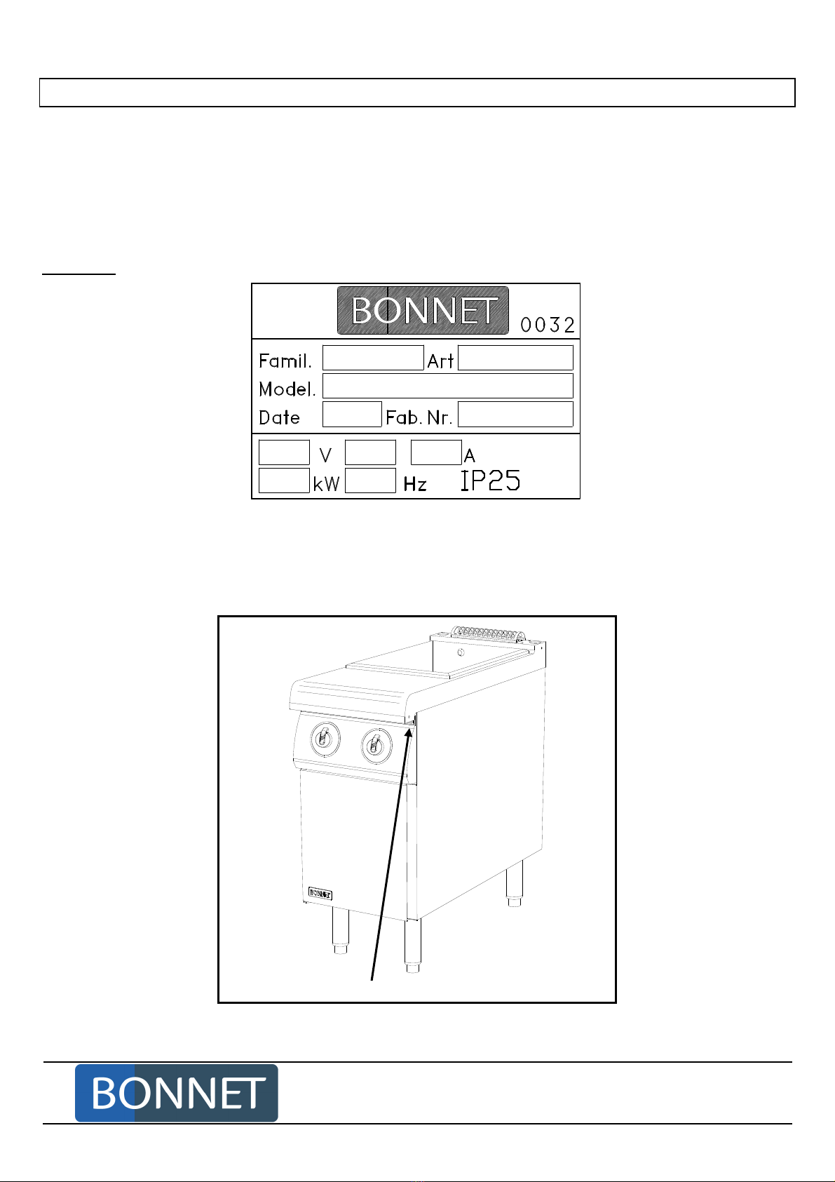
NATURE AND POSITION OF THE CONNECTIONS
See the "Technical characterisitcs" at the beginning of these instructions.
2.1 GENERAL REQUIREMENTS
Aqualified engineer mustcarry out the installation,modificationorrepairof the appliance inaworkmanlike
manner.
These appliances must be installed with sufficient ventilation to prevent the formation of excessive
concentrations of substances noxious for the health in the room in which they are installed.
The equipment is not designed to work in an explosive atmosphere. Due to this, it must not be
installed in a zone subject to ATEX directive.
The appliances must be installed according to the standard EN 1717 and the national regulation in
force relating to water.
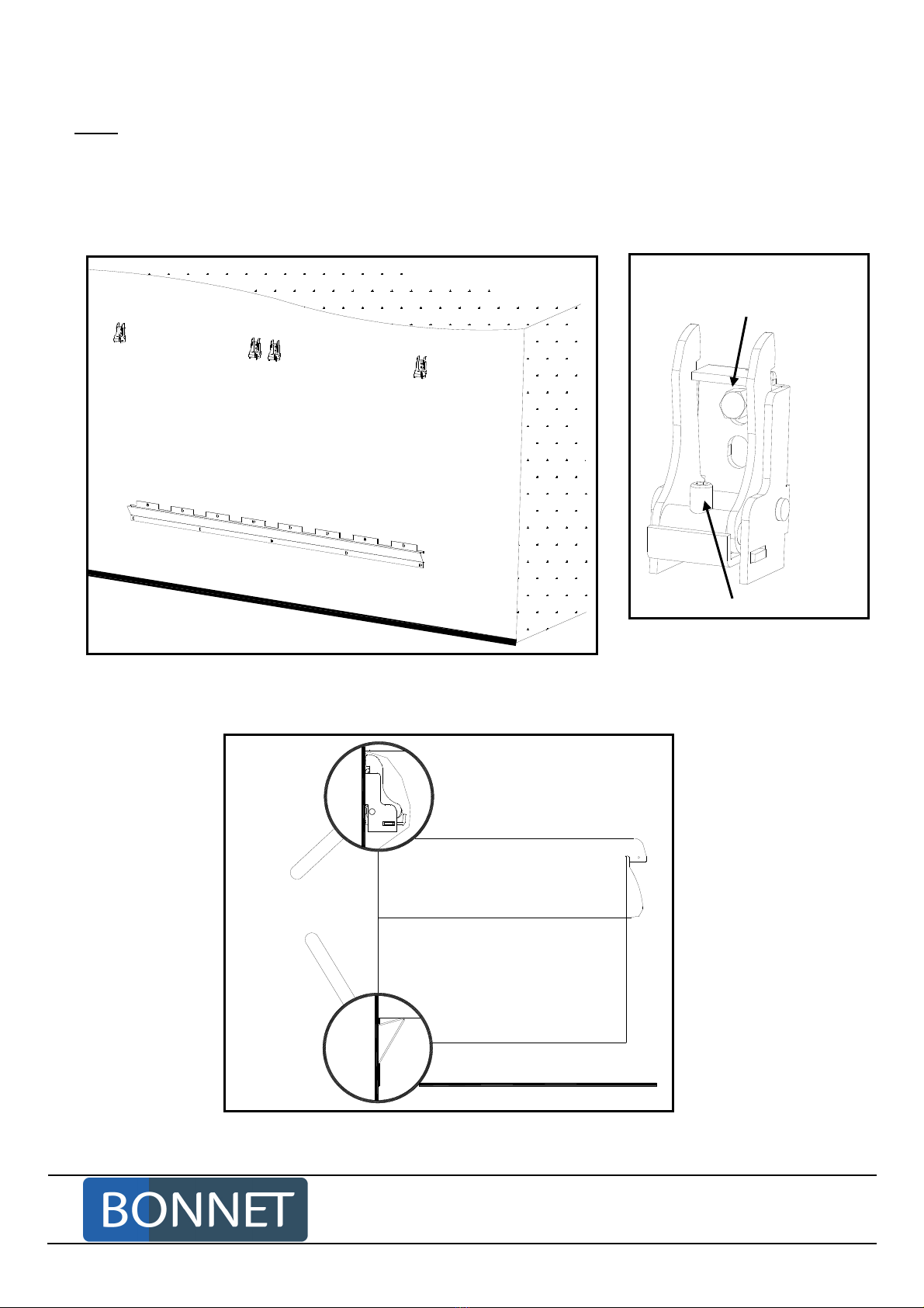
These units must only be placed against a wall or a partition. The latter must be of non-combustible
materials or, if not, must be covered with an appropriate, good insulating and non-combustible
material.
The manufacturer certifies that the packaging meets the provision 94/62/CE (provision relating to
packagings and packaging waste of 12.20.94) and requests that final installer (and user) observes
the rules relating to the removal of the packaging (recycling or reconditioning).
2.2 HANDLING
The appliance should only be handled with adapted lifting equipment.
Should the appliance need to be transported, this must be on its original pallet and it must not be
stacked on other appliances under any circumstances.
If the appliance is to be moved without its pallet, it should be carried and not pulled.
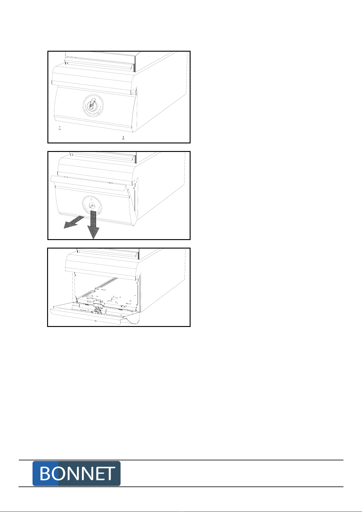
2.3 UNPACKING
Before installation, remove the strapping from the appliance. The individual parts are not bolted down.
Remove the protective plastic film from the stainless steel parts before heating.

Page 6 3BE390723NI – 11/09
BONNET GRANDE CUISINE
Registered Office:
Rue des Frères Lumière - Z.I Mitry Compans
77292 MITRY MORY Cedex
2.4
ACCESS TO THE COMPONENTS PLACED THE FASCIA
- Unscrew both M5 x 16 screws under
the fascia.
1
2
- Tilt the fascia: Slightly pull downwards
then to yourself .
- Put the fascia in locking position:
clamp both lugs into the apertures
foreseen in the fascia.

Page 7 3BE390723NI – 11/09
BONNET GRANDE CUISINE
Registered Office:
Rue des Frères Lumière - Z.I Mitry Compans
77292 MITRY MORY Cedex
3. INSTALLATION: PUTTING IN PLACE
3.1 ASSEMBLY OF CANTILEVER APPLIANCES TO A WALL
Drilling pattern
892
16
212 131
400 800 1000 1200
41 4141 4141 4141 41
100 100
200 100 200 200 200 100100 200 200 200 200 100100 200 200 200 200 200 100
1118918718318
15 385 400 400 400 200 400 400 400 385 15
902
The fixation of a bracket must support a tensile strength of 400 daN (2 brackets for a 400, 800, 1000 or
1200 wide appliance).
It is recommended, for the fixation of cantilever appliances to a concrete wall, to observe the following points:
* The reinforced concrete of the wall must be at least of quality 23 MPA (DTU).
* Use HSA-R M 8x75 plugs or equivalent (2 for cooking tops and 6 for cooking units).
* For the plugs above, each hole must be drilled to diameter 8 mm and, at least, 65 mm deep.
Procedure
- Fix the lower bearing beam of the appliances against the wall.
Warning! Check this bearing beam is properly horizontal.
- Fix the template supplied by two ∅5 screws to the wall. Check horizontality.
902
212 131

Page 8 3BE390723NI – 11/09
BONNET GRANDE CUISINE
Registered Office:
Rue des Frères Lumière - Z.I Mitry Compans
77292 MITRY MORY Cedex
- Drill through the ∅5 fixation holes of the brackets. Use the upper holes (2 brackets per appliance).
Note: In case of impossibility (due to the presence of technical ducts, a metal strengthener in the
wall…), drill through the lower holes in the template.
- Remove the template.
- Increase the bracket fixation holes to diameter ∅8 and, at least, to 65 mm in depth.
- Fix the brackets to the wall. Use HSA-R M 8x75 plugs or equivalent.
- Open the brackets to the maximum by means of the centre screw
Opened bracket
Opening screw
- Put the appliances in place on the brackets and lock them.
Warning! The appliances must rest on the bearing beam.
Fixation screw
Bearing
beam
Bracket

Page 9 3BE390723NI – 11/09
BONNET GRANDE CUISINE
Registered Office:
Rue des Frères Lumière - Z.I Mitry Compans
77292 MITRY MORY Cedex
- Fix the appliances between themselves from behind in the way of collectors by one
HM5
X
16
screw + ø 5 flat
washer.
- Fix the appliances between themselves from the front after having removed the front fascia (see
paragraph 3.4) with one HM5
X
16
screws +
Ø
5 flat washers.
3.2 ASSEMBLY OF THE APPLIANCES ON AN INDIVIDUAL BASE
- Fix the appliances between themselves at the back in the way of collectors by one
HM5
X
16
screw + ø 5 flat
washer.
- Fix the appliances between themselves at the front after having removed the front fascia (see paragraph
3.4) with one HM5
X
16
screws +
Ø
5 flat washers.

Page 10 3BE390723NI – 11/09
BONNET GRANDE CUISINE
Registered Office:
Rue des Frères Lumière - Z.I Mitry Compans
77292 MITRY MORY Cedex
3.3 ASSEMBLY OF THE APPLIANCES ON A COMMON BASE
- Put an appliance on the base, the back parts of the appliance and the base being approximately in
alignment. (The base is is symmetrical, the back and front parts being identical).
- Push the appliance backwards until the hooks made in its bottom slots into the square holes size 25 x 25
foreseen for this purpose.
Hook fixation (detail)
Hook Hole
- Perform these two operations for each appliance put on the same base.
- From front, fix the appliance on the base with two HM 5 x 16 screws + 2 ø 5 flat washers from the underside.
- Fix the appliances between themselves at the back in the way of collectors with one HM5
X
16
screw +
Ø
5 flat
washer.
- Fix the appliances between themselves at the front after having removed the front fascia (see paragraph
3.4) with one HM5
X
16
screws +
Ø
5 flat washers.

Page 11 3BE390723NI – 11/09
BONNET GRANDE CUISINE
Registered Office:
Rue des Frères Lumière - Z.I Mitry Compans
77292 MITRY MORY Cedex
3.4 ASSEMBLY OF THE APPLIANCES ON A MASONRY BASE
Dimension of the masonry base for wall or central stove
Am
Ls
Ac
Wall
Centrally
(side view)(side view)
(front view)
Full tiled base
Lf: Stove width
Stove depth Stove depth Stove depth
Full tiled base Full tiled base Full tiled base
1 cm/m maximum slope 1 cm/m maximum slope 1 cm/m maximum slope
Finished
height with
tiled front
Finished
height with
tiled front
Dimension of the base
Range Am
Base depth as a wall
version
Ac
Base depth as a central
version
Ls
Base length Finished height,
completely tiled
on the front
Optimum 700
520 1040 Lf-50 110
Optimum 900
710 1420 Lf-50 110
The technical compartment is compulsory if the switch-off tap, the shut-off valve, or the reducing valve
are in the stove.
There are two possibilities:
1) Neutral top on a 200 or 400 wide technical compartment.
2) Cupboard foreseen for taps and sized 400 with all possibilities of cooking or neutral tops
except induction.

Page 12 3BE390723NI – 11/09
BONNET GRANDE CUISINE
Registered Office:
Rue des Frères Lumière - Z.I Mitry Compans
77292 MITRY MORY Cedex
Assembly of the appliances on a masonry base
Put the appliances in place on the masonry base.
Note: If the appliances are delivered separately from the base, install the appliances on one or more bases
space 2000.
Connect electrical supply to the appliances (see paragraph 5: Installation: Connections)
Assemble the appliances between themselves.
- Fix the appliances between themselves at the back in the way of collectors with one HM5
X
16
screw
+
Ø
5
flat washer.
- Fix the appliances between themselves at the front having removed the fascia (see paragraph 2.2.3)
with two HM5
X
16
screws
+
Ø
5 flat washers.
Connect gas, water and drainage lines to the appliances.
Fit the trimming plinths. One front plinth per space 2000 base and one right and left end trimming plinth per
stove, depending on order.
- Assemble one or more front plinths with junctions (depending on the quantity of bases) (2 screws per plinth).
- Fix one or more front plinths and ) onto one or more bases (two screws at least per plinth).
- Fix the back part (on the end appliances before their final installation) on the base with the hex
head screw ().
- Fix the right and left end trimming kits () (2 front screws and 1 back screw).
1
24
3
Base
height
at front
Appliance
Ventilation
Trimming
plinth
Base space
2000
Possibility to lay piping
on the front

Page 13 3BE390723NI – 11/09
BONNET GRANDE CUISINE
Registered Office:
Rue des Frères Lumière - Z.I Mitry Compans
77292 MITRY MORY Cedex
4. INSTALLATION: CONNECTIONS
4.1 ELECTRIC CONNECTION
Location of the equipotentiality terminal
Electric connection is carried out from behind of the appliance, whatever the model.
- Loosen the fixation screw and remove the cover of the connecting box.
- Introduce the cable through the gland.
- Tighten the gland.
- Connect the wires.
- Put the cover back in place and fix it.
- Connect the equipotential link to the terminal foreseen for the purpose.
•Only use supply cables of the H07 RN-F type with section :
Voltages Sections
230 V 3 a.c. 4 x 4 mm
2
400 V 3N a.c.
5 x 2.5 mm
2
Foresee an omnipolar shut off device patented for safety of personnel (with a distance between
contacts of at least 3 mm when opened).
The installation must meet the national rules in force (France: NFC 15.100).
The appliance must be connected to the earth. The different electric appliances must also be
connected by means of an equipotential line (all metallic structures to the same voltage) by means of a
terminal provided for this purpose and located beside the connecting gland.
The builder denies all responsibility in the case where the instructions above are not observed.

Page 14 3BE390723NI – 11/09
BONNET GRANDE CUISINE
Registered Office:
Rue des Frères Lumière - Z.I Mitry Compans
77292 MITRY MORY Cedex
4.2 WATER CONNECTION
- Hot water.
- Minimum pressure 2.5 bars, maximum 6 bars.
- Maximum temperature for hot water 60°C.
- Connection of flexible hose of diameter 15/21 (1/2").
- Foresee a shut off valve in the vicinity.
4.3 DRAINAGE CONNECTION
Drained water is at a temperature of 100°C, due to this exclude the PVC-type materials.
50 mm minimum
IMPORTANT: In the framework of protection against pollution of mains water, IT IS STRICTLY PROHIBITED
TO CONNECT THE APPLIANCE DIRECTLY TO THE OUTER SEWAGE SYSTEM (in a tight
manner). So as to avoid any rise of sewage water into the enclosure of the recipient, a vent to
open air must be foreseen between the drainage system of the appliance and the outer
sewage line.
The drain must include a siphon to fight against any return of bad smells.
Recommended solution:
50 mm
Foresee piping
depending on the
reservation
Ø100 siphon type plug
(under the slab) or gutter
Other manuals for OPTIMUM 700
6
This manual suits for next models
1
Table of contents
Other Bonnet Pasta Maker manuals