Bonnet P072825 User manual

Toque Blanche
Grande Carte
PASTA COOKER
MANUFACTURER’S INSTRUCTIONS
Part A: Technical data
Part B: Installation manual
-
WARNING -
•
Installation and repairs must be carried out by personnel approved by the manufacturer and in
accordance with current regulations and standards.
•
If any modifications are made the manufacturer can accept no responsibility whatsoever.
•
These appliances must be used in a well-ventilated area.
•
Read the notice carefully before installation.
•
The unit must be kept on its base for handling until it is in it’s final location.
N° 390 268
9

Page 1
BONNET CIDELCEM GRANDE CUISINE
Siége social:
Rue des Frères Lumière - Z.I Mitry Compans
77292 MITRY MORY Cedex
CONTENTS
PASTA COOKER
A) TECHNICAL DATA ………………………..................................................2
B) INSTALLATION MANUAL
1. Location of the identification plate .………........................................... 4
2. Installation: General features …………….……………..………………... 5
2.1 General requirements …….……….……...….……...…...………..... 5
2.2 Handling ……….....…………………………………..….……………. 5
2.3 Unpacking ………...……..…………………………….………….…... 5
2.4 Access to components behind the front panel …………….…….... 5
2.5 to 2.7 Installation ...…………..………………………..…………….... 7
3. Installation: connection ……………………………………………………. 12
3.1 Electrical connection …………………..…...……...………..……..... 12
3.2 Water connection ………...…..…...……………………………..…... 12
3.3 Drain connection ………...…..…...……………………………..…... 13
4. Electrical circuits ……………………………………………………...……. 14
5. Hydraulic circuits ………………………………………………...…...……. 16
6. Other spare parts …………………...…………………………….....……. 17
7. Emergency spare parts …………………...….……………….……..……. 18

Page 2
BONNET CIDELCEM GRANDE CUISINE
Siége social:
Rue des Frères Lumière - Z.I Mitry Compans
77292 MITRY MORY Cedex
A: TECHNICAL DATA
Toque Blanche, Pasta cooker
P072323
DIMENSIONS (mm)
External Width 400; Height 900; Depth 730
Baskets 290 x 90 x 16
CAPACITY (mm)
Well 20 litres
Baskets 0.5 kg
PACKAGING (mm)
Height 1200
Width 500
Depth 840
WEIGHT (KG) 40
ELECTRICITY
Voltage I (Max) P (kw
230 V 3a.c. Three phase 230V+E 15.1 6
400 V 3Na.c. Three phase 400V+N+E 8.7 6
HOT WATER Pressure (Min/Max) 250/600 kPa or 2.5/6 bar
Flexible connection 12/17mm Ø
DRAIN 18 mm Ø Compression
Connection 18 mm pipe
CONSTRUCTION
Casing Stainless 18-10
Facia Stainless 18-10
Well Stainless 18-10
APPLIANCE TYPE Free standing (against a wall or other appliance)
ELECTRICAL CONNECTION
200 mm from floor
Non contractual document Edition 06/2000 – EN177

Page 3
BONNET CIDELCEM GRANDE CUISINE
Siége social:
Rue des Frères Lumière - Z.I Mitry Compans
77292 MITRY MORY Cedex
Grande carte, Pasta cooker
P072825
DIMENSIONS (mm)
External Width 400; Height 900; Depth 920
Baskets 290 x 90 x 160
CAPACITY (mm)
Well 20 litres
Baskets 0.5 kg
PACKAGING (mm)
Height 1200
Width 500
Depth 1030
WEIGHT (KG) 43
ELECTRICITY
Voltage I (Max) P (kw)
230 V 3a.c. Three phase 230V+E 15.1 6
400 V 3Na.c. Three phase 400V+N+E 8.7 6
HOT WATER Pressure (Min/Max) 250/600 kPa or 2.5/6 bar
Flexible connection 12/17mm Ø
DRAIN 18 mm Ø Compression
Connection 18 mm pipe
CONSTRUCTION
Casing Stainless 18-10
Facia Stainless 18-10
Well Stainless 18-10
APPLIANCE TYPE Free standing (against a wall or other appliance)
ELECTRICAL CONNECTION
200 mm from floor
Non contractual document Edition 06/2000 – EN178

Page 4
BONNET CIDELCEM GRANDE CUISINE
Siége social:
Rue des Frères Lumière - Z.I Mitry Compans
77292 MITRY MORY Cedex
B: INSTALLATION MANUAL
1. IDENTIFICATION PLATE
The identification plates are fixed on the inside of the cupboard door (See diagram below).
In any correspondence about your equipment, please quote:
- The model number (Model.)
- The serial number (Fab.Nr).
- The date (Date).
Location of the identification plate
Identification plate

Page 5
BONNET CIDELCEM GRANDE CUISINE
Siége social:
Rue des Frères Lumière - Z.I Mitry Compans
77292 MITRY MORY Cedex
2. INSTALLATION: GENERAL FEATURES
TYPE AND POSITION OF CONNECTIONS
See "Technical data" at the beginning of these instructions.
2.1 GENERAL REQUIREMENTS
The installation or repair of this appliance should be carried out according to current regulations by
a qualified engineer.
These appliances are intended for professional use, they must only be used by trained personnel.
The appliance must be installed in compliance with the appropriate standards, in an adequately
ventilated area.
These appliances should ideally be against a wall. The latter must be of non-combustible materials
or, if not, should be covered with an appropriate material, good insulator, non-combustible.
2.2 HANDLING
The appliance should be handled with specialised lifting equipment only.
If the appliance is to be transported, this must be done on its original pallet and it must not be stacked
in any circumstance.
If the appliance is to be moved without its pallet, it should be carried and not dragged.
2.3 UNPACKING
Before installation, remove the strapping. The individual parts are not bolted down.
Remove plastic coating from stainless steel before heating the appliance.
2.4 ACCESS TO COMPONENTS BEHIND THE FRONT PANEL
a) Removing the facia
- Slacken the control knobs fixing
screws.
- Remove electrical and water inlet
control knobs.

Page 6
BONNET CIDELCEM GRANDE CUISINE
Siége social:
Rue des Frères Lumière - Z.I Mitry Compans
77292 MITRY MORY Cedex
- Unscrew and remove the 2 M5 X
16 screws under the fascia.
- Remove front to do so, lift front 1),
then pull the bottom edge
outwards and downwards (2).
b) Access to electrical components
- Remove the 2 fixing screws from
the top left and right of the control
rack.
- Swivel control rack outwards.
For re-assembly, reverse the above operations.

Page 7
BONNET CIDELCEM GRANDE CUISINE
Siége social:
Rue des Frères Lumière - Z.I Mitry Compans
77292 MITRY MORY Cedex
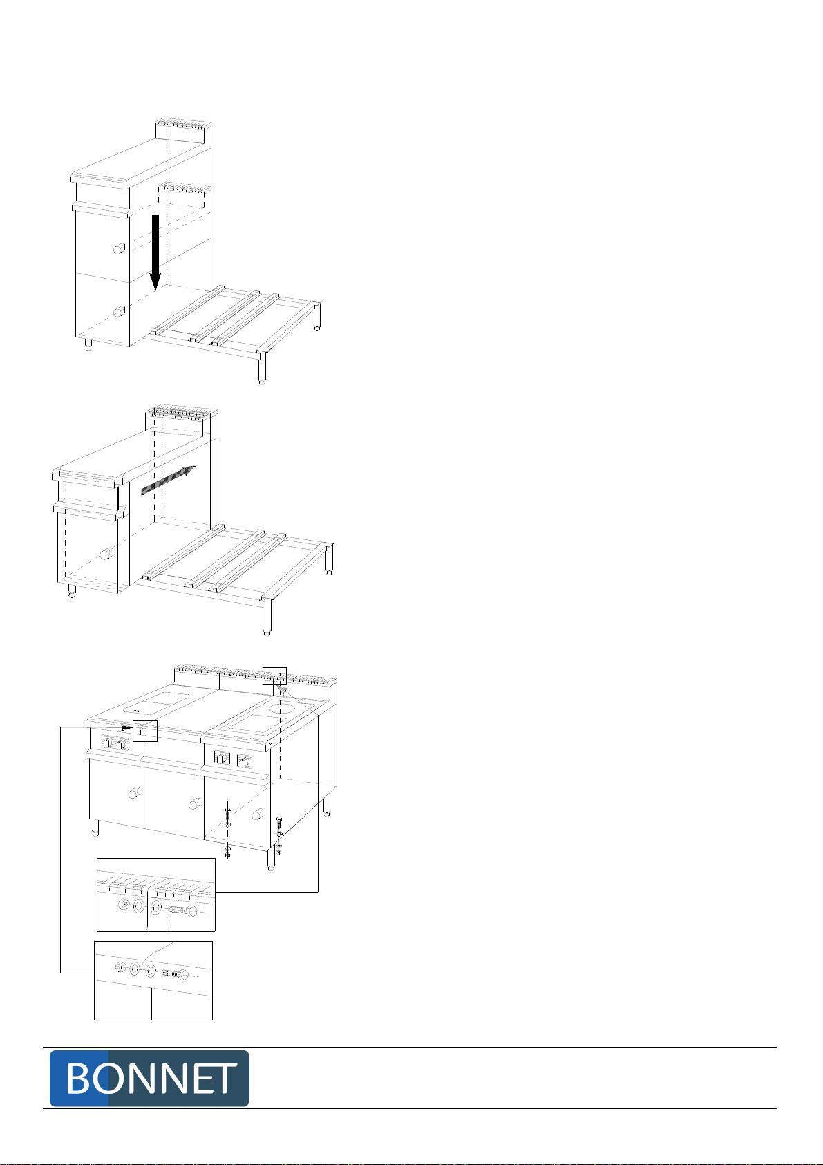
2.5 ASSEMBLY ONTO A SINGLE UNDERFRAME
Place appliance on the underframe, with rear of
appliance and the underframe approximately aligned. (The
underframe is symmetric front and rear are identical).
Push the unit backwards until the hooks in the base
locate into the 25mm square holes provided
Repeat these two operations for each appliance to be fitted
on the same underframe.
Fix the front to the underframe with HM 5 x 16mm nuts
and bolts + 2 washers either inside when the appliance
design makes this possible (cupboard) or from underneath.
Connect the units to each other:
1) at the rear inside the vent again with 5 x 16mm
fixings irrespective of the type of equipment.
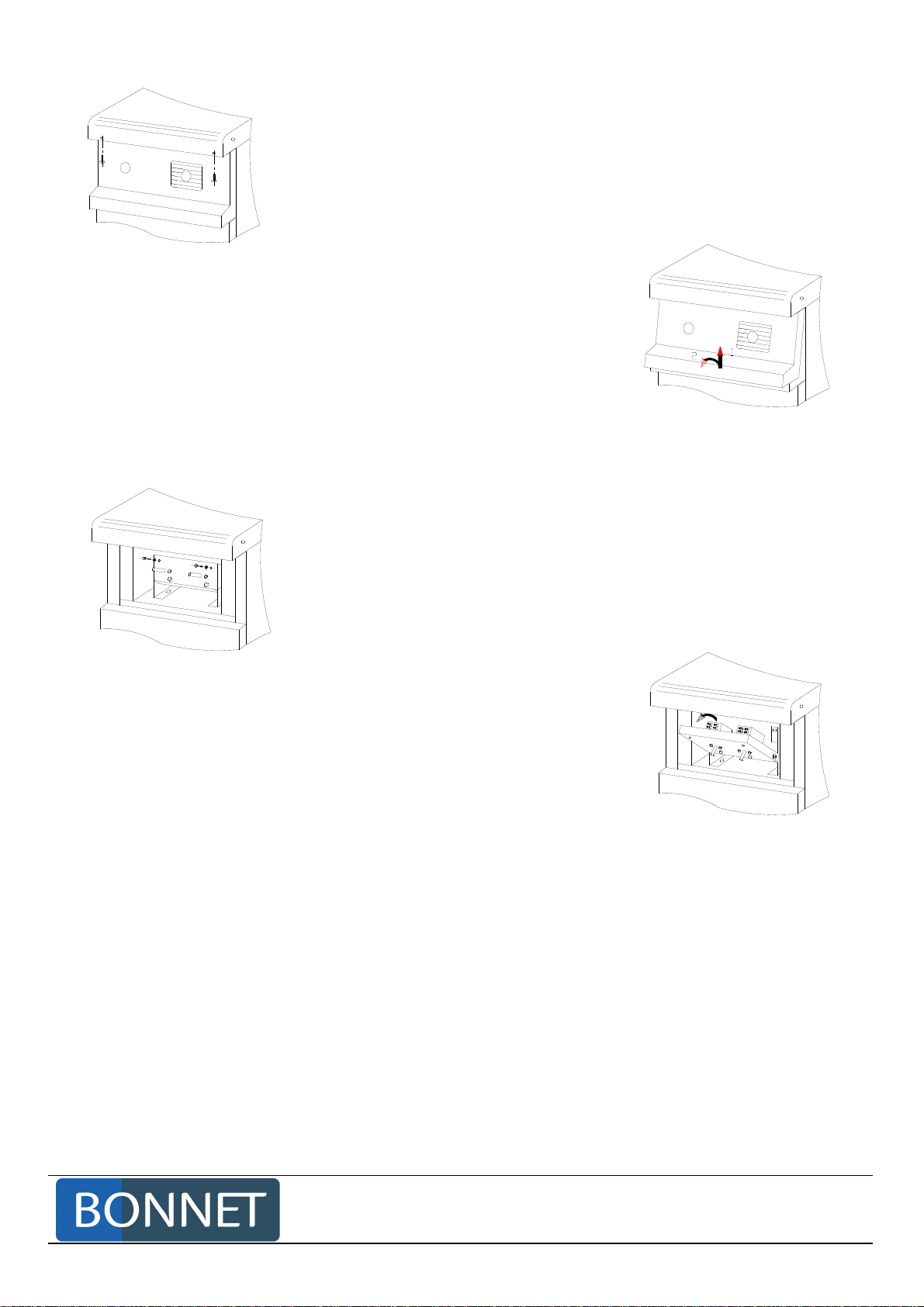
2) at front inside the facia after removing the front of the
appliance (see section).
- Use HM5 x 16mm bolts + 5mm Ø washers for
boiling pan or deep fat fryer connected to
cooking unit (a captive nut is located in the side
rails behind the facia).
- Use HM5 x 16mm nuts and bolts + 5mm Ø
washer to connect cooking units together,
having removed the M5 captive nut from one of
the 2 appliances (from the screw side), using a
screwdriver.

Page 8
BONNET CIDELCEM GRANDE CUISINE
Siége social:
Rue des Frères Lumière - Z.I Mitry Compans
77292 MITRY MORY Cedex
2.6 ASSEMBLY ON AN INDIVIDUAL UNDERFRAME
Fasten appliances together.
1) at the back through the flue using HM 5 x 16 bolts for all types of appliance.
2) at the front behind the facia (see section before)
- Use HM5 x 16mm nuts and bolts + 5mm Ø washers to connect cooking units together, having
removed the M5 captive nut from one of the 2 appliances (from the screw side), using a
screwdriver.
3) behind legs using pliers:
a) Position pliers against the fold
b) Hand tighten as far as possible
c) Finish tightening with HM5 x 60 bolt

Page 9
BONNET CIDELCEM GRANDE CUISINE
Siége social:
Rue des Frères Lumière - Z.I Mitry Compans
77292 MITRY MORY Cedex
2.7 INSTALLATION OF COOKING UNITS ONTO A PLINTH
2.7.1 WALL SUITE ON A PLINTH
The technical compartment is recommended if the stop cocks, isolators and governors are to be
housed in the range.
Two solutions are possible:
1) The range must include a 400mm cupboard with any type of cooking or neutral top possible,
except induction.
2) A Technical compartment at the end of the range (250mm wide) with neutral top (access panel
in the end).
Toque Blanche Grande Carte
Length A
N
1 400 +
N
2 800 +
N
3 1200,
ETC N
1 400 +
N
2 800 +
N
3 1200,
ETC
Length B 710 900
Length C 360 550
Length D 210 400
Length E 100 290

Page 10
BONNET CIDELCEM GRANDE CUISINE
Siége social:
Rue des Frères Lumière - Z.I Mitry Compans
77292 MITRY MORY Cedex
2.7.2 ISLAND RANGE ON PLINTH
The technical compartment is recommended if the stop cocks, isolators and governors are to be
housed in the range.
Two solutions are possible:
1) The range must include a 400mm cupboard with any type of cooking or neutral top possible
except induction.
2) A Technical compartment at the end of the range (250mm wide) with neutral top (access panel
in the end).
Toque Blanche Grande Carte
Length A
N
1 400 +
N
2 800 +
N
3 1200,
ETC N
1 400 +
N
2 800 +
N
3 1200,
ETC
Length B 1420 1800
Length C 720 1100
Length D 520 900
Length E 100 290

Page 11
BONNET CIDELCEM GRANDE CUISINE
Siége social:
Rue des Frères Lumière - Z.I Mitry Compans
77292 MITRY MORY Cedex
2.9.3 FITTING EQUIPMENT TO THE PLINTH
- Run the gas float within the recess in the plinth.
- Place and centre the stainless steel frame on the plinth and fasten with anchor bolts.
The stainless steel frame comprises sub-assemblies of lengths 800, 1200 and 1600 enabling frames to
be made to requisite lengths.
Sheet steel templates are delivered with the stainless steel frames, enabling sub-assemblies to be
positioned and fastened together quickly and accurately.
- Adjust level using adjusting screws provided. (see diagram above)
- Assemble appliances onto base (follow procedure).
- Connect gas, electricity and water, and check for leaks.
- Fasten ventilation covers to the ends of the range (use 2 screws).
NOTE: The diagram aboveshows a wall plinth. In the case of an island plinth, the base is symmetric on both
sides: assembly is therefore the same.

Page 12
BONNET CIDELCEM GRANDE CUISINE
Siége social:
Rue des Frères Lumière - Z.I Mitry Compans
77292 MITRY MORY Cedex
3. INSTALLATION: CONNECTIONS
3.1 ELECTRICAL CONNECTION
Earth bonding point
Whatever the model the electrical connection is at the rear.
- Remove the cover
- Feed cable through cable gland and tighten
- Connect up wires
- Connect earth to bonding point provided.
- Replace cover.
IMPORTANT: Only use power supply cables of H07 RNF type with section as indicated below:
Voltage Cable
380 / 415 4 x 2.5 mm
2
220 / 240 4 x 4 mm
2
Provide suitable multipolar isolator (with a contact opening distance of at least 3 mm).
The installation must comply with current electrical regulations (France NFC 15.100).
The appliance must be earthed.The various electric appliances must also be earth bonded (every
metal part on the same voltage) via the terminal provided located next to connection cord-grip.
The manufacturer can not be held responsible in case of failure to heed these instructions.
3.2 WATER CONNECTION
- Hot water.
- Pressure min 2.5 bar, max 6 bar.
- Flexible connection 12/17 ∅
- Provide a local stop cock.
3.3 DRAIN CONNECTION

Page 13
BONNET CIDELCEM GRANDE CUISINE
Siége social:
Rue des Frères Lumière - Z.I Mitry Compans
77292 MITRY MORY Cedex
This water could be at high temperature (98°C) so the use of PVC is not recommended
IMPORTANT: As part of the general protection against water network pollution DO NOT CONNECT THE
APPLIANCE DIRECTLY TO DRAIN. In order to avoid any waste water entering the cooking
cell an air break must be installed BETWEEN the appliance and the external drain.
The drain should be trpped to avoid adours.
Recommended method:

Page 14
BONNET CIDELCEM GRANDE CUISINE
Siége social:
Rue des Frères Lumière - Z.I Mitry Compans
77292 MITRY MORY Cedex
4. ELECTRICAL COIRCUITS
4.1 CONTROL DIAGRAM
4.2 POWER DIAGRAM 230V Three phase
4.3 POWER DIAGRAM 400V Three phase

Page 15
BONNET CIDELCEM GRANDE CUISINE
Siége social:
Rue des Frères Lumière - Z.I Mitry Compans
77292 MITRY MORY Cedex
4.4 PARTS LIST
Ref. Designation Quantity Code
As Regulator 1 301 200
Fr Three-pole thermostat 1 301 055
Hr Indicator 1 308 334
Kr Contactor 1 300 697
Rc Immersion heaters 1 303 122

Page 16
BONNET CIDELCEM GRANDE CUISINE
Siége social:
Rue des Frères Lumière - Z.I Mitry Compans
77292 MITRY MORY Cedex
5. HYDRAULIC CIRCUITS
5.1 DIAGRAM OF HOT WATER INLET
5.2 PARTS LIST
REF. DESIGNATION CHARACTERISTICS CODE
1Handle 138 184
2Seals 366 369
3Tap head ½ inch 313 052
4Tap Body 381 237
5Spout 313 136
6Hexagon lock nut 3/8 317 879
7Brass olive ∅10 317 877
8Olive nut ∅10-318 317 878
9Water inlet flexible 316 140

Page 17
BONNET CIDELCEM GRANDE CUISINE
Siége social:
Rue des Frères Lumière - Z.I Mitry Compans
77292 MITRY MORY Cedex
6. OTHER SPARE PARTS
CODE
REF. DESIGNATION Toque Blanche Grande Carte
1VENT COVER 14 31 95 14 31 95
2CUPBOARD HANDLE CAP 384 574 384 574
3CUPBOARD DOOR HANDLE 384 572 384 572
4ADJUSTABLE FOOT (complete) 384 575 384 575
5LABEL 308 931 308 931
6WATER INLET KNOB 138 184 138 184
7CONTROL KNOB 13 28 43 13 28 43
CONTROL KNOB GASKET 366 369 366 369
CUPBOARD DOOR Left door
Right door 13 05 64
13 05 65 13 05 64
13 05 65
8
CUPBOARD DOOR MAGNET ALL MODELS 384 110 384 110
9BASKETS 386 166 386 166
10 FILTER GRILL 39 854M 39 797M
11 BASKET SUPPORT PLATE 39 792 39 792
12 SPOUT 313 136 313 136
13 TEE 317 959 317 959
14 IMMERSION HEATERS 303 122 303 122
15 DRAIN TAP CIM 205 MP 3/4"-3/4" 313 056 313 056

Page 18
BONNET CIDELCEM GRANDE CUISINE
Siége social:
Rue des Frères Lumière - Z.I Mitry Compans
77292 MITRY MORY Cedex
7. EMERGENCY SPARE PARTS
CODE
DESIGNATION Toque Blanche Grande Carte
IMMERSION HEATERS 303 122 303 122
CONTROL KNOB 13 28 43 13 28 43
CONTROL KNOB GASKET 366 369 366 369
DRAIN TAP CIM 205 MP 3/4"-3/4" 313 056 313 056
Table of contents
Other Bonnet Pasta Maker manuals