Kerbl Wellington User manual

Stationäre Schafanlage „Wellington“ 1-speed, mit Handstück Trident Pro
Art. 18157, 18151
Allen Benutzern der stationären Schafanlage „Wellington“ wird empfohlen vor Gebrauch die Anleitung genauestens zu lesen.
Bedienungsanleitung
Vorsicht:
• Das Scherhandstück ist mit drei zweireihigen Präzisionslagern ausgerüstet, die nicht durch allgemeine Lager ersetzt werden dürfen.
• bei Einbau des Reparatur-Sets, klemmen Sie die Schafanlage nicht in einen Schraubstock! Alle Arbeiten sollten auf einer trockenen,
sauberen Holzunterlage durchgeführt werden oder das Handstück muss während der Arbeit in den Händen gehalten werden.
• Stellen Sie außerdem sicher, dass das Handstück vor dem Lösen der Spannmutter ausgekuppelt ist
• Zerlegen Sie niemals das Handstück, es sei denn, Teile müssen ausgetauscht werden!
• Überprüfen Sie, ob die Druckgabeln in den entsprechenden Löchern gesichert sind, ansonsten kann die nötige Spannung
nicht erzeugt werden.
• Stellen Sie sicher, dass das Gelenkstück mit dem Handstück verbunden ist, wenn Sie eine biegsame Welle verwenden
Schmierung
Ölen Sie jede halbe Stunde!
Geben Sie ein paar Tropfen eines hochwertigen Öls auf Ober- und Untermesser, Gabelkopfspitze, Zahnräder und rund um die
Exenterrolle (durch das Öl-Loch auf der Spitze des Handstücks). Lösen Sie die Spannmutter und bringen Sie das Handstück in
eine vertikale Position, anschließend geben Sie etwas Öl in die Druckbuchse, dann heben Sie den Gabelkopf an und bringen
etwas Öl in die Innenseite um den Kugelkopfdeckel zu ölen. (siehe Abbildung 1)
Tägliche Schmierung
Entfernen Sie die Druckbuchse und bringen Sie eine großzügige Menge Fett an der Innenseite der Hülse an.
Bringen Sie auch eine kleine Menge Fett an den hinteren Zähnen an.
Wöchentliche Schmierung
Die Druckgabeln entfernen, eine großzügige Menge Schmiermittel in die Löcher am Gabelkörper geben und die Druckgabeln
wieder anbringen. Sicherstellen, dass sie im Loch befestigt sind. Die Gelenkbaugruppe durch Abschrauben der Zähne abnehmen,
eine kleine Menge Schmiermittel in die ringförmigen Zwischenräume zwischen der Buchse (25) und der Reguliermutter (28) geben.
Das Schmiermittel muss hochwertig und für den Einsatz bei Temperaturen bis zu 120 °C geeignet sein. Regelmäßiges Schmieren
verlängert die Lebensdauer Ihres Scherhandstücks (siehe Abb. 2).
Keine Schmierung für Lager
Kugellager sind in das Handstück eingebaut und müssen nicht geölt oder gefettet werden.
Vorsicht:
Kein Öl oder Fett zwischen Spannmutter und Druckbuchse anbringen,
da dies zu einem Verlust der Spannung führt!
Abb. 1
Abb. 2
18157=BA_Wellington_Trident_Pro_0417

Auswahl der geeigneten Ober- und Untermesser
Ober- und Untermesser spielen eine wichtige Rolle bei der Scherung. Daher ist es wichtig, das entsprechende
Untermesser für den jeweiligen Einsatz zu wählen.
Bei der Auswahl des richtigen Untermessers ist es wichtig, auf Form, Fase und Breite des Kamms zu achten.
(siehe Abbildung 3)
Unter normalen Scherbedingungen:
1. Untermesser mit kurzer Fase: Die kurze Fase wird hauptsächlich verwendet, wenn die Scherung am Einfachsten ist
und die Schafe in einem bestmöglichen Zustand für eine Scherung sind
2. Untermesser mit mittlerer Fase: Die mittlere Fase wird bei der Mehrheit der Kreuzungen eingesetzt und ist für die
meisten Arten von Wolle geeignet.
3. Untermesser mit langer Fase: Die lange Fase eignet sich besonders für Schafe mit feiner Wolle und wird häufig bei
klebriger Wolle oder bei frühzeitiger Scherung verwendet
Einstellung von Ober- und Untermesser:
Legen Sie einen Ober- und Untermesser auf das Handstück. Die Schrauben leicht anziehen, sodass man das Untermesser noch
bewegen kann.
Stellen Sie sicher, dass die mittleren Zähne des Messers mindestens 1,5 bis 2,0 mm vor dem Handstück sind.
Anziehen der Schrauben mit dem mitgelieferten Schraubenzieher. (siehe Abbildung 4)
Die Druckgabeln:
Stellen Sie sicher, dass jeder der beiden Druckgabeln frei drehbar in der Gabel ist. Entfernen Sie die Druckgabeln einmal in der
Woche. Reinigen Sie die diese und die Vorderseite des Gabelkopfs gründlich. Ziehen Sie die Druckgabeln per Hand oder Zange
heraus. Geben Sie immer eine kleine Menge an Fett in die Löcher der Gabel, wenn Sie die Hühnerfüße entfernen. Wenn der Kegel
und die Spitze auf der äußeren Seite der Hühnerfüße abgenutzt ist, muss diese so schnell wie möglich ersetzt werden.
Anpressdruck:
Jedes Ende der Spannbuchse ist unterschiedlich groß. Das größere Ende passt in die Gabelkopfspitze und das kleinere Ende in die
Druckbuchse. Erhöhen Sie den Druck auf das Ober- und Untermesser durch Drehen der Spannmutter. Wenn die Spannmutter
übermäßig festgezogen wird, werden Handstück, Ober- und Untermesser schnell überhitzt. Dies führt auch dazu, dass Ober- und
Untermesser nicht richtig schneiden. Wenn die Maschine nicht mehr richtig schneidet, ersetzen sie das Ober- und Untermesser
mit neu geschliffenen. Wenn keine ausreichende Spannung erzeugt wird, ziehen Sie in Erwägung, den abgenutzten Druckstift, die
Gabelkopfspitze und die Druckbuchse zu erneuern.
Schraube:
Die Haltefeder für die Druckgabeln ist am Gabelkopf durch eine Schraube fixiert und darf nicht lose sein.
Entfernen und Ersetzen des Gabelkopfs:
Gesamte Baugruppe und Exenterrolle entfernen
Abb. 3
Abb. 4

Vorgehen bei der Demontage:
Der Gabel-Körper kann ohne Entfernen der Kugelkopfschraube entfernt werden. Zuerst lösen Sie die Spannmutter, dann entfernen
Sie den Druckstift und die Spannbuchse; anschließend die Sicherungsschraube hinter der Spannmutter und den Gabelkopf mit der
Exenterrolle.
Ersetzen des Gabelkopfs:
Entfernen Sie die Schmierkappe auf der Spitze des Handstücks. Bringen Sie eine kleine Menge Fett auf die Exenterrolle (Kugel) und
den Laufring des Gabelkopfs. Bringen Sie die Rolle auf die Kugelwelle (Stift) mit einem Stift, einem Schraubenzieher oder ähnlichen
Dingen an. Stellen Sie sicher, dass die flache Seite der Walze der Kurbelachse zugewandt ist. Bringen Sie das Kurbel- und Rollenlager
in der unteren Position des Handstücks an.
Führen Sie den Gabelkopf über die Vorderseite in das Handstück und über die Rolle. Nachdem sie gründlich geprüft haben, ob der
Kugelkopfdeckel korrekt auf dem Kugelkopfschraube sitzt, bringen Sie die Sicherungsschraube an und ziehen Sie sie fest.
Einstellung der Kugelkopfschraube:
Die Kugelkopfschraube ist bereits in der Produktion richtig eingestellt werden und ist für jede Messerdicke
geeignet. Wenn diese neu eingestellt werden muss, verwenden Sie ein halb abgenutztes Obermesser (ca. 3,5mm)
und ein beliebig dickes Untermesser, drehen Sie die Exenterrolle auf der Exenterwelle an die oberste Position und
stellen Sie die Kugelkopfschraube durch eine der folgenden Methoden ein:
• Einstellen von Hand:
Lösen Sie die Kugelkopfschraube schrauben Sie diese rein oder raus um den Abstand von der Rollenoberseite zur obersten Fläche
des Laufrings des Gabelkopfs auf 3,65mm einzustellen. Ziehen sie die Mutter für die Kugelkopfschraube wieder an
(siehe Abbildung 5)
• Einstellung mit Hilfe der Einstelllehre:
(Die Einstelllehre ist speziell gefertigt für die Einstellung der Kugelkopfschraube)
Lösen Sie die Schrauben und halten Sie die Lehre wie in der Abbildung, so dass im Winkel von 90° zum Handstück steht.
Drehen Sie die Kugelkopfschraube, bis sich das Mittelstück der Lehre auf gleicher Höhe mit dem Außenteil befindet.
Ziehen Sie die Mutter für die Kugelkopfschraube nach. (siehe Abbildung 6)
Abb. 5
Abb. 6

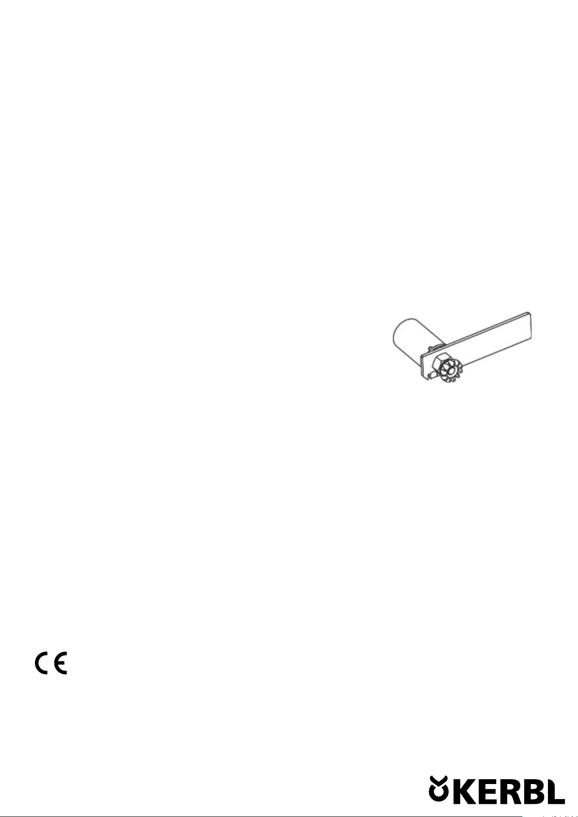
Einstellen des Sicherungsrings für die Reguliermutter (Spannmutter):
Bei der Montage der Bolzenrückholfeder in die Drehmuffe, stellen Sie sicher, dass die große Biegung der Feder direkt im
Uhrzeigersinn angeordnet ist, wenn man von oben auf das Handstück schaut.
Platzieren Sie die Feder über der Drehmuffe und stecken sie das kleinere, gebogene Ende in das Loch.
Stellen Sie sicher, dass die Feder richtig in der Nut der Drehmuffe sitzt.
Vorsicht: Das Fehlen der Rückholfeder führt zum Verlust der Spannung und kann außerdem Schäden am Handstück verursachen!
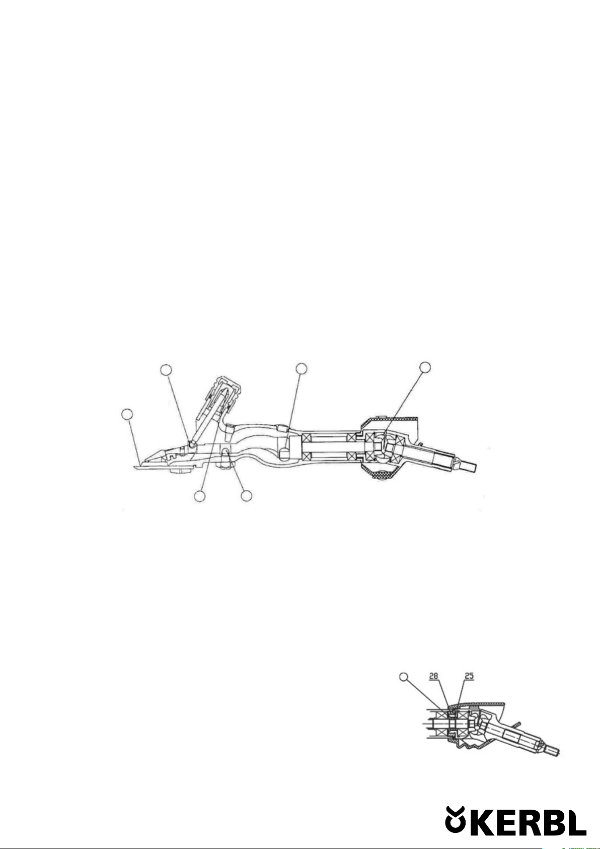
Entfernen der Inneren und Äußeren Gelenkstücke:
Entfernen Sie die Kappe der Ölbohrung und stecken Sie einen Schraubenzieher durch das Loch, um die Exenterwelle zu fixieren.
Lösen Sie anschließend die Zahnräder mit einem geeigneten Schraubenschlüssel. Sie können dann die inneren und äußeren Gelenke
aus dem Griff per Hand entfernen.
Schmieren der Federdeckel:
Die Federdeckel halten nicht nur den Schmutz und Staub fern, sondern tragen auch das meiste Gewicht bei der Bewegung. Ersetzen
Sie diese sofort, wenn Verschleißerscheinungen auftreten. Um die Federdeckel abzunehmen, schieben Sie einen Schraubenzieher
unter Feder und heben Sie diese aus dem Gelenkstück heraus. Entfernen Sie den Federdeckel, schmieren Sie diesen neu und stecken
Sie ihn anschließend wieder an ihren ursprünglichen Ort. Die Federdeckel sollten regelmäßig geschmiert werden.
Vorsicht: Vergewissern Sie sich, dass die Gelenkfeder nicht lose ist. Anderenfalls ist diese sofort zu ersetzen.
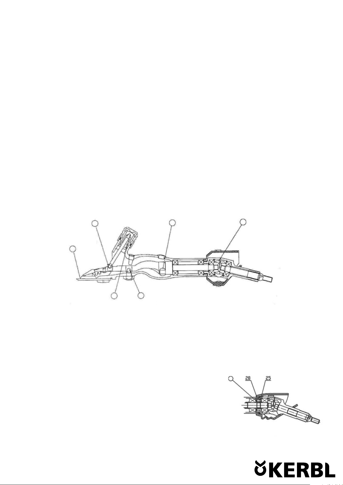
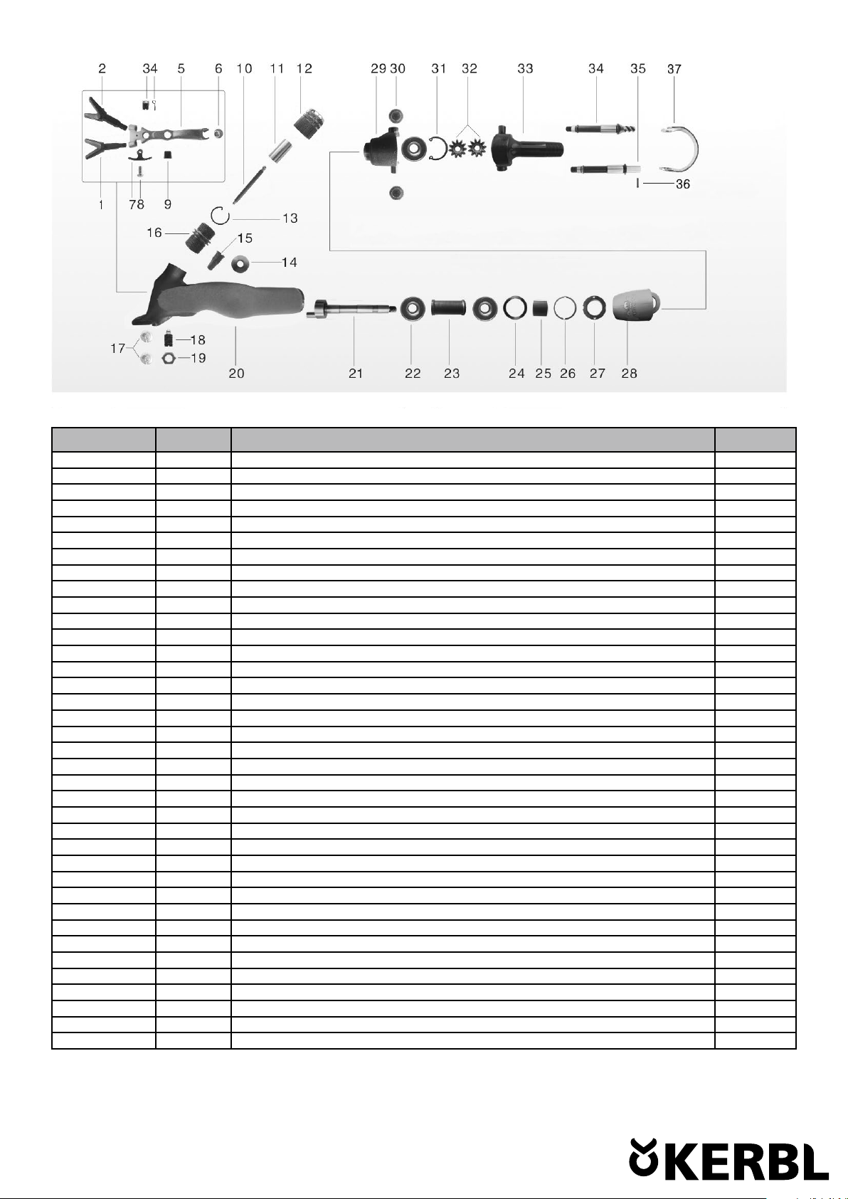
Reguliermutter
Die Reguliermutter (28) kann nach längerem Gebrauch oder bei den ersten Anzeichen von
Verschleiß ersetzt werden. Zum Entfernen der Reguliermutter klopfen, um die beiden Kerben
des Halterings zu lösen. Dann ein Werkzeug in die beiden Löcher der Reguliermutter einfüh-
ren und die Reguliermutter zum Entfernen gegen den Uhrzeigersinn drehen. Dies erfordert
einen gewissen Kraftaufwand, da beim Zusammenbau eine flüssige Schraubensicherung
auf die Reguliermutter aufgebracht wurde. Durch eine neue Reguliermutter samt Haltering
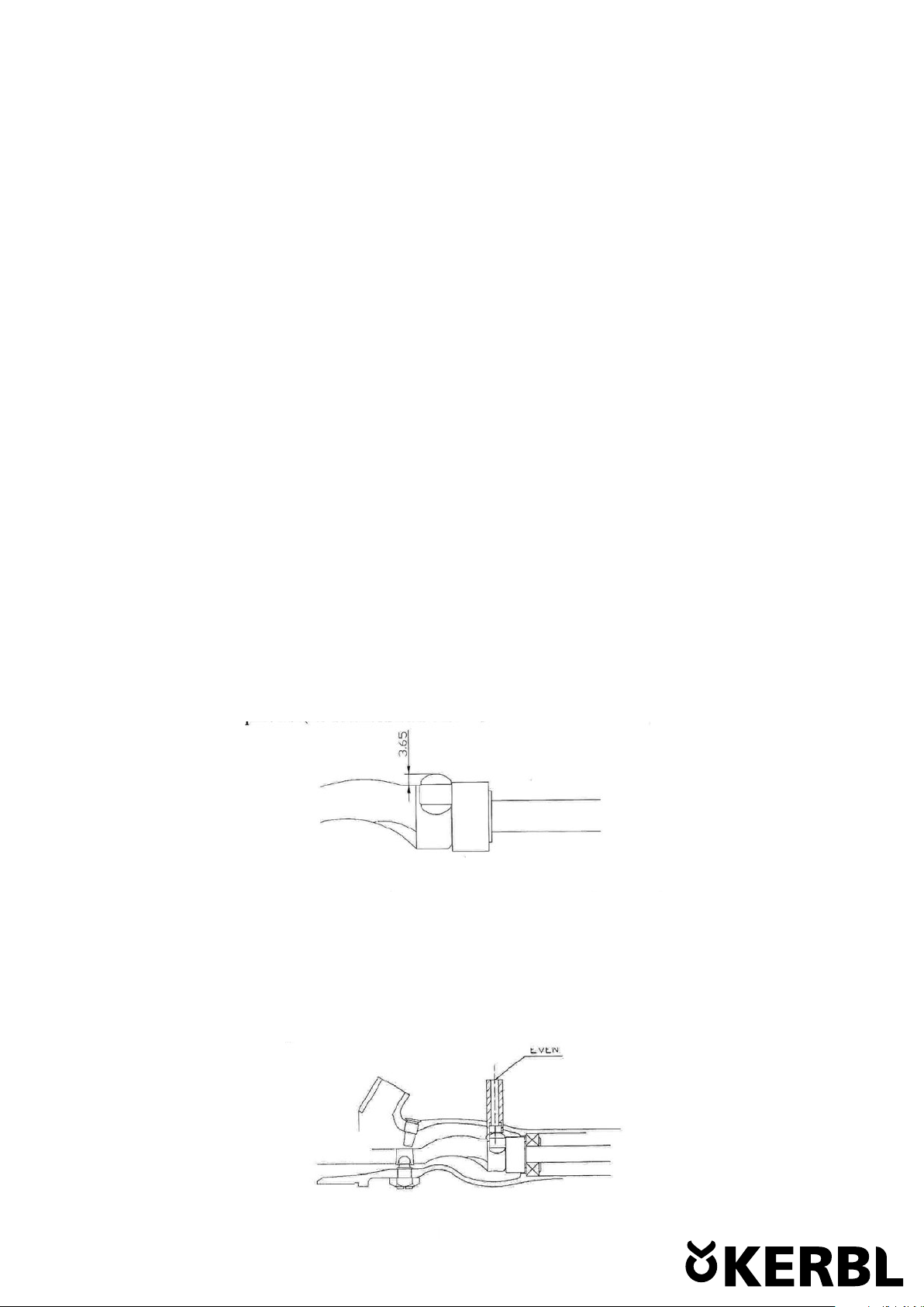
ersetzen, wenn diese verschlissen oder beschädigt sind. Beim Zusammenbauen sollte anae-
rober Kleber auf das Gewinde der Reguliermutter (Abb. 7) aufgebracht werden.
Verschlissene Teile:
Das Handstück sollte nach dem Scheren von 4.000-5.000 Schafen gründlich überprüft werden. Falls Sie Teile finden, die ersetzt
werden müssen, ersetzen Sie diese, denn es spart Kosten und verlängert die Lebensdauer des Handstücks.
Lagerung des Handstücks:
Reinigen Sie am Ende der Saison das Handstück gründlich, überprüfen Sie ihr Gerät und wechseln Sie eventuell abgenutzte Teile aus.
Ölen und Fetten Sie das Handstück ein, wickeln Sie es anschließend in Zeitungspapier, um Feuchtigkeit und Staub fern zu halten.
Bewahren Sie das Gerät an einem trockenen Ort auf, damit es bereit ist für die nächste Saison.
Instandhaltung:
Das Handstück ist ein Präzisionswerkzeug und es ist in der Regel nicht notwendig, die inneren Teile zu zerlegen.
Folgen Sie bitte dieser Anleitung beim Entfernen, Austausch oder Montage des Handstücks bei der routinemäßigen Wartung!
Das Handstück wurde speziell dafür entwickelt, um die Schmierung und Wartung so einfach wie möglich zu gestalten, somit ist die
richtige Instandhaltung sehr entscheidend über die Lebensdauer des Gerätes!
CE-Konformitätserklärung
Hiermit erklärt die Albert KERBL GmbH, dass sich das in dieser Anleitung beschriebene Produkt/Gerät in Übereinstimmung
mit den grundlegenden Anforderungen und den übrigen einschlägigen Bestimmungen der Richtlinien 2006/95/EG,
2004/108/EG und 2006/42/EG befindet. Das CE-Zeichen steht für die Erfüllung der Richt-linien der Europäischen Union.
Die Konformitätserklärung kann unter folgender Internetadresse eingesehen werden: http://www.kerbl.de.
Abb. 7

Albert Kerbl GmbH Felizenzell 9 84428 Buchbach, Germany www.kerbl.de
Positionsnummer Art. Nr. Beschreibung Anzahl
1 BH103 Druckgabel links 1
2 BH104 Druckgabel rechts 1
3 BH107 Gabelkopf, Spitze 1
4 BH108 Bolzenrückholfeder 1
5 BH118 Gabelkörper für Wellington Handstück 1
6 BH120 Exenterrolle 1
7 BH105 Rückholfeder, Gabelbügel 1
8 BHM3X6 Schraube M3 x 6 1
9 BH115 Kugelkopfdeckel 1
10 BH109 Druckstift 1
11 BH112 Druckbüchse 1
12 BH113 Reguliermutter 1
13 BH114 Sicherungsring für Reguliermutter 1
14 BH119 Schmierkappe 1
15 BH111 Sicherungsschraube 1
16 BH110 Drehmuffe 1
17 BH106 Kammplattenschraube (2 St) 1
18 BH116 Kugelkopfschraube 1
19 BH117 Mutter für Kugelkopfschraube 1
20 BH126 Griffstück 1
21 BH321 Exzenterwelle f. 18156 1
22 BH300 Kugellager für Handstück für 18156 1
23 BH324 Buchse lang für Handstück für 18156 1
24 BH122 Federdichtung 1
25 BH325 Buchse kruz für Handstück für 18156 1
26 BH127 Gelenkstückfeder 1
27 BH132 Hülse 1
28 BH331 Abdeckklappe für Handstück für 18156 1
29 BH323 Gelenkstück innen f. Handstück für 18156 1
30 BH134 Federdeckel 1
31 BH137 Seegerring (2St) 1
32 BH128 Zahnrad 2
33 BH129 Gelenkstück außen 1
34 BH130A Antriebswelle, Typ Worm Drive f. Wellington + Blazer Handstü 1
35 BH130B Antriebswelle, Typ Pin Drive f. Wellington + Blazer Handstü 1
36 BH140 Stift für Pin-Anschluss 1
37 BH133 Feder 1

Tondeuse suspendue Wellington 1 vitesse avec poignée Trident Pro
Réf. 18157
Avant de s‘en servir, il est recommandé à tous les utilisateurs de l‘installation fixe pour moutons « Wellington » de lire avec attention
le mode d‘emploi.
Mode d‘emploi
Attention :
• Trois roulements à double rangée de précision sont montés sur la pièce à main et ne peuvent pas être remplacés par des roule-
ments généraux.
• en cas d‘installation d‘un kit de réparation, ne bloquez pas l‘installation fixe pour moutons dans un étau ! Toutes les opérations
doivent être effectuées sur un socle en bois sec et propre ou bien le porte-outil doit être tenu en main pendant l‘opération
• par ailleurs, assurez-vous que le porte-outil soit débrayé avant de desserrer l‘écrou de serrage
• ne démontez jamais le porte-outil sauf pour remplacer une pièce!
• vérifiez si les fourches de pression sont fixées dans les orifices correspondants, sinon la tension nécessaire pourrait ne pas être
obtenue
• assurez-vous que l‘élément articulé est relié au porte-outil si vous utilisez un arbre flexible
Graissage :
Ajoutez de l‘huile toutes les demi-heures !
Versez quelques gouttes d‘une huile de qualité sur la lame supérieure et sur la lame inférieure, sur la pointe de la tête de fourche,
sur les roues dentées et tout autour du galet excentré (à travers l‘orifice de graissage sur la pointe du porte-outil). Desserrez l‘écrou
de serrage et amenez le porte-outil en position verticale, versez ensuite un peu d‘huile dans le capuchon de serrage et soulevez alors
la tête de fourche et versez un peu d‘huile sur la face interne pour lubrifier le couvercle à tête sphérique. (voir Fig. 1)
Lubrification quotidien :
Retirez le capuchon de serrage et appliquez de la graisse généreusement sur la face interne de la douille.
Appliquez également une petite quantité de graisse sur les dents arrière.
Lubrification hebdomadaire :
Retirez les pattes de poulet et lubrifiez généreusement les trous sur le corps de la fourche,
puis remontez les pattes en veillant à ce qu‘elles soient correctement fixées dans les trous.
Retirez les joints de montage en dévissant les rouages, puis appliquez une petite quantité
de graisse dans les interstices annulaires entre le manchon (25) et l‘embout fileté (28).
La graisse doit être de haute qualité et adaptée à l‘utilisation à des températures élevées
jusqu‘à 120 °C. Une lubrification régulière contribue à une longue durée de vie de votre
pièce à main (voir Fig. 2).
Fig. 1
Fig. 2

Pas de graissage pour les paliers :
Les roulements à billes sont intégrés au porte-outil et n‘ont pas besoin d‘être lubrifiés ni graissés.
Attention :
N‘appliquer ni huile ni graisse entre l‘écrou de serrage et le capuchon de serrage, car cela provoquerait une perte de tension !
Choix d‘une lame supérieure et d‘une lame inférieure appropriées
La lame supérieure et la lame inférieure jouent un rôle important lors de la tonte. Par conséquent, il est important de choisir
la lame inférieure adaptée à l‘usage concerné.
Lors du choix de la lame inférieure appropriée, il est important de veiller à la forme, au biseau et à la largeur du peigne (voir Fig. 3).
Dans des conditions de tonte normales :
1. Lame inférieure à biseau court : le biseau court s‘utilise principalement quand la tonte est très facile et que les mou-
tons sont dans les meilleures dispositions pour la tonte
2. Lame inférieure à biseau moyen : le biseau moyen est employé pour la plupart des croisements et convient pour la plu-
part des types de laine.
3. Lame inférieure à biseau long : le biseau long convient en particulier pour les moutons à laine fine et s‘utilise souvent
pour les laines collantes ou pour les tontes précoces
Réglage de la lame supérieure et de la lame inférieure :
Placez une lame supérieure et une lame inférieure sur le porte-outil. Serrez les vis légèrement de façon à pouvoir encore déplacer la
lame inférieure. Assurez-vous que les dents médianes de la lame sont au moins 1,5 à 2,0 mm en avant du porte-outil. Serrez les vis
avec le tournevis fourni. (voir Fig. 4)
Les fourches de pression :
Assurez-vous que chacune des deux fourches de pression peut pivoter librement dans la fourche. Retirez les fourches de pression
une fois par semaine. Nettoyez soigneusement celles-ci ainsi que la face avant de la tête de fourche. Retirez les fourches de pression
à la main ou avec un pince. Appliquez systématiquement une petite quantité de graisse dans les orifices de la fourche quand vous
retirez les « pattes de poulet ». Si le cône et la pointe du côté extérieur des « pattes de poulet » sont usés, il faut les remplacer le plus
tôt possible.
Pression de serrage :
Chaque extrémité de la douille de serrage est de taille différente. L‘extrémité la plus grande va dans la pointe de la tête de fourche
et l‘extrémité la plus petite dans le capuchon de serrage. Pour augmenter la pression sur la lame supérieure et sur la lame inféri-
eure, tournez l‘écrou de serrage Si l‘écrou de serrage est trop serré, le porte-outil, la lame supérieure et la lame inférieure seront en
surchauffe. Ce qui aura pour conséquence que la lame supérieure et la lame inférieure ne couperont pas correctement. Si la machine
ne coupe plus correctement, remplacez la lame supérieure et la lame inférieure par des lames aiguisées. Si la tension n‘est pas su-
sante, songez à remplacer la tige d‘éjection usée, la pointe de la tête de fourche et le capuchon de serrage.
Fig. 3
Fig. 4

Vis :
Le ressort de retenue des fourches de pression est fixé à la tête de fourche par une vis et il ne doit pas être distendu.
Retrait et remplacement de la tête de fourche :
Retirer l‘ensemble du module et le galet excentré
Procédure de démontage :
Il est possible d‘enlever la fourche sans retirer la vis à tête sphérique.
Desserrer d‘abord l‘écrou de serrage, puis retirez la tige d‘éjection et la douille de serrage, ensuite la vis de sécurité située derrière
l‘écrou de serrage et la tête de fourche avec le galet excentré.
Remplacement de la tête de fourche :
Retirez le capuchon de graissage à l‘extrémité du porte-outil. Appliquez une petite quantité de graisse sur le galet excentré (boule)
et la bague de roulement de la tête de fourche. Placez le galet sur la broche à boule (tige) avec une tige, un tournevis ou un objet
ressemblant. Assurez-vous que le côté plat soit tourné vers le cylindre de l‘axe du vilebrequin. Amenez le palier de vilebrequin et le
palier à rouleaux dans la position inférieure du porte-outil.
Faites passer la tête de fourche par le côté avant dans le porte-outil et par le galet. Après avoir vérifié avec soin si le couvercle à tête
sphérique est bien en place sur la vis à tête sphérique, mettez en place la vis de sécurité avant de la bloquer.
Réglage de la vis à tête sphérique :
La vis à tête sphérique a déjà été correctement réglée lors de sa fabrication et elle convient pour n‘importe quelle
épaisseur de lame. S‘il faut la régler à nouveau, utilisez une lame supérieure à moitié usée (env. 3,5 mm)
et une lame inférieure d‘épaisseur quelconque, amenez le galet excentré sur la broche excentrée en position haute
et réglez la vis à tête sphérique selon l‘une des méthodes suivantes :
- Réglage manuel :
Débloquez la vis à tête sphérique, vissez ou dévissez celle-ci pour régler à 3,65 mm l‘écartement entre la face supérieure du galet
et la surface supérieure de la bague de roulement de la tête de fourche. Bloquez à nouveau l‘écrou de la vis à tête sphérique
(voir Fig. 5)
- Réglage à l‘aide du gabarit de réglage :
(Le gabarit de réglage est réalisé spécialement pour le réglage de la vis à tête sphérique). Desserrez les vis et maintenez le gabarit
comme indiqué sur la figure de manière qu‘il forme un angle de 90° avec le porte-outil. Vissez la vis à tête sphérique de manière
que l‘élément central du gabarit soit à la même hauteur que la partie extérieure. Resserrez l‘écrou de la vis à tête sphérique. (Fig. 6)
Fig. 5
Fig. 6

Réglage du circlip de l‘écrou d‘ajustage (écrou de serrage) :
Lors du montage du ressort de rappel dans le manchon rotatif, assurez-vous que la plus grande courbure du ressort soit dans le sens
horaire quand on regarde le porte-outil par le haut. Placez le ressort au-dessus du manchon rotatif et insérez la petite extrémité
courbée dans l‘orifice. Assurez-vous que le ressort soit bien positionné dans la rainure du manchon rotatif.
Attention : l‘absence de ressort de rappel entraîne la perte de tension et peut également provoquer une détérioration du porte-outil !
Retrait des éléments articulés intérieur et extérieur :
Retirez le capuchon de l‘orifice de graissage et insérez un tournevis dans l‘orifice pour fixer la goupille excentrique. Desserrez ensuite
les roues dentées avec une clé plate appropriée. Vous pouvez alors retirer à la main les articulations intérieure et extérieure du manche.
Graissage des couvercles à ressort :
Les couvercles à ressort ne protègent pas seulement de la poussière et des saletés, ils supportent également la plus grande partie du
poids lors du mouvement. Remplacez-les immédiatement quand des traces d‘usure apparaissent. Pour retirer un couvercle à ressort,
glissez un tournevis sous le ressort et enlevez celui-ci de l‘élément articulé en le soulevant. Retirez le couvercle à ressort, graissez-le
et replacez-le ensuite à sa place initiale. Les couvercles à ressort doivent être graissés régulièrement.
Attention : Attention : Assurez-vous que le joint élastique est serré. Remplacez-le immédiatement si ce n‘est pas le cas.
Embout fileté :
L‘embout fileté (28) se remplace après une longue période d‘utilisation ou à l‘apparition
de signes d‘usure. Pour retirer l‘embout fileté, frappez sur les deux encoches de la bague
de retenue pour les retirer. Utilisez ensuite un outil pour maintenir les deux alésages sur
l‘embout fileté, et tournez ce dernier dans le sens anti-horaire pour le retirer. Faites preuve
du force, étant donné que du produit de fixation, comme du Loctite, a été appliqué sur
l‘embout fileté durant le montage. Remplacez par un nouvel embout fileté et une nouvelle
bague de retenue si ces derniers sont usés ou endommagés. Lors du remontage, appliquez
de l‘adhésif anaérobie sur le filetage de l‘embout fileté (ill. 7).
Pièces usées :
Le porte-outil doit faire l‘objet d‘une révision attentive après la tonte de 4 000 à 5 000 moutons. Si vous voyez des pièces à changer,
remplacez-les, cela vous épargnera des dépenses ultérieures et prolongera la durée de vie du porte-outil.
Rangement du porte-outil :
En fin de saison, nettoyez soigneusement le porte-outil, vérifiez l‘appareil et remplacez-les pièces éventuellement usées.
Lubrifiez et graissez le porte-outil, enveloppez-le dans du papier journal pour le protéger de l‘humidité et de la poussière.
Rangez l‘appareil dans un endroit sec afin qu‘il soit prêt pour la prochaine saison.
Maintenance :
Le porte-outil est un outil de précision et, en règle générale, il n‘est pas nécessaire de démonter les pièces internes.
Respectez les indications du présent mode d‘emploi pour toute intervention sur le porte-outil (retrait, remplacement ou montage de
pièces) lors de l‘entretien régulier.
Le porte-outil a été spécialement conçu pour simplifier au maximum le graissage et l‘entretien ; une maintenance correcte est ainsi
déterminante pour la durée de vie de l‘appareil.
Déclaration de conformité CE
La société Albert KERBL GmbH déclare par la présente que le produit/l‘appareil décrit dans le présent mode d‘emploi est en
conformité avec les exigences et autres dispositions applicables des directives 2006/95/CE, 2004/108/CE et 2006/42/CE .
La marque CE atteste que les directives de l‘Union Européenne sont respectées. Vous trouverez la déclaration de conformité sur
le site Internet suivant : http://www.kerbl.de.
Fig. 7

N° d‘ordre N° réf. Description Nombre
1 BH103 fourche de pression gauche 1
2 BH104 fourche de pression droite 1
3 BH107 goupille intérieure 1
4 BH108 resssort de goupille 1
5 BH118 fourche 1
6 BH120 bille 1
7 BH105 ressort de maintien 1
8 BHM3X9 vis panhead 1
9 BH115 goupille d‘oscillateur 1
10 BH109 tige de réglage 1
11 BH112 manchette de réglage 1
12 BH113 douille de réglage 1
13 BH114 ressort de réglage 1
14 BH119 capuchon de graissage 1
15 BH111 vis de sécurité de la fourche 1
16 BH110 manchette filetée 1
17 BH106 vis de peigne (2 unités) 1
18 BH116 vis de centrage 1
19 BH117 contre écrou de la vis de centrage 1
20 BH126 carcasse de poignée 1
21 BH321 villebrequin 1
22 BH600DDU roulement avant 1
23 BH324 douille coulisante longue 1
24 BH122 joint d d ‘étancheité 1
25 BH325 douille coulisante courte 1
26 BH127 ressort de maintien ( villebrequin ) 1
27 BH132 couvre joint 1
28 BH331 garde extérieur 1
29 BH323 joint interne arrière 1
30 BH134 couvercle de joint arrière 1
31 BH137 circlip 1
32 BH128 roues dentées 2
33 BH129 joint externe arrière 1
34 BH130A transmission hélicoidale ( worm drive ) 1
35 BH130B transmission baionette ( pin drive ) 1
36 BH140 broche 1
37 BH133 ressort arrière 1
Albert Kerbl GmbH Felizenzell 9 84428 Buchbach, Germany www.kerbl.com

Stationary Suspended Shearing Machine Wellington 1-speed with handpiece Trident Pro
Art. 18157
All persons carrying out work on or with a Wellington shearing handpiece should read the instruction manual carefully.
Shearing handpiece operating instructions
Caution:
• Three precision double row bearing are fitted to the handpiece and must not be substituted with general bearings.
• When fitting a repair kit to the handpiece never place it in a vice. All work should be carried out on a dry, clean wooden
board or work with the handpiece whilst holding it in your hands.
• Please ensure the handpiece is out of gear before loosening the tensions nut.
• Never disassemble the handpiece unless parts need replacing.
• Check that the chicken feet are secured in the appropriate cutter holes otherwise correct tension cannot be applied.
• Ensure the ferrule is fitted to the handpiece when using a flexible shaft.
Lubrication
Apply oil every half an hour
Place a few drops of clean high-grade oil onto the comb and cutter, tension pin cup, cogs and around the ball (through the oil hole
on the top of the handpiece). Loosen the tension nut and place the handpiece in a vertical position, place some oil into the tension
sleeve, then lift up the fork body and place some oil on the inside to oil the center post cup (Illustration 1).
Grease daily
Remove the tension sleeve and apply a generous amount of grease to the inside of the sleeve. Also apply a small amount of grease
to the rear cogs.
Grease weekly
Remove the chicken feet and place a generous amount of grease into the holes on the
fork body and refit the chicken feet ensuring they are secured in the hole. Take the joints
assembly off by unscrewing cogs, and then apply a small amount of grease into the annu-
lar interspaces between the Bush (25) and the Thread cap (28). The grease must be high
quality and suit for use at temperature up to 120 °C. Regular greasing will be helpful to
the life expectancy of your handpiece (as shown in Fig 2).
No lubrication for bearings
Sealed ball bearings are used in the handpiece and do not need oiling or greasing. The four SF bushes are self-lubricating bearings
and there is no need to oil them. However, adding a little of oil (or grease) occasionally may increase the service life.
Caution: Do not put oil or grease between the tension nut and tension sleeve as this will cause loss of tension.
Illustration 1
Illustration 2

Selecting the appropriate Combs and Cutters
Shearing combs and cutters play a major part in shearing. It is then very important to select the appropriate comb for the job. When
selecting the right comb it is important to consider the shape, bevel and width of the comb (Illustration 3).
Under normal shearing conditions:
1. Short Bevel Comb: The short bevel comb is primarily used when shearing is at its best and the sheep are in top
condition.
2. Medium Bevel Comb: The medium bevel comb is used for the majority of crossbred shearing and is suitable for
most types of wool.
3. Long Bevel Comb: The long bevel comb is particularly suited suited to fine woolled sheep and is used when the
wool is sticky or for early shearing.
Setting a comb and cutter
Place a comb and cutter on the handpiece. Slightly tighten the comb srews until you can just move the comb on the comb bed.
Ensure the centre teeth of the cutter are at least 1.5 to 2.00mm below the scallop of the comb. Tighten up the comb screw driver
provided (Illustration 4).
Pair of the chicken feet
Ensure that each of the chicken feet swivel freely in the fork. Remove the chicken feet once a week. Clean the chicken feet and the
front of the fork body thoroughly. Turn the chicken feet on their side and pull out by hand or by pliers. Always apply a small amount
of grease into the setting holes on the fork body when replacing the chicken feet. When the cone and tip on the outer half of the
chicken feet is worn out, it must be replaced as soon as possible.
Tension pressure
Each end of the tension pin is different in size. Ensure the larger end fits into the tension pin cup and the smaller end into the ten-
sion pin sleeve. Increase the pressure on the comb and cutter by turning the tension nut. If the tension nut is tightened excessively
the handpiece body and combs and cutters will overheat very quickly. This will also cause the comb and cutter to not cut correctly. If
the handpiece is not cutting then replace the comb and cutter with a freshly ground comb and cutter. If adequate tension cannot be
applied then consider replacing the worn tension pin, tension pin cup and tension sleeve.
Screw
The chicken feet retaining spring is fixed to the fork body by a screw and must not be loose.
Remove and replace the fork body assembly and the roller
Method of removal:
The fork body assembly can be removed without removing the center post. First unscrew the tension nut, then remove the tension
pin and tension sleeve. Remove the safety screw behind the tension nut and remove the fork body with the roller attached.
Illustration 3
Illustration 4

Replacing fork body:
Remove the oil hole cap on the top of the handpiece. Place a small amount of grease onto the roller (ball) and ball race of the fork
body. Place the ball onto the crankshaft (pin) using a pen, screwdriver or other suitable method (Make sure that the flat side of the
roller is facing the crank spindle). Place the crank and roller in the bottom position in the handpiece.
Insert the fork body from the front of the handpiece and over the ball. After it´s confirmed that the center post cup is sitting onto
center post correctly, replace and tighten the safety screw.
Adjusting the center post
The center post has been set in the correct position in the factory and is suitable for any thickness cutter. If it need to be adjusted,
use a half worn cutter (approx 3.5mm) and any thickness comb, Rotate the roller on the crank spindle to the uppermost position and
adjust the center post by either of the following methods.
• Adjusting by hand:
Loosen the center post nut and screw the center post in or out to set the distance from the top of roller to the upper surface of the
ball race on the fork body to 3.65mm. Retighten the center post nut (As shown in illustration 5).
• Adjusting using the post gauge: 8the post gauge is designed specifically to adjust the level of the center post
Loosen the screws and insert the post gauge as per illustration, keeping it at 90 degrees to the handpiece. Turn the center post
until the center of the gauge is level with the gauge top. Retighten the center post nut (Illustration 6).
Setting the tension retaining ring
When fitting the tension retaining spring into the threaded bush, make sure the large curve of the spring faces directly in a clockwise
direction when looking down on the handpiece. Place the spring over the threaded bush and insert the small curved end into the
hole. Ensure the spring is seated properly in the groove of threaded bush.
Caution:
Absence of the tension retaining spring will contribute to loss of tension and could damage the handpiece.
Removing the inner and outer joints
Remove the oil hole cap and place a screwdriver through the hole to stop the crank spindle from turning. Loosen the cogs using
a suitable cog spanner. You can then remove the inner and outer joint from the handle by hand.
Lubricating the back joint caps
The back joint caps, not only keep the dirt and dust out, but also bear most of the weight of the backend movement. Replace if
showing signs of wear. To remove the back joint cap place a screwdriver under the back joint spring and pries it away from the joint.
Remove the joint cap, re-grease and put it back in place. The back joint should be greased periodically.
Illustration 5
Illustration 6

Caution: Ensure the joint spring is not loose, replacing immediately if it is loose.
Thread Cap
The thread cap (28) is replaceable after along usage time or when sign of wear appears.
To remove the thread cap tap to remove the two notch on the retaining ring. Then use a tool
to hold the two holes on the thread cap, turn the thread cap anti-clockwise to remove.
Will need some leverage as Loctite was used on the thread cap during assembly. Replace with
new thread cap and retaining ring if they are worn or damaged. When re-assembling anaero-
bic adhesive should be applied onto the thread of the thread cap (Fig 7).
Worn party
The handpiece should be checked thoroughly after shearing 4000 – 5000 sheep. Any party found to be worn should be re-placed as
this will save costs and enhance the life expectancy of the handpiece.
Handpiece storage
At the end of the season the handpiece should be thoroughly cleaned, examined and any parts found to be worn should be
replaced. Completely grease and oil the handpiece and wrap in newspaper to keep moisture and dust out. Store in a dry place
ready for the next season.
Maintenance
The handpiece is a precision tool and is generally not necessary to disassemble the inner rotating party.
Please follow this instruction when removing, replacing or assembling the handpiece during routine maintenance. The handpiece is
designed to allow easy lubrication and maintenance, so the proper way of lubrication and maintenance is very important to enhance
the life expectancy of the handpiece.
Additional instruction for 18155 Handpiece
As there have been some significant improvements on the 1C model, now you have got the 2C model in hand.
Hereby we would like to draw your attention to the difference between the 1C and 2C model handpiece.
According to the drawing inside the bottom page, the 2C model will not have these parts any more:
27. SF-1 bush; 35. Washer(1); 40.Middle SF bush; 41.Small SF bush(2)
26. Retaining clip has become into retaining ring.
Grease weekly: You need to take the joints assembly off by unscrewing cogs, and then apply a generous amount
of grease into the annular interspaces between the Bush(25) and Thread cap (28).
The grease must be high quality and suit for use at temperature up to 120°.
To keep doing this will be much helpful to the life expectancy of your handpiece.
The thread cap (28) is replaceable after long time using or wearing out. When it re-assembles back, the Loctite-222 (anaerobic
adhesive) should be applied onto the thread.
Declaration of Conformity
Albert KERBL GmbH hereby declares that the product / device described in these instructions complies with the fundamen-
tal requirements and other relevant stipulations of Directives 2006/95/EU, 2004/108/EU and 2006/42/EU . The CE mark
confirms compliance with the Directives of the European Union. The declaration of conformity can be viewed by visiting the following
website: http://www.kerbl.com.
Illustration 7

item number ref. no. description quantity
1 BH103 Chickenfeet left 1
2 BH104 Chickenfeet right 1
3 BH107 Tension pin cup 1
4 BH108 Tension pin spring 1
5 BH118 Fork body 1
6 BH120 Roller 1
7 BH105 Retaining spring 1
8 BHM3X6 Cross recess head screw M3 x 6 1
9 BH115 Center post cup 1
10 BH109 Tension pin 1
11 BH112 Tension sleeve 1
12 BH113 Tension nut 1
13 BH114 Tension retaining ring 1
14 BH119 Cover cap 1
15 BH111 Safety screw 1
16 BH110 Thread bush 1
17 BH106 Comb screw 1
18 BH116 Center post 1
19 BH117 Center post nut 1
20 BH126 Handle 1
21 BH321 Crank spindle 1
22 BH300 Ball bearing 1
23 BH324 Long bush 1
24 BH122 Spring washer 1
25 BH325 Short bush 1
26 BH127 Retaining ring 1
27 BH132 Thread cap 1
28 BH331 Joing guard 1
29 BH323 Inner joint 1
30 BH134 Joint cap 1
31 BH137 Joint circlip (2 x) 1
32 BH128 Cog 2
33 BH129 Outer joint 1
34 BH130A Worm drive 1
35 BH130B Pin drive 1
36 BH140 Pin 1
37 BH133 Joint spring 1
Albert Kerbl GmbH Felizenzell 9 84428 Buchbach, Germany www.kerbl.com

This manual suits for next models
2
Table of contents
Languages:
Other Kerbl Power Tools manuals
Popular Power Tools manuals by other brands

Hi-Force
Hi-Force TWS-N Series Operating instructions manual

STEINEL
STEINEL HL 1620 S operating instructions

Hercules
Hercules HE41 Owner's manual & safety instructions

Drill Master
Drill Master 68986 owner's manual

Parkside
Parkside POF 1200 C2 Translation of the original instructions

Inncen
Inncen Feilo 01A user manual