Bordignon DTAP 1 User manual

Where innovation happenswww.bordignon.com
4.0 Direct Drive tapping unit
with touch screen
multiple control panel
INSTRUCTIONS MANUAL


Direct Drive tapping unit with touch screen multiple control panel
ATTENTION!
BEFORE connecting the tapping unit, read this instruction manual very carefully,
especially the warnings on page 1
Rev. 05

Direct Drive tapping unit with touch screen multiple control panel
Index
WARNINGS ............................................................................................................................................................................................... 1
INTRODUCTION ..................................................................................................................................................................................... 2
CONTROL PANEL ................................................................................................................................................................................... 2
TAPPING UNIT ........................................................................................................................................................................................ 3
FUNCTIONING ........................................................................................................................................................................................ 3
INSTALLING ............................................................................................................................................................................................. 4
ACCESSING FUNCTIONS WITH A PASSWORD ............................................................................................................................ 4
SET UP ....................................................................................................................................................................................................... 5
TORQUE CONTROL ................................................................................................................................................................................ 5
THREADING TIME .................................................................................................................................................................................. 6
LUBRICATION .......................................................................................................................................................................................... 6
TAP CHANGE ............................................................................................................................................................................................ 7
ALARMS .................................................................................................................................................................................................... 7
TROUBLE SHOOTING ........................................................................................................................................................................... 8
SERVICE
— Reverse cycle ................................................................................................................................................................................... 10
— Tap data ............................................................................................................................................................................................. 10
— Counter .............................................................................................................................................................................................. 10
— Setting a production lot ............................................................................................................................................................... 11
— Lubrication oil .................................................................................................................................................................................. 11
— Programs ........................................................................................................................................................................................... 11
— Diagnostic ......................................................................................................................................................................................... 12
— Alarms history ................................................................................................................................................................................. 12
— Language selection ........................................................................................................................................................................ 12
— Brightness control ......................................................................................................................................................................... 12
CHANGE SUPER USER PASSWORD ................................................................................................................................................ 12
DISPOSAL OF COMPONENTS AND MATERIAL ........................................................................................................................... 13
OPTIONAL
— D-TC: tapping control sensor ...................................................................................................................................................... 14
— D-USB: USB drive for data reading ........................................................................................................................................... 15
— D-APR: automatic pressure regulator...................................................................................................................................... 17
— Right/left hand threading ........................................................................................................................................................... 18
— Change of return speed ................................................................................................................................................................ 19
4.0 Functions and configuration .................................................................................................................................................. 20
4.0 Log converter ............................................................................................................................................................................... 22
4.0 OPC-UA viewer ............................................................................................................................................................................. 23
4.0 OPC-UA global variables ......................................................................................................................................................... 24
DTAP-1 DRAWING ............................................................................................................................................................................... 26
DTAP-2 DRAWING .............................................................................................................................................................................. 27
DTAP-3 DRAWING .............................................................................................................................................................................. 28
CONTROL PANEL DRAWING ............................................................................................................................................................ 29
PREHOLES ............................................................................................................................................................................................. 30
CE DECLARATION OF CONFORMITY ............................................................................................................................................. 31
ELECTRIC DIAGRAM ........................................................................................................................................................................... 32
1
Direct Drive tapping unit with touch screen multiple control panel
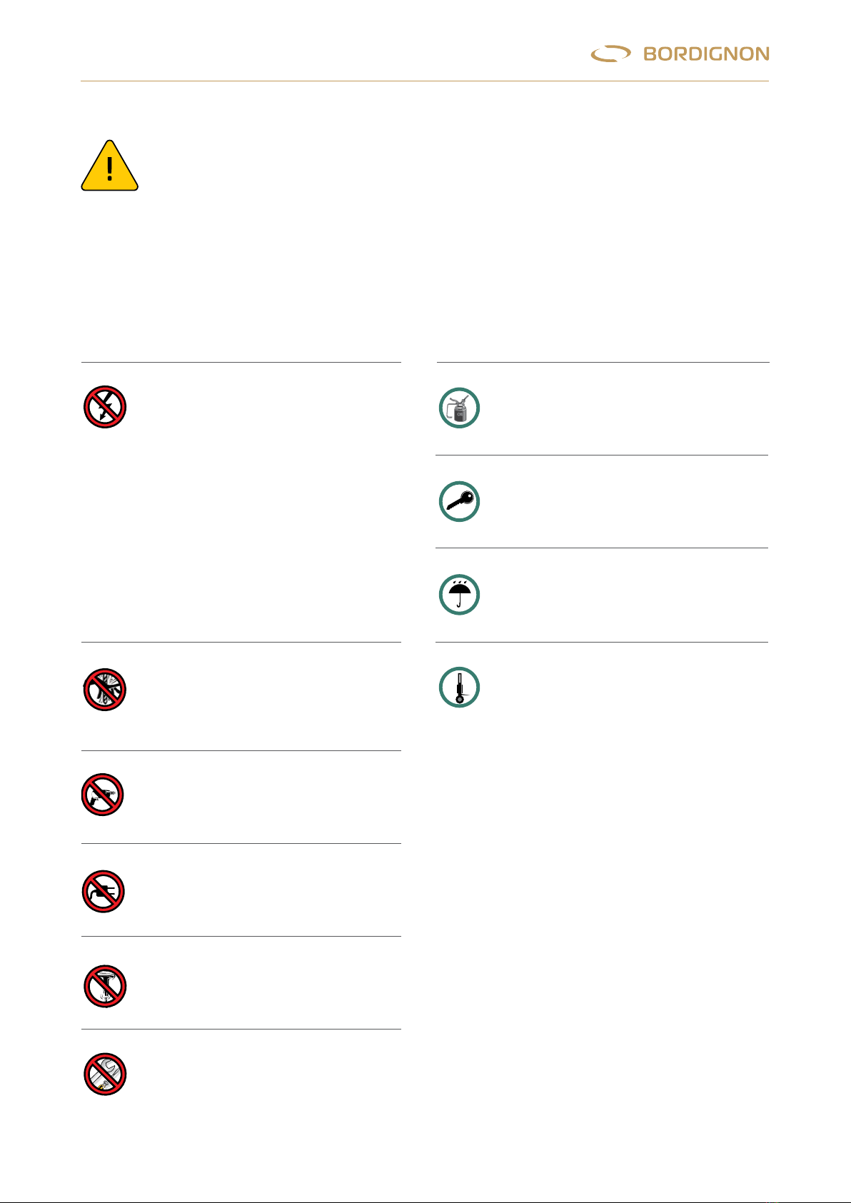
WARNINGS
NO YES
Max.80°C
AVVERTENZE
1
NONESEGUIRELAVORAZIONIMECCANICHESULLA MASCHIATRICEOSUL PANNELLO
NON ALLACCIARE ALTRE APPARECCHIATURE AL PANNELLO
LAVORARECONIL PANNELLOSEMPRECHIUSO
PROTEGGEREIL PANNELLOEDIL MOTOREDA LIQUIDI,POLVERIE TRUCIOLI
TEMPERATURA MASSIMA DILAVORO80°
MASCHIARESEMPRECONLUBRIFICANTE
-
NONSCOLLEGARE/COLLEGAREICAVIMENTRELA JOLLY TAP EINFUNZIONEO
E’ CONNESSA ALLA LINEA ELETTRICA
-MAIMODIFICAREIL PANNELLODICONTROLLOELETTRICOE/OLA MASCHIATRICE
- NONSMONTARENE’ TOCCARELA MASCHIATRICE,NON AVVICINARSI ALLA MASCHIATRICE
QUANDOE’ COLLEGATA ALLA LINEA ELETTRICA (ECCETTODURANTEIL CAMBIOMASCHIO)
-NONCOLLEGAREPANNELLOEMASCHIATRICECONNUMERODISERIEDIVERSO
(vedi “INSTALLAZIONE” -pag.4)
NONFISSAREIL PANNELLO A SUPERFICIVIBRANTI
MANUTENZIONESOLODA PERSONALE AUTORIZZATO
TOGLIERELA TENSIONEOPREMEREIL TASTOEMERGENZA PRIMA DI TOCCAREL’UTENSILE.
ALLONTANARSIDALL’ UTENSILEINROTAZIONE
Always use lubricant in threading process
Max.80°C
AVVERTENZE
1
NONESEGUIRELAVORAZIONIMECCANICHESULLA MASCHIATRICEOSUL PANNELLO
NON ALLACCIARE ALTRE APPARECCHIATURE AL PANNELLO
LAVORARECONIL PANNELLOSEMPRECHIUSO
PROTEGGEREIL PANNELLOEDIL MOTOREDA LIQUIDI,POLVERIE TRUCIOLI
TEMPERATURA MASSIMA DILAVORO80°
MASCHIARESEMPRECONLUBRIFICANTE
-
NONSCOLLEGARE/COLLEGAREICAVIMENTRELA JOLLY TAP EINFUNZIONEO
E’ CONNESSA ALLA LINEA ELETTRICA
-MAIMODIFICAREIL PANNELLODICONTROLLOELETTRICOE/OLA MASCHIATRICE
- NONSMONTARENE’ TOCCARELA MASCHIATRICE,NON AVVICINARSI ALLA MASCHIATRICE
QUANDOE’ COLLEGATA ALLA LINEA ELETTRICA (ECCETTODURANTEIL CAMBIOMASCHIO)
-NONCOLLEGAREPANNELLOEMASCHIATRICECONNUMERODISERIEDIVERSO
(vedi “INSTALLAZIONE” -pag.4)
NONFISSAREIL PANNELLO A SUPERFICIVIBRANTI
MANUTENZIONESOLODA PERSONALE AUTORIZZATO
TOGLIERELA TENSIONEOPREMEREIL TASTOEMERGENZA PRIMA DI TOCCAREL’UTENSILE.
ALLONTANARSIDALL’ UTENSILEINROTAZIONE
The panel must always be closed when
working
Max.80°C
AVVERTENZE
1
NONESEGUIRELAVORAZIONIMECCANICHESULLA MASCHIATRICEOSUL PANNELLO
NON ALLACCIARE ALTRE APPARECCHIATURE AL PANNELLO
LAVORARECONIL PANNELLOSEMPRECHIUSO
PROTEGGEREIL PANNELLOEDIL MOTOREDA LIQUIDI,POLVERIE TRUCIOLI
TEMPERATURA MASSIMA DILAVORO80°
MASCHIARESEMPRECONLUBRIFICANTE
-
NONSCOLLEGARE/COLLEGAREICAVIMENTRELA JOLLY TAP EINFUNZIONEO
E’ CONNESSA ALLA LINEA ELETTRICA
-MAIMODIFICAREIL PANNELLODICONTROLLOELETTRICOE/OLA MASCHIATRICE
- NONSMONTARENE’ TOCCARELA MASCHIATRICE,NON AVVICINARSI ALLA MASCHIATRICE
QUANDOE’ COLLEGATA ALLA LINEA ELETTRICA (ECCETTODURANTEIL CAMBIOMASCHIO)
-NONCOLLEGAREPANNELLOEMASCHIATRICECONNUMERODISERIEDIVERSO
(vedi “INSTALLAZIONE” -pag.4)
NONFISSAREIL PANNELLO A SUPERFICIVIBRANTI
MANUTENZIONESOLODA PERSONALE AUTORIZZATO
TOGLIERELA TENSIONEOPREMEREIL TASTOEMERGENZA PRIMA DI TOCCAREL’UTENSILE.
ALLONTANARSIDALL’ UTENSILEINROTAZIONE
Protect the panel and the motor from
liquids, dust and shavings
Max.80°C
AVVERTENZE
1
NONESEGUIRELAVORAZIONIMECCANICHESULLA MASCHIATRICEOSUL PANNELLO
NON ALLACCIARE ALTRE APPARECCHIATURE AL PANNELLO
LAVORARECONIL PANNELLOSEMPRECHIUSO
PROTEGGEREIL PANNELLOEDIL MOTOREDA LIQUIDI,POLVERIE TRUCIOLI
TEMPERATURA MASSIMA DILAVORO80°
MASCHIARESEMPRECONLUBRIFICANTE
-
NONSCOLLEGARE/COLLEGAREICAVIMENTRELA JOLLY TAP EINFUNZIONEO
E’ CONNESSA ALLA LINEA ELETTRICA
-MAIMODIFICAREIL PANNELLODICONTROLLOELETTRICOE/OLA MASCHIATRICE
- NONSMONTARENE’ TOCCARELA MASCHIATRICE,NON AVVICINARSI ALLA MASCHIATRICE
QUANDOE’ COLLEGATA ALLA LINEA ELETTRICA (ECCETTODURANTEIL CAMBIOMASCHIO)
-NONCOLLEGAREPANNELLOEMASCHIATRICECONNUMERODISERIEDIVERSO
(vedi “INSTALLAZIONE” -pag.4)
NONFISSAREIL PANNELLO A SUPERFICIVIBRANTI
MANUTENZIONESOLODA PERSONALE AUTORIZZATO
TOGLIERELA TENSIONEOPREMEREIL TASTOEMERGENZA PRIMA DI TOCCAREL’UTENSILE.
ALLONTANARSIDALL’ UTENSILEINROTAZIONE
Max. operating temperature 80°
— Do not disconnect or connect the
cables when the tapping unit is
working or it is connected to power
supply
— Never make changes to the panel or
tapping unit
— Do not disassemble the tapping unit,
never touch or stand near to the
tapping unit when it is connected
to power supply (except during tap
changing operation)
— Do not connect a panel to a tapping
unit with different serial nr. (see page
4 “installing”)
Max.80°C
AVVERTENZE
1
NONESEGUIRELAVORAZIONIMECCANICHESULLA MASCHIATRICEOSUL PANNELLO
NON ALLACCIARE ALTRE APPARECCHIATURE AL PANNELLO
LAVORARECONIL PANNELLOSEMPRECHIUSO
PROTEGGEREIL PANNELLOEDIL MOTOREDA LIQUIDI,POLVERIE TRUCIOLI
TEMPERATURA MASSIMA DILAVORO80°
MASCHIARESEMPRECONLUBRIFICANTE
-NONSCOLLEGARE/COLLEGAREICAVIMENTRELA JOLLY TAP EINFUNZIONEO
E’ CONNESSA ALLA LINEA ELETTRICA
-MAIMODIFICAREIL PANNELLODICONTROLLOELETTRICOE/OLA MASCHIATRICE
- NONSMONTARENE’ TOCCARELA MASCHIATRICE,NON AVVICINARSI ALLA MASCHIATRICE
QUANDOE’ COLLEGATA ALLA LINEA ELETTRICA (ECCETTODURANTEIL CAMBIOMASCHIO)
-NONCOLLEGAREPANNELLOEMASCHIATRICECONNUMERODISERIEDIVERSO
(vedi “INSTALLAZIONE” -pag.4)
NONFISSAREIL PANNELLO A SUPERFICIVIBRANTI
MANUTENZIONESOLODA PERSONALE AUTORIZZATO
TOGLIERELA TENSIONEOPREMEREIL TASTOEMERGENZA PRIMA DI TOCCAREL’UTENSILE.
ALLONTANARSIDALL’ UTENSILEINROTAZIONE
Unplug the machine or press the
emergency button before touching it.
Never approach the device while it is
rotating
Max.80°C
AVVERTENZE
1
NONESEGUIRELAVORAZIONIMECCANICHESULLA MASCHIATRICEOSUL PANNELLO
NON ALLACCIARE ALTRE APPARECCHIATURE AL PANNELLO
LAVORARECONIL PANNELLOSEMPRECHIUSO
PROTEGGEREIL PANNELLOEDIL MOTOREDA LIQUIDI,POLVERIE TRUCIOLI
TEMPERATURA MASSIMA DILAVORO80°
MASCHIARESEMPRECONLUBRIFICANTE
-NONSCOLLEGARE/COLLEGAREICAVIMENTRELA JOLLY TAP EINFUNZIONEO
E’ CONNESSA ALLA LINEA ELETTRICA
-MAIMODIFICAREIL PANNELLODICONTROLLOELETTRICOE/OLA MASCHIATRICE
- NONSMONTARENE’ TOCCARELA MASCHIATRICE,NON AVVICINARSI ALLA MASCHIATRICE
QUANDOE’ COLLEGATA ALLA LINEA ELETTRICA (ECCETTODURANTEIL CAMBIOMASCHIO)
-NONCOLLEGAREPANNELLOEMASCHIATRICECONNUMERODISERIEDIVERSO
(vedi “INSTALLAZIONE” -pag.4)
NONFISSAREIL PANNELLO A SUPERFICIVIBRANTI
MANUTENZIONESOLODA PERSONALE AUTORIZZATO
TOGLIERELA TENSIONEOPREMEREIL TASTOEMERGENZA PRIMA DI TOCCAREL’UTENSILE.
ALLONTANARSIDALL’ UTENSILEINROTAZIONE
Do not perform mechanical work on the
tapping unit or panel
Max.80°C
AVVERTENZE
1
NONESEGUIRELAVORAZIONIMECCANICHESULLA MASCHIATRICEOSUL PANNELLO
NON ALLACCIARE ALTRE APPARECCHIATURE AL PANNELLO
LAVORARECONIL PANNELLOSEMPRECHIUSO
PROTEGGEREIL PANNELLOEDIL MOTOREDA LIQUIDI,POLVERIE TRUCIOLI
TEMPERATURA MASSIMA DILAVORO80°
MASCHIARESEMPRECONLUBRIFICANTE
-NONSCOLLEGARE/COLLEGAREICAVIMENTRELA JOLLY TAP EINFUNZIONEO
E’ CONNESSA ALLA LINEA ELETTRICA
-MAIMODIFICAREIL PANNELLODICONTROLLOELETTRICOE/OLA MASCHIATRICE
- NONSMONTARENE’ TOCCARELA MASCHIATRICE,NON AVVICINARSI ALLA MASCHIATRICE
QUANDOE’ COLLEGATA ALLA LINEA ELETTRICA (ECCETTODURANTEIL CAMBIOMASCHIO)
-NONCOLLEGAREPANNELLOEMASCHIATRICECONNUMERODISERIEDIVERSO
(vedi “INSTALLAZIONE” -pag.4)
NONFISSAREIL PANNELLO A SUPERFICIVIBRANTI
MANUTENZIONESOLODA PERSONALE AUTORIZZATO
TOGLIERELA TENSIONEOPREMEREIL TASTOEMERGENZA PRIMA DI TOCCAREL’UTENSILE.
ALLONTANARSIDALL’ UTENSILEINROTAZIONE
Do not connect other equipment to the
panel
Max.80°C
AVVERTENZE
1
NONESEGUIRELAVORAZIONIMECCANICHESULLA MASCHIATRICEOSUL PANNELLO
NON ALLACCIARE ALTRE APPARECCHIATURE AL PANNELLO
LAVORARECONIL PANNELLOSEMPRECHIUSO
PROTEGGEREIL PANNELLOEDIL MOTOREDA LIQUIDI,POLVERIE TRUCIOLI
TEMPERATURA MASSIMA DILAVORO80°
MASCHIARESEMPRECONLUBRIFICANTE
-NONSCOLLEGARE/COLLEGAREICAVIMENTRELA JOLLY TAP EINFUNZIONEO
E’ CONNESSA ALLA LINEA ELETTRICA
-MAIMODIFICAREIL PANNELLODICONTROLLOELETTRICOE/OLA MASCHIATRICE
- NONSMONTARENE’ TOCCARELA MASCHIATRICE,NON AVVICINARSI ALLA MASCHIATRICE
QUANDOE’ COLLEGATA ALLA LINEA ELETTRICA (ECCETTODURANTEIL CAMBIOMASCHIO)
-NONCOLLEGAREPANNELLOEMASCHIATRICECONNUMERODISERIEDIVERSO
(vedi “INSTALLAZIONE” -pag.4)
NONFISSAREIL PANNELLO A SUPERFICIVIBRANTI
MANUTENZIONESOLODA PERSONALE AUTORIZZATO
TOGLIERELA TENSIONEOPREMEREIL TASTOEMERGENZA PRIMA DI TOCCAREL’UTENSILE.
ALLONTANARSIDALL’ UTENSILEINROTAZIONE
Do not place the panel on vibrating
surfaces
Max.80°C
AVVERTENZE
1
NONESEGUIRELAVORAZIONIMECCANICHESULLA MASCHIATRICEOSUL PANNELLO
NON ALLACCIARE ALTRE APPARECCHIATURE AL PANNELLO
LAVORARECONIL PANNELLOSEMPRECHIUSO
PROTEGGEREIL PANNELLOEDIL MOTOREDA LIQUIDI,POLVERIE TRUCIOLI
TEMPERATURA MASSIMA DILAVORO80°
MASCHIARESEMPRECONLUBRIFICANTE
-NONSCOLLEGARE/COLLEGAREICAVIMENTRELA JOLLY TAP EINFUNZIONEO
E’ CONNESSA ALLA LINEA ELETTRICA
-MAIMODIFICAREIL PANNELLODICONTROLLOELETTRICOE/OLA MASCHIATRICE
- NONSMONTARENE’ TOCCARELA MASCHIATRICE,NON AVVICINARSI ALLA MASCHIATRICE
QUANDOE’ COLLEGATA ALLA LINEA ELETTRICA (ECCETTODURANTEIL CAMBIOMASCHIO)
-NONCOLLEGAREPANNELLOEMASCHIATRICECONNUMERODISERIEDIVERSO
(vedi “INSTALLAZIONE” -pag.4)
NONFISSAREIL PANNELLO A SUPERFICIVIBRANTI
MANUTENZIONESOLODA PERSONALE AUTORIZZATO
TOGLIERELA TENSIONEOPREMEREIL TASTOEMERGENZA PRIMA DI TOCCAREL’UTENSILE.
ALLONTANARSIDALL’ UTENSILEINROTAZIONE
Maintenance must be performed only by
authorized staff
This manual suits for next models
2
Table of contents
Other Bordignon Industrial Equipment manuals


