Silca Rekord AY User manual

D434249XA vers.4.0
Operating manual
Translation of the original instructions

© 2008 SILCA S.p.A - Vittorio Veneto
This manual has been drawn up by SILCA S.p.A.
All rights reserved. No part of this publication may be reproduced or used in any form orby any means (photocopying,
microfilm or other) without the written permission of SILCA S.p.A.
Edition: February 2019
Printed in Vittorio Veneto
by SILCA S.p.A.
via Podgora, 20 (Z.I.)
31029 VITTORIO VENETO (TV) - Italy
IMPORTANT NOTE: in compliance with current regulations relating to industrial property, we hereby state that the
trade-marks or trade names mentioned in our documentation are the exclusive property of authorized
manufacturers of locks and users.
Said trade-marks or trade names are nominated only for the purposes of information so that any lock for which our
keys are made can be rapidly identified.

INDEX
1 TRANSPORT ...................................................................................................5
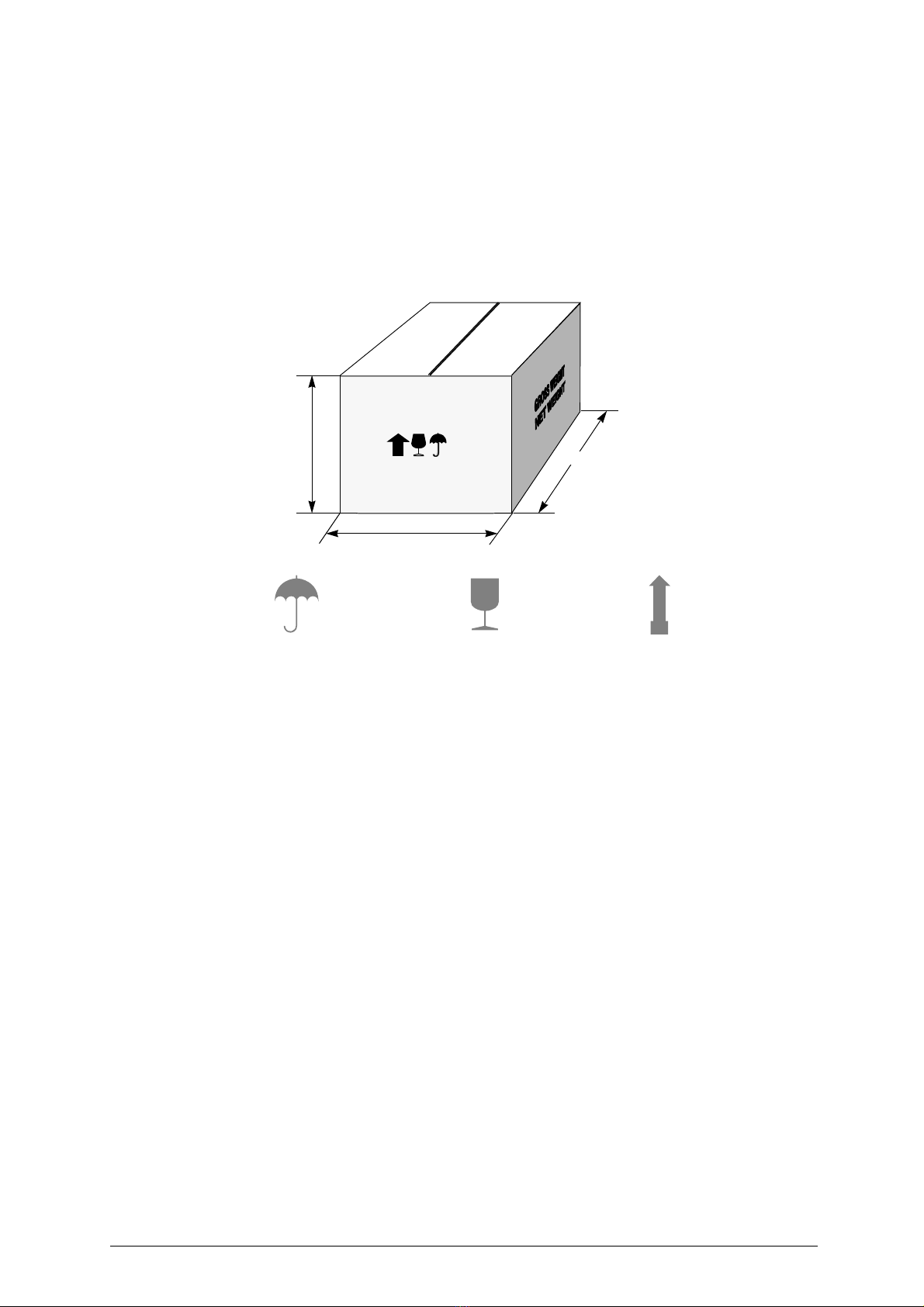
1.1 Packing .................................................................................................5
1.2 Transport ..............................................................................................5
1.3 Unpacking .............................................................................................5
1.4 Handling the machine ...........................................................................5
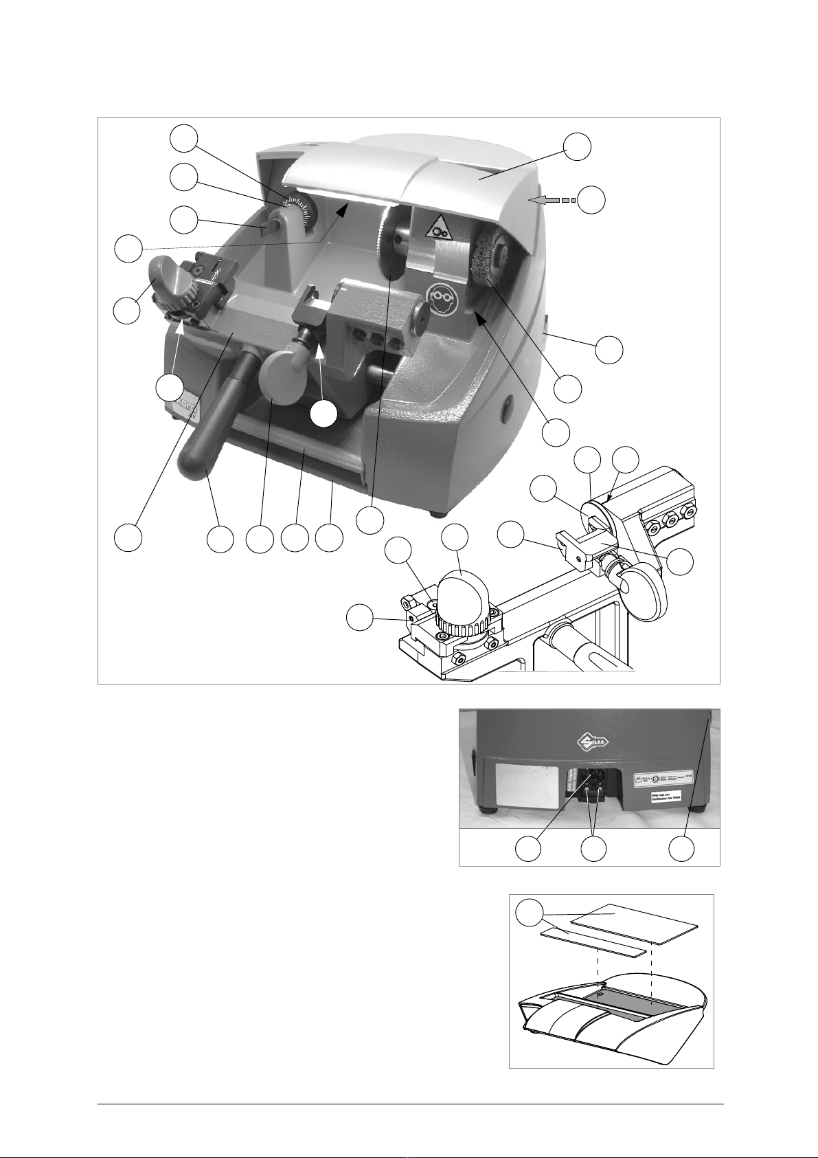
2 WORKING PARTS ..........................................................................................6
3 MACHINE DESCRIPTION ...............................................................................7
3.1 Further Risks ........................................................................................8
3.2 Technical Data ......................................................................................8
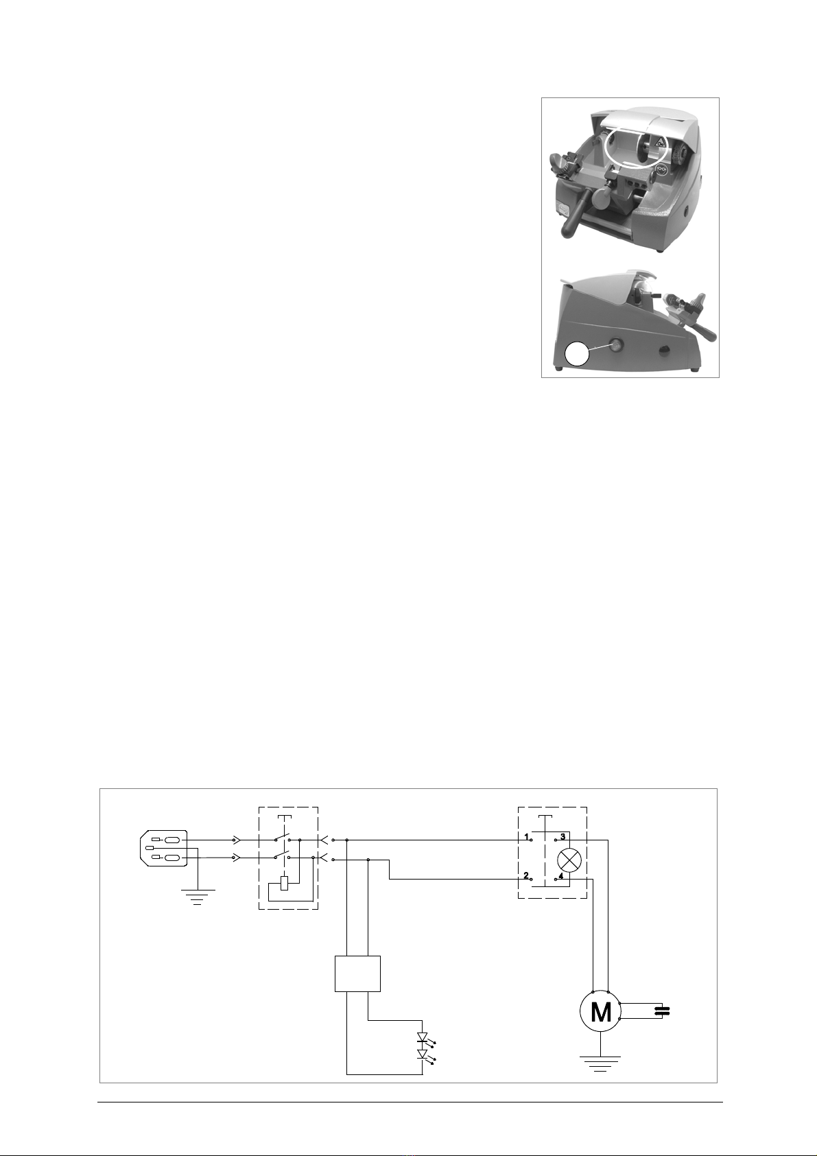
3.3 Electric circuit .......................................................................................8
4 ACCESSORIES PROVIDED ...........................................................................9
5 MACHINE INSTALLATION and PREPARATION ........................................10
5.1 Checking for damage .........................................................................10
5.2 Environmental conditions ...................................................................10
5.3 Removing the blocks ..........................................................................10
5.4 Positioning ..........................................................................................10
5.5 Separate parts ....................................................................................11
5.6 Description of work station .................................................................11
5.7 Connection to the mains .....................................................................12
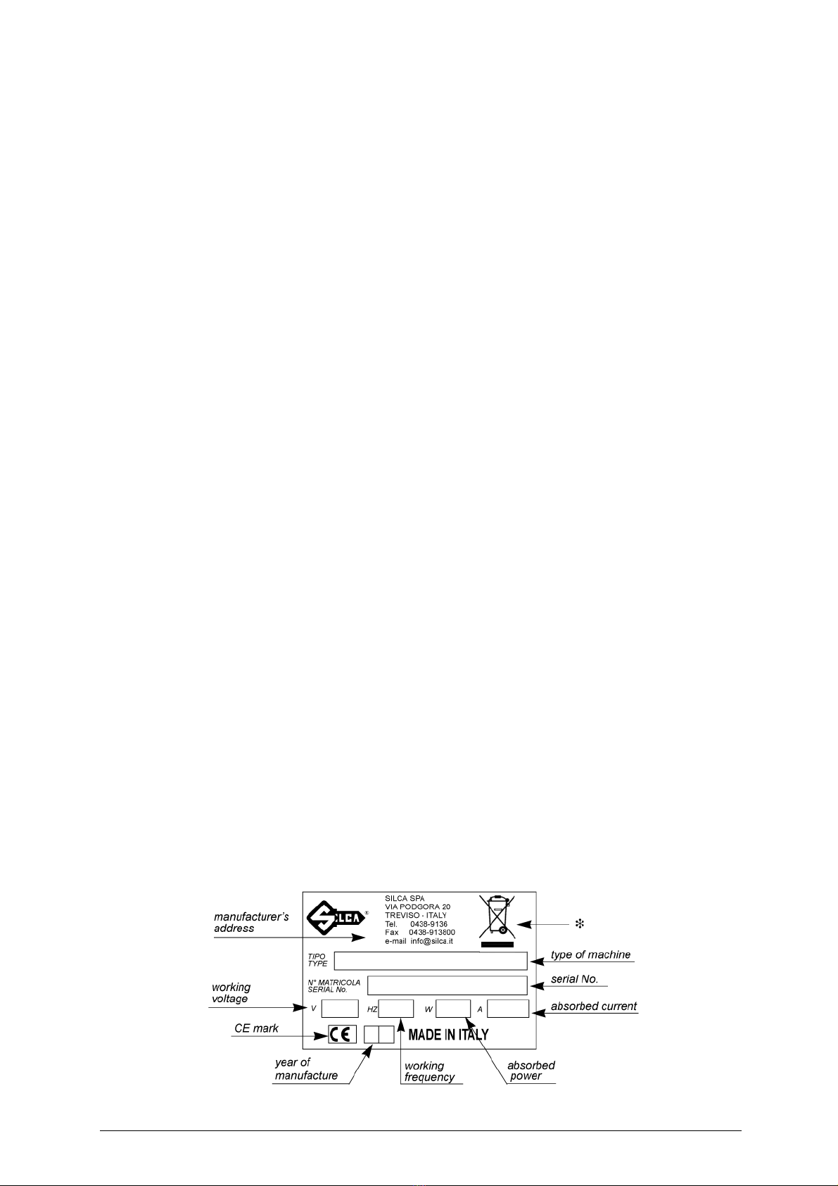
5.8 Graphics .............................................................................................12
6 MACHINE REGULATION AND UTILIZATION .............................................13
6.1 Checking and setting ..........................................................................13
6.2 Gauging ..............................................................................................13
7 CUTTING OPERATIONS ..............................................................................15
7.1 Key cutting ..........................................................................................15
7.2 Code key-cutting .................................................................................15
8 MAINTENANCE ............................................................................................16
8.1 Replacing the cutting tool ...................................................................16
8.2 Replacing the brush ............................................................................17
8.3 Replacing and/or tightening the belt ...................................................17
8.4 Replacing the tracer point ...................................................................18
8.5 Replacing the fuses ............................................................................19
8.6 Access to the lower part .....................................................................19
8.7 Replacing main switch ........................................................................20
8.8 Replacing motor/condenser ................................................................20
8.9 Replacing lamp feed (transformer) .....................................................21
8.10 Replacing lamp set/lamp protection ...................................................22
8.11 Replacing motor on switch .................................................................23
9 DISPOSAL .....................................................................................................24
10 ASSISTANCE ................................................................................................25
10.1 How to request service .......................................................................25


Operating manual - English REKORD AY
Copyright Silca 2019 3
GUIDE TO THE MANUAL
This manual has been produced to serve as a guide for users of the REKORD AY key-cutting machine.
Read it carefully; it is essential if you wish to operate your machine safely and efficiently.
Consultation
The contents of the manual are divided into sections relating to:
- Transport and handling ................................................................................................... Ch. 1
- Description of machine and safety devices .................................................................... Ch. 2-3-4-5
- Proper use of machine .................................................................................................... Ch. 6-7
- Maintenance .................................................................................................................... Ch. 8
Technical terms
Common technical terms are used in this manual. To assist those with little experience of key cutting,
below is an illustration of the terms used for the different parts of keys:
Fig. 1
1) Head
2) Rim
3) Tip
4) Cuts
2
1
3
4
NO

REKORD AY Operating manual - English
4 Copyright Silca 2019
GENERAL INTRODUCTIONS
The REKORD AY key-cutting machine has been designed according to the specifications of the
Machine Directives. From the design stage risks for the operator have been eliminated in all areas:
transport, key-cutting, regulation and maintenance.
Other risks have been eliminated by the use of protective devices for the operator.
The protective devices used are designed not to provoke further risks and, above all, they cannot be
ignored unless deliberately cut out. They do not hinder visibility of the work area.
A special adhesive label is attached to the machine warning the operator to use goggles during the
cutting operations, and this is strongly recommended in this manual.
The material used in the manufacture of this machine and the components employed during use of the
machine are not dangerous and their use complies with standards.
Use
REKORD AY is a key-cutting machine and must be installed and used according to the rules and specifi
cations established by the manufacturer.
The key-cutting machine must be used only by skilled personnel (professional use).
The key-cutting machine is designed for use on business or industrial premises (e.g. hardware shops,
key cutting centers, etc...). This equipment should not be used where children may be present.
Any other use different from that indicated in this manual will cause the forfeitureof all customers’ rights
to make claims on Silca S.p.A. and may be an unknown source of hazard for the operator or third
parties..
Negligence in the use of the machine or failure on the part of the operator to observe the instructions
given in this manual are not covered by the guarantee and the manufacturer declines all responsibility
in such cases.
It is therefore indispensable to read the operating manual carefully in order to make the best use
of the REKORD AY and benefit from its potential.
Instructions manual
The instructions manual provided with the machine is essential to its proper use and to carry out the
necessary maintenance.
We therefore recommend protecting the manual from damage in a safe sheltered place, easily to hand
for quick consultation.
Further Risks
There are further risks arising from the use of the machine (see chap. 3.1, page 8).
Protection and safety precautions for the operator
The REKORD AY key-cutting machineis built entirely to standards. The operations for which it has been
designed are easily carried out at no risk to the operator.
The adoption of general safety precautions (wearing protective goggles) and observation of the
instructions provided by the manufacturer in this manual eliminate all human error, unless deliberate.
The REKORD AY key-cutting machine is designed with features which make it completely safe in all its
parts.
•Power supply
The key-cutting machine is powered by electricity supplied through a separable earthed plug.
•Start-up
The machine is started up:
- Activating the safety main switch on the right-hand side of the machine.
- Activating the motor on switch the left-hand side.
• Maintenance
Theoperationsto regulate, service, repair and cleanthe machine have been devised in thesimplest and
safest way possible. There is no danger of removable parts being re-placed wrongly or unsafely.
• Machine Identification
The REKORD AY key-cutting machine is provided with an identification label which shows the serial
number (fig. 2).
Fig. 2
(*) see chap. 9 "DISPOSAL", page 24.

Operating manual - English REKORD AY
Copyright Silca 2019 5
1 TRANSPORT
The REKORD AY key-cuttingmachine iseasily transportedandisnotdangeroustohandle. The packed
machine can be carried by one person.
1.1 Packing
The REKORD AY is packed in a strong cardboard box, the dimensions of which are shown in fig. 3,
sufficiently robust to be used for storing the machine for long periods.
Inside the box the machine is enclosed in two expanded polymer shells. The shells and cardboard box
ensure safe transportation and protect the machine and all its parts.
Fig. 3
1.2 Transport
To avoid damaging the REKORD AY it must always be transported in its packing case. This will prevent
sudden movements or rough handling from damaging the machine, persons or things.
1.3 Unpacking
To remove the machine from the packing box:
1) cut the straps with scissors and remove.
2) prise off the staples.
3) open the box without damaging it as it may be used again (e.g. removals, dispatch to the
manufacturers for repairs or servicing).
4) check the contents of the box, which should comprise:
- 1 REKORD AY key-cutting machine packed in a protective shell.
- 1 set of documents, including: operating manual, spare parts list and guarantee.
- 1 connecting wire.
- 1 tool kit.
5) remove the key-cutting machine from the protective shell.
1.4 Handling the machine
When the REKORD AY has been unpacked, place it directly on its workbench.
This operation can be carried out by one person, firmly holding the base, and no other part, to lift and
carry the machine.
490
540
380
Keep dry This side up
Handle with care

REKORD AY Operating manual - English
6 Copyright Silca 2019
2 WORKING PARTS
Fig. 4 A - coded angle device
A1 - rotating centring clamp (position jaw)
A2 - lower jaw
A3 - tip stop
A4 - coded angle device indicator
A5 - coded spacing device drum
B - rotating centring clamp knob
C - clamp carriage
C1 - chippings tray
C2 - tool tray
D - carriage lever handle
E - coded spacing device
E1 - axis regulation grub screw
E2 - axis regulation locking screw
F - coded spacing device knob
G - tracer point
G1 - tracer point locking grub screw
G2 - centesimal ring
H - cutter
H1 - lamp
J - brush
J1 - brush cover
M - top cover
N - motor on switch
O - main switch
P - supply socket
Q - protective pad
S-motor
U - fuses
A1
A2
A4A5
E1
E2 F
A3
D
A
B
C
E
G
G1
G2
H
J
O
S
C1 C2
J1
M
F
H1
UP N
Q

Operating manual - English REKORD AY
Copyright Silca 2019 7
3 MACHINE DESCRIPTION
REKORD AY is a professional key-cutting machine for ABLOY keys. The machine comprises the
following main parts:
Main switch
The key-cutting machine is connected to a power supply socket provided with a differential switch.
Pressing the switch (O) powers the machine and illuminates the warning light (H1) to indicate that
current is on.
ATTENTION: switch (O) is electromagnetic, in the event of a power failure it goes out automatically. When
electricity is restored it must be reset manually to power the machine again.
Motor on switch
The motor on switch (N) is placed on the left-hand side of the REKORD AY key-cutting machine.
ATTENTION: the illuminated switch remains on to indicate that the key-cutting machine has been started
(cutter in motion).
Motor and transmission unit
The motor has belt transmission. The transmission unit is placed on the left of the motor and activates
the brush (J) and cutting tool (H1). These components are protected by two covers:
-protective belt cover (J1),
-top cover (M).
Mobile unit
The mobile unit comprises a carriage (C) which holds a code space setting device and a clamp for
securing the keys, with a code device for adjusting inclination (fig. 4, page 6).
The carriage (C) is fitted to the translation shaft and is moved manually by the operator.
It has been designed to avoid the accumulation of cutting dust or chippings.
The key-cutting machine has an inclined table which allows the chippings to collect in the special tray
(C1) placed under the carriage and easily removable for thorough cleaning.
W
ORKING
PARTS
The working parts are described below:
•Brush
The brush (J) is used to eliminate burrs from the cuts and is made of non-abrasive material.
• Cutting tool
The cutting tool (H) is the part of the REKORD AY used for cutting key blanks. The cutting tool is in HSS
super rapid steel and is protected by a special cover (M) to ensure safe operation.
•Tracer point
The tracer point (G) housed on the left-hand side of the machine base. A centesimal ring (G2) ensures
regulation of the depth.
• Coded angle device
The device comprises:
- a clamp (A1), connected directly to the inclination setting device, which acts as a key centring device
and tip stop.
- a jaw (A2) with which to secure the key, activated by knob (B).
• Coded spacing device
The code device comprises a knob (F) to activate a graduated slide which determines the position of
the various cuts.

REKORD AY Operating manual - English
8 Copyright Silca 2019
3.1 Further Risks
ATTENTION: there are residual hazards in the cutting zone (A) where the
cutter is located. Carefully observe the warnings in the manual.
• To fit or remove keys from the clamp STOP THE
MOVEMENT OF THE CUTTER by means of the switch (N). If
this is not done the carriage may cause a hazard by going
unexpectedly towards the moving cutter.
• After setting up the cutting code take care NOT TO MOVE
your free hand towards the cutter zone (A).
Fig. 5
3.2 Technical Data
ELECTRICAL PROPERTIES: 230V - 50/60Hz 440W 2A
CUTTING TOOL: HSS Super Rapid Steel
MOTOR: One-speed single phase 230V - 50/60Hz; 1350/1620 rpm 0,18 Kw
MOVEMENTS: manual
CLAMP: rotating
DIMENSIONS: width: 330mm - depth: 430mm - height: 270mm
SONOROUS PRESSURE: Leq. = 83 dB
WEIGHT: 18 kg.
3.3 Electric circuit
The REKORD AY key-cutting machine is provided with a single phase one-speed motor;
-1350 rpm, consumes approximately 0.18 Kw, absorption 2A (230V/50Hz)
-1620 rpm, consumes approximately 0.18 Kw, absorption 2A (230V/60Hz)
The main parts of the electric circuit on the REKORD AY are listed below:
1) Main plug with fuses
2) Safety main switch
3) Illuminated switch
4) Motor: 230V a.c. 50/60Hz
5) Condenser
6) Feeder
7) 6 LED circuit board (lamp)
A
N
black
red
Feeder (lamp)
6 LED circuit board
brown
light bluelight blue
brown
yellow/green
1
23
6
4
7
5
()
()
(lamp)

Operating manual - English REKORD AY
Copyright Silca 2019 9
4 ACCESSORIES PROVIDED
To ensure trouble-free working with the REKORD AY, it is advisable to always have certain spare parts
on hand. It is advisable to always have a tool box containing: tools, cutting tools, brushes, belts and
small replacement parts.
REKORD AY is supplied with a full range of accessories.
The accessories provided by Silca are all that is necessary to carry out the operations for which the
machine is designed.
Fig. 6
C2
5X20 FUSES (2 pcs)
4 Amps rapid (230V)
2,5 mm ALLEN KEY
3 mm ALLEN KEY
19 mm SPANNER
10 mm SPANNER
CUTTING TOOL
UNCLAMPING PIN
4 mm ALLEN KEY
5 mm ALLEN KEY
GAUGING CALLIPER

REKORD AY Operating manual - English
10 Copyright Silca 2019
5 MACHINE INSTALLATION AND PREPARATION
The REKORD AY key-cutting machine can be installed by the purchaser and does not require any
special skills.
However, some checks and preparation for use need to be carried out by the operator.
5.1 Checking for damage
The REKORD AY key-cutting machine is solid and compact and will not normally damage if transport,
unpacking and installation have all been carried out according to the instructions in this manual.
However, it is always advisable to check that the machine has not suffered any damage.
5.2 Environmental conditions
To ensure that the best use is made of the REKORD AY key-cutting machine, certain parameters must
be borne in mind:
-damp, badly ventilated sites should be avoided.
-The ideal conditions for the machine are:
- temperature: da 0 a 40°C
- relative humidity: 60% circa
5.3 Removing the blocks
Remove the protective panel (1) between the carriage and the machine body and the blocks (2 and 3)
between carriage and chippings tray (fig. 7).
Fig. 7
5.4 Positioning
Place the key-cutting machine on a horizontal surface, solid enough to take the weight (18 Kg).
To facilitate operation and maintenance, install the machine witha space of at least 200 mm on allsides
(fig. 8).
Ensure that the machine stands perfectly balanced on the four feet. Vibration is avoided when the
machine is properly set on the horizontal plane.
ATTENTION: ensure that the machine voltage is the same as that of the mains, which must be properly
earthed and provided with a differential switch.
Fig. 8
2
1
3
200 mm
200 mm
200 mm

Operating manual - English REKORD AY
Copyright Silca 2019 11
5.5 Separate parts
The separately packed parts must be installed on the REKORD AY key-cutting machine by the
purchaser, as follows:
Connection wire
Connect the key-cutting machine power
cable to the electricity mains (fig. 9).
Fig. 9
Carriage lever handle
Screw the handle (D) onto the carriage
lever (fig. 10).
Fig. 10
5.6 Description of work station
The key-cutting machine needs only one operator, who has the following controls at his/her disposal:
- Switch on the lamp by activating the main switch (O) located on the right-hand side of the machine.
- The motor on switch (N), located on the left-hand side of the machine has a warning light to show
that the key-cutting machine is live.
-Carriage handle lever (D).
Fig. 11
power
cable electricity supply
D
D
O
N

REKORD AY Operating manual - English
12 Copyright Silca 2019
5.7 Connection to the mains
For the safety of the operator and the machine it is important to ensure that the machine is connected
to the proper mains voltage by means of an earthed differential switch.
5.8 Graphics
THE USE OF
PROTECTIVE GOGGLES IS
COMPULSORY
MOTOR SERVICE LABEL
MASS-RPM-FUSIBLES LABEL

Operating manual - English REKORD AY
Copyright Silca 2019 13
6 MACHINE REGULATION AND UTILIZATION
6.1 Checking and setting
The cutting tool on the REKORD AY is the part used to cut the key blanks and should be periodically
checked and replaced, if necessary.
Every time the cutting tool is changed, and during periodical operational tests, check calibration.
Fig. 12
6.2 Gauging
The REKORD AY key-cutting machine requires two types of calibration: axis and depth.
Axial gauging
Axial gauging is regulation of the position of the cutting spaces (fig. 12 - A).
Axial gauging regulation
To regulate the axial gauging, proceed as follows:
ATTENTION:
disconnect the machine from the mains
.
1) set up the coded spacing device (fig. 13) by means of the knob (F) so that the indicator "5" is aligned
with position "2”.
2) place the gauging calliper provided in the clamp (A1) (fig. 14), pushing towards the side of the tip stop
(A3), and secure by turning the knob (B).
3) take the carriage towards the cutting tool and place the tracer point (G) all the way into the locating
groove (E3) (fig. 15, page 14).
4) check that the cutting tool enters clearly into the groove in the gauging calliper. If adjustment is
necessary, loosen screw (E2) and adjust axial gauging by means of the grub screw (E1) (fig. 13).
5) when gauging is complete, tighten the screw (E2) well.
Fig. 13
Fig. 14
AB
view from the tip
E3
Q
F
E2
E1
Q1
gauging
caliper
groove
A3
B
A1

REKORD AY Operating manual - English
14 Copyright Silca 2019
Depth setting
Depth setting is regulation of the cutting depth
(fig. 12 - B).
Usually depth setting is not necessary during normal use of the machine. However, if the tracer point is
replaced or an optional carriage is used it is advisable to check the depth settings.
Regulating depth setting
To regulate the depth settings, proceed as follows
:
ATTENTION: disconnect the machine from the mains.
1) set up the coded spacing device by means of the knob (F) so that the indicator "5" is aligned with
position "2" (fig. 13, page 13).
2) insert the tip of the gauging calliper (provided) into the rotating clamp (A1) (fig. 14), push up against
the tip stop (A3) and lock in the calliper by turning the knob (B).
3) take the carriage towards the cutting tool and place the tracer point (G) all the way into the locating
groove (E3) (fig. 15).
4) check that the cutting tool enters clearly into the groove in the gauging calliper (fig. 15). If adjustment
is necessary, adjust axial gauging in the way described above ("Axial gauging regulation").
5) loosen the screw (G1) locking the tracer point (fig. 16).
6) use the lateral brush (J) to turn the cutting tool shaft in the opposite direction to cutting. The cutting
tool should skim the bottom of the groove on the gauging calliper. If not, turn the ring nut (G2) (fig. 16)
clockwise to move the cutting tool unit forward, or in the opposite direction to move it back.
7) when the ideal regulation has been reached, tighten the tracer point locking screw.
8) if an optional carriage is used, check that the tracer point enters freely into the locating groove (E3)
and that there is not excessive play on it. If necessary, adjust play between the locating groove and
tracer point by loosening the nut (Q) and turning grub screw (Q1) (fig. 13). When adjustment is
complete, tighten the nut (Q).
Fig. 15
Fig. 16
G2
G1
G

Operating manual - English REKORD AY
Copyright Silca 2019 15
7 CUTTING OPERATIONS
ATTENTION: to work in complete safety, pay special attention to the following recommendations:
• Always work with dry hands.
• Check that the machine is properly earthed.
• Use the protective goggles, even if the cutting tool is fitted with a protective shield.
• Start the motor only when all the operations with the carriage have been carried out
(securing keys, etc.).
• Keep hands away from the cutting tool when in motion.
7.1 Key cutting
Placing keys into clamp
Place the key blank into the clamp, pushing against the side of the tip stop (A3) and secure by turning the
knob (B) (fig. 17).
Fig. 17
7.2 Code key-cutting
Important note:
ABLOY keys can feature two types of cut which differ only in the distance
between the first cut and the tip of the key. This distance can be 3 or 5 mm (fig. 12-A). To cut
keys with 3 mm use mark 3 on the locator (fig. 13) as a reference for positioning the key. For 5
mm keys, use mark 5 (fig. 13)
.
To code cut a key blank proceed as follows:
1) set the cutting position on the space code device by means of knob (E1) (fig. 17). Exert pressure on
knob (B) to turn the rotating clamp (A1) until the code for the inclinations marked on the drum (A5) is
aligned with the indicator (A4).
2) activate the machine by pressing the motor/brush start switch (N) (fig. 4, page 6).
3) move the carriage towards the cutting tool, making sure that the tracer point slides right into the notch
on the locator (fig. 17). Make the cut and pull back the carriage.
4) go on to the following position and repeat the cutting operation with the corresponding code, and so
on until the key has been cut.
5) pull the carriage back, turn off the machine, loosen the clamp (A1) and remove the key.
A3
B
locator
E1
A4A5
key blank
B
A1

REKORD AY Operating manual - English
16 Copyright Silca 2019
8 MAINTENANCE
ATTENTION: for repairs or replacement of parts for maintenance, the ‘CE’ mark is guaranteed only if original
spare parts provided by the manufacturer are used.
Although the REKORD AY key-cutting machine does not require special maintenance, it is advisable to
check and, if necessary, replace the parts subject to wear, such as: the belt, cutting tool, brush, tracer
point. Replacement is simple and can be carried out by the operator.
CLEANING
Keep the carriage and clamps free of chippings from the cutting operations by cleaning with a dry brush.
ATTENTION: do not use compressed air!
ATTENTION: to keep the machine well maintained we recommend using protective oil, e.g. WD40 or similar,
applied to the burnished mechanical parts. This prevents oxidation of the parts in question
(clamps, guides, carriages, etc.). Do not contaminate the electronic parts with the oil.
Before starting any type of maintenance (checks or replacements), read the instructions below:
-never carry out maintenance or servicing with the machine switched on.
-always remove the mains plug.
-follow all the instructions in the manual to the letter.
-use original spare parts.
-always check that any screws or nuts removed when replacing a piece are properly tightened.
8.1 Replacing the cutting tool
In order to substitute the cutting tool you don’t need to remove the cutting tool cover.
To replace a worn cutting tool, proceed as follows:
ATTENTION: turn off the machine and disconnect the supply wire.
1) Slot the locking rod (standard) into the hole of the cutting tool shaft (fig. 18).
2) Use the spanner provided to loosen the cutting tool locking the nut.
ATTENTION: the thread is left-handed.
3) Remove the worn cutting tool.
4) Carefully clean the new cutting tool and its seat.
5) Install the new cutting tool and tighten the nut.
ATTENTION: the tool rotates clockwise.
6) Remove the locking pin.
Fig. 18
locking rod
tighten
loosen

Operating manual - English REKORD AY
Copyright Silca 2019 17
8.2 Replacing the brush
When the brush no longer cleans off the burrs it must be replaced as follows:
ATTENTION: turn off the machine and disconnect the supply wire.
1) Place the locking rod (provided) in position on the motor shaft.
2) Use the Allen wrench (provided) to loosen the screw holding the brush in place (fig. 19).
3) Replace the brush and tighten the screw with the Allen wrench.
4) Remove the spanner from the motor shaft.
Fig. 19
8.3 Replacing and/or tightening the belt
Worn or loose belts must be replaced or adjusted so as to ensure safe and proper operation of the
cutting tool/ brush.
Tension:
ATTENTION: turn off the machine and disconnect the supply wire.
1) Remove the two protective pads (Q) (fig.4, page 6).
2) Loosen the 3 screws (M1) and remove the top cover
(M).
3) Loosen the 4 screws (S1) of the plate motor (fig. 22).
4)
Push the motor down until the proper belt tension is
obtained.
5) Tighten the four screws.
Fig. 20
Replacement:
ATTENTION: turn off the machine and disconnect the supply wire.
1) Remove the two protective pads (Q).
2) Loosen the 3 screws (M1) and remove the top cover
(M).
3) Remove the brush (fig. 19).
4) Remove the 3 screw (M2) (fig. 19) to remove the
protective cover (fig. 21)
5)
Loosen the 4 screws (S1) of the plate motor (fig. 22)
6) Raise the motor and remove the worn belt.
7) Fit the new belt.
8)
Replace the motor in its previous position.
9) Tighten the 4 screws.
10)Replace the belt cover
11)Replace the brush
12)Replace the top cover
Fig. 21
locking rod
brush holding
screw
tighten
loosen
M1
M2

REKORD AY Operating manual - English
18 Copyright Silca 2019
Fig. 22
FOR VERSIONS WITH BELT TIGHTENERS (P1) (fig. 23)
- Loosen the screw (P2) and raise the belt tightener in order
to remove the belt.
- Push the belt tightener downwards to tighten the belt.
- Secure the belt tightener with the screw (P2).
Fig. 23
FOR VERSIONS WITH BELT TIGHTENERS (P1)
(fig. 23)
- Push the belt tightener downwards to tighten the belt.
- Secure the belt tightener with the screw (P2).
8.4 Replacing the tracer point
To replace the tracer point (G) (fig. 25), proceed as follows:
ATTENTION: turn off the machine and disconnect the supply wire.
1) Remove the two protective pads (Q).
2) Loosen the 3 screws (M1) and remove the top cover (M).
3) Loosen the screw (K1).
4) Loosen the grub screw (G1).
5) Loosen the tracer point by turning it anticlockwise until is fully released.
6) Fit the new tracer point and screw down to the end of run.
7) Tighten the grub screw (G1).
8) Tighten the screw (K1).
9) Re-set the machine as described in chap. 6, page 13.
Fig. 24
Fig. 25
S
S1
P2
P1
K1
G2 G1 G
Table of contents
Other Silca Cutter manuals

Silca
Silca D429724XA User manual

Silca
Silca Unocode 299 User manual

Silca
Silca Delta 2000 MC User manual

Silca
Silca FUTURA PRO User manual

Silca
Silca Delta 2000 AY User manual

Silca
Silca Unocode 399 Plus User manual

Silca
Silca Matrix Evo User manual

Silca
Silca UC 199 User manual

Silca
Silca Futura Auto User manual

Silca
Silca Idea User manual

Silca
Silca Matrix One User manual

Silca
Silca Triax Pro User manual

Silca
Silca Fastbit User manual

Silca
Silca OLYMPIC User manual

Silca
Silca POKER PRO User manual

Silca
Silca Unocode PRO User manual

Silca
Silca OPERA IV User manual

Silca
Silca Technica EU User manual

Silca
Silca Futura Auto User manual

Silca
Silca Twister II NA User manual