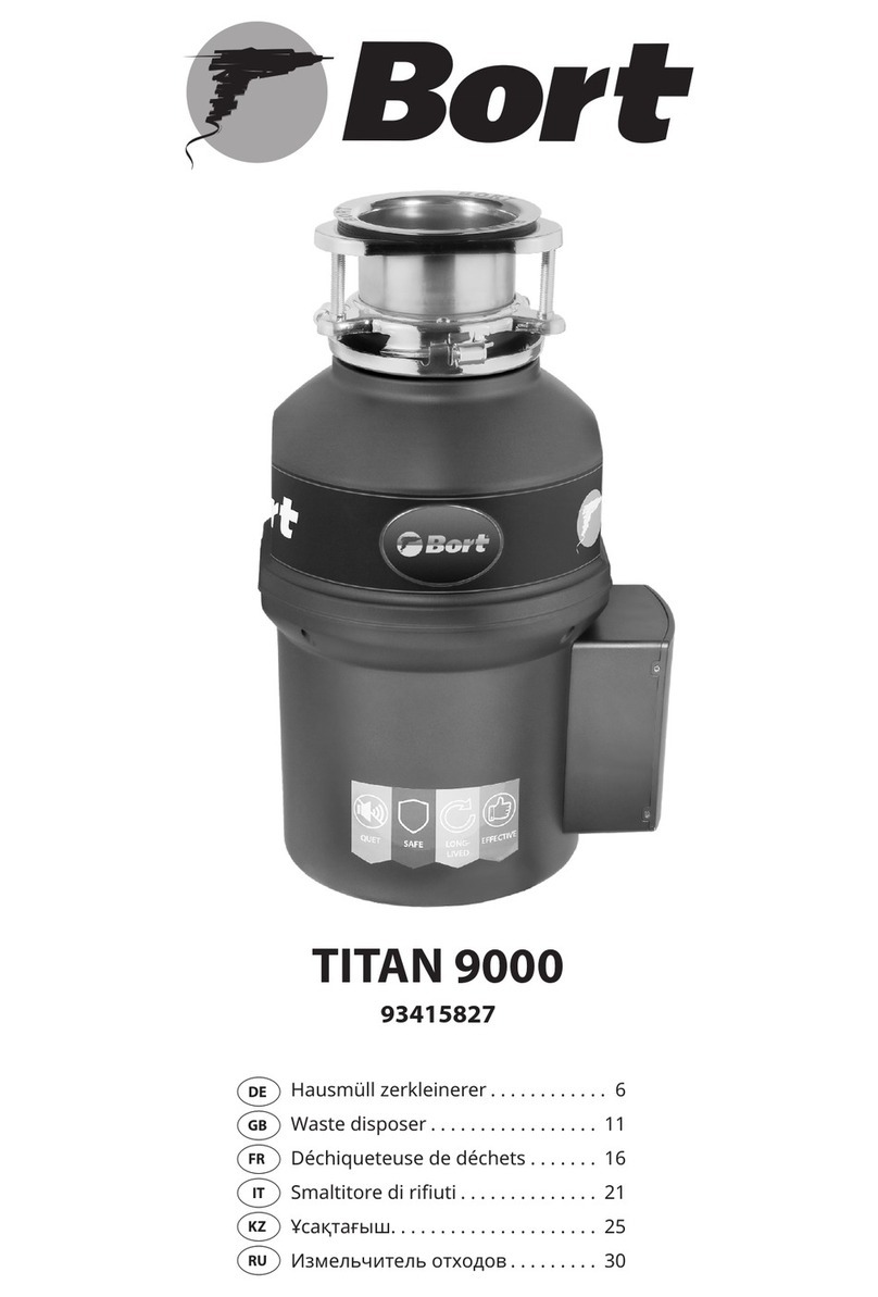
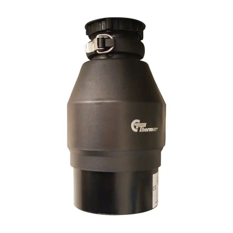
Bort MASTER ECO User manual

MASTER ECO
91275752
ALLIGATOR
93410754
ALLIGATOR Plus
93410761
Alligator Max
93410778
DE. Hausmüll zerkleinerer . . . . . . . . . 5
EN. Waste disposer . . . . . . . . . . . . . . . .9
FR. Déchiqueteuse de déchets . . . .13
RU. Измельчитель отходов . . . . . . 17

2 3
1 2 3 4 5
MASTER ECO 360 mm 160 mm 130 mm 120 mm 130 mm
Alligator 350 mm 180 mm 130 mm 190 mm 155 mm
Alligator Plus 350 mm 180 mm 130 mm 190 mm 155 mm
Alligator Max 365 mm 170 mm 130 mm 210 mm 155 mm
9.2
32 mm

4 5
INSTALLATIONSANLEITUNG,
INSTANDHALTUNG
UND VERWENDUNG DES ENTSORGERS
Bevor Sie das Produkt installieren, lesen Sie alles
sorgfältig durch. Installations–, Wartungs– und
Bedienungsanleitung. Vor Beginn der Arbeit Be-
stimmen Sie, welche Werkzeuge, Materialien und
Ausrüstung, die Sie brauchen.
Bevor Sie den Entsorger installieren, stellen Sie si-
cher, dass Sie alle erforderlichen Teile des Produkts
haben.
BEN ÖTIGTE WERKZEUGE UND MATERIALIEN:
Schraubendreher, Scharnierzange, Isolierband,
Schutzbrille
ERFORDERLICHE INSTRUMENTE, MATERIALIEN
UND OPTIONALE AUSRÜSTUNG:
ein Kreuzschlitzschraubendreher, ein Entwässe-
rungsbohrer, elektrische Klemme 9,5 mm, Ge-
windemuttern (2), Siphon 38 mm, Bohrer 32 mm,
Hammer, Eisensäge, Wasserschlauchklemme, Rohr-
zange, Kupfer Erdungskabel, Geschirrspüler Abus-
srohr Kit, elektrisch Schalter, Verlängerungsrohr
1. BESCHREIBUNG DES PRODUKTS ABB.1.1)
Montageeinheit
1. Stopper
2. Waschansch
3. Gummidichtungen (2)
4. Stützring
5. Montagering
6. Schrauben
7. Sicherungsring
8. Schalldämpfender Bildschirm Entsorger
9. Einbaudichtung / Schutzreektor
10. Ösen
11. Unterer Befestigungsring
12. Den Geschirrspüler entleeren
13. Auslassönung Entwässerungssystem
14. Befestigungsschrauben
15. Gummidichtung
16. Flansch
17. Abussrohr mit einem Knie
Das komplette Set nden Sie auf der Verpa-
ckung. Überprüfen Sie beim Auspacken des Ge-
rätes das komplette Set.
2. TRENNUNG DES TROPFENHORNS
BEACHTUNG!
Zum Zeitpunkt der Installation des Geräts wird
empfohlen Schutzbrille tragen.
Lösen Sie die Mutter (1) an der Oberseite der Was-
serfalle (4) mit einem Rohrschlüssel (Abb. 3.1). rela-
tive Luftfeuchtigkeit nicht mehr als 80%.
Lösen Sie die Mutter (2) auf der Oberseite desVerlän-
gerungsrohrs. Entfernen Sie das Verlängerungsrohr.
Lösen Sie die Mutter (3) an der Unterseite des Wa-
schansches.
Schieben Sie den Waschansch nach oben durch
Ablauoch der Spüle und entfernen Sie es (Abb. 3.2).
REINIGEN SIE DEN WASCHFAN–VERPACKUNGS-
ORT
Aus dem Dichtsto oder dem Müll.
HINWEIS: Es kann notwendig sein, die Ablaufboh-
rung für zu erweitern
Befestigungsvorrichtung für Befestigungsansche.
Ausrüstung für die Erweiterung der Entwässerungs-
bohrung wird separat erworben.
3. DEMONTAGE DER MONTAGEEINHEIT
Drehen Sie die Baugruppe (Abb.4.1) und lockere die
drei Befestigungsschrauben (1) Der Zugang zum
Ring5 (2).
Trennen Sie den Sicherungsring vom Flansch mit
einem Schraubenzieher. Jetzt kann die Montage-
einheit demontiert werden.
4. BEFESTIGEN SIE DIE BEFESTIGUNGSMONTA
GE WASCHEN ABB.5.1.
1. Eine oder zwei Gummidichtungen (2) unter dem
Waschansch (1) anbringen. Stelle sicher das Die
Entwässerungsönung ist nicht verstopft und auf
eingestellt Flanschscheibe / Dichtung. um zu Der
Flansch der Spüle wurde an Ort und Stelle, Sie müs-
sen es mit einer schweren Last zerquetschen.
(Um Kratzer zu vermeiden, verwenden Sie ein
Handtuch als Futter.)
2. Legen Sie den zweiten Gummiteil auf den Boden
der Spüle eine Dichtung (2), eine Kartondichtung
(optional) (3) und einen Metallstützring (4) (ache
Seite nach oben).
3. Während Sie die zweite Gummidichtung halten,
Kartonpolsterung (optional) und einen Metallstütz-
ring, legen Sie den Befestigungsring (5) auf den
Flansch der Spüle, so dass es mit dem Stützring
ausgerichtet.
4. Drücken Sie fest auf den Boden der Spüle Gummi
Dichtung, Pappdichtung, Unterstützung Ring und
Montagering schieben Sie den Sprengring (7) auf
den Flansch der Spüle es rastet in die Flanschnut
ein.
5. Ziehen Sie die drei Befestigungsschrauben (6) an
Die Befestigungsanordnung war dicht und gleich-
mäßig drückte auf die Spüle.
5. REINIGUNG DER ABLAUFROHRE
Wenn Sie das Abussrohr nicht reinigen, kann es
verstopfen.
1. Entfernen Sie den Wasserabscheider. (Abb.6.1)
2. Entfernen Sie mit einem Reiniger alle Feststoe
Niederschlag im horizontalen Teil der Entwässe-
Deutsch

6 7
rung Rohre, bewegt sich mit Seite des Siphons in
Richtung der Hauptleitung Rohr.
WENN DER GESCHIRRSPÜLER NICHT SEIN WIRD AN
DEN ENTSORGER VERBUNDEN, GEHEN SIE ZU TEIL 7
DIESER ANLEITUNG
6. ANSCHLUSS DES GESCHIRRSPÜLERS
MASCHINEN UND TRANSFERANSCHLUSS
Wenn das Spülbecken mit Flüssigkeit überfüllt ist, soll
man es zum Abfallentsorger durch die Einlauö-
nung in seinem oberen Teil anschließen. (Abb. 7.2)
Bei allen Modellen im Saugrohr gibt es Partition.
Die Partition muss entfernt werden (Abb. 7.1).
PLATTE / PARTITION ENTFERNEN
1. Legen Sie den Entsorger auf eine Seite und legen
Sie ihn Schraubenzieher in den Anschluss für den
Geschirrspüler, schieben Sie es bis es wird nicht an
der Trennwand am Ende des Abzweigrohrs anliegen.
2. Mit mehreren Hammerschlägen das Septum im
Abzweigrohr ausbrechen (Abb.7.1).
3. Entfernen Sie die geprägte Trennwand von der
Entsorgungsschale.
Wenn Sie den Geschirrspüler anschließen möchten,
muss er an den Einlass der Überlaufauslassrohre
angeschlossen werden. Zum Anschluss an den
Überlauf–Einlass entfernen Sie die Abdeckung des
Auspurohrs, indem Sie den Deckel abschrauben
(Abb.7.3).
7. ANSCHLUSS DES ENTSORGERS AN DIE
BEFESTIGUNGSEINHEIT
BEACHTUNG!
Um Verletzungen zu vermeiden, folgen Sie den An-
weisungen so dass während der Entfernung und
Installation eines Teils Dein Körper war nicht unter
dem Entsorger; Während der Installation ist es mög-
lich, es fallen zu lassen.
Entfernen Sie alle Gegenstände aus der Mahlkam-
mer Produkt vor der Installation auf der Spüle.
1. Installieren Sie das Produkt so, dass bieten einfa-
chen Zugri auf die Schaltäche „Neustart“ Motor
bendet sich im unteren Teil des Körpers. Blockiere
diesen Ort nicht mit irgendwelchen Objekten.
2. Platzieren Sie den Entsorger mit drei Halterungen
Schleifen (1) in die Gleitposition durch Montage-
schienen (2). (Abb. 8.1)
3. Heben Sie den Entsorger an, legen Sie den Deckel
ein Ende (Einbaudichtung) in der Halterung und
drehen Sie den Einstellring nach rechts (mit einem
Schraubenschlüssel oder einstellbar Zange), bis die
Montageschlaufen (3) gegenüber den Montage-
schienen xiert sind (Abb. 8.2).
Stellen Sie sicher, dass alle drei Befestigungsschlau-
fen verriegelt sind. Disponent ist installiert.
4. Lassen Sie Wasser in die Spüle laufen und prüfen
Sie die Anschlüsse auf Undichtigkeiten.
5. Setzen Sie den geräuschabsorbierenden Bild-
schirm in den Abuss ein Loch ache Seite nach
oben. (Abb. 8.3)
8. ANSCHLUSS DES AUSGANGSROHRES
Zum Abussrohr
BEACHTUNG!
• Es wird empfohlen, eine Schutzbrille zu tragen,
wenn Sie den Entsorger installieren.
• Bei allen Modellen ist das Abussrohr ange-
schlossen mit einer Schraubverbindung (Abb.9.2).
Schließen Sie zuerst die Hydraulikverriegelung an
den zerkleinerer und dann an den Abwasserablauf
an. Für den Anschluss sollte ein Siphon mit glatten
Wänden verwendet werden.
• Verwenden Sie nur ein Sanitärdichtmittel zum
Verbinden des Flansches der Spüle mit dem Ent-
sorger.
• Verwenden Sie keine Dichtstoe für Rohrgewin-
deverbindungen oder anaerobe Verschraubun-
gen Dichtstoe.
• Sie können das Produkt beschädigen.
• Überprüfen Sie den Entsorger und die Armaturen
regelmäßig auf Undichtigkeiten, da diese undicht
sind Wasser kann Sachschäden verursachen.
• Der Hersteller ist nicht verantwortlich für Sach-
schäden durch Wasserlecks.
INSTALLATION DES ABFLUSSSYSTEMS
1. Setzen Sie den Flansch (2) auf das Abussrohr
Setzen Sie die Gummidichtung (1) ein. Befestigen
Abussrohr, ziehen Sie es fest an den Körper Entsor-
ger mit Schrauben (4). (Abb.9.1)
9. ANSCHLUSS DES ENTSORGERS AN DAS
ELEKTRISCHE NETZWERK
BEACHTUNG! ELEKTRISCHER SCHOCK STROM
• Um einen Stromschlag zu vermeiden, schalten Sie
das Gerät aus, bevor Sie das Produkt installieren
oder warten.
• Wenn Sie nicht genug qualiziert sind, Einen
Elektriker rufen, um das Produkt zu verbinden an
die Macht.
• Wenn ein dreipoliger Erdungsstecker zum
Anschließen verwendet wird ein Drei–Kontakt
Steckdose mit Boden.
• Verändern Sie nicht das Design des mitgelieferten
Steckers Gerät.
• Unsachgemäße Erdung der Ausrüstung kann
einen elektrischen Schlag verursachen Strom.
• Alle elektrischen Verbindungen müssen mit den
elektrischen und Normen.
• Schließen Sie den Boden nicht an das
Versorgungsrohr an Gas.
• Schalten Sie die Verteilung nicht ein Schild,
bis Sie die installiert haben Buchsen mit
ordnungsgemäßer Erdung.
• Wenn das Netzkabel beschädigt ist, muss es im
Kundendienst ausgetauscht werden.
HINWEIS: Der Zugang zu einer geerdeten Steck-
dose ist erforderlich. Installation aller zusätzlichen
Steckdosen müssen von einem qualizierten Elekt-
riker ausgeführt werden und alle Steckdosen müs-
sen ordnungsgemäß geerdet sein.
Schalten Sie das Gerät ein / aus
In Abhängigkeit vom Modell werden die Abfal-
lentsorger mit zwei Steuerungsarten komplettiert:
Funkschalter (wird an der Wand platziert) oder Luft-
schalter.
Funkschalter (Wandschalter)
Die Abfallentsorger der „Control” und “FullControl“
Serien sind mit einem drahtlosen Wandschalter
ausgestattet.
Der Schalter sollte sich an einem gelegenen (siche-
ren für Kinder) Ort über der Tischplatte benden.
Um den Schalter an der Wand zu befestigen, ver-
wenden Sie doppelseitiges Klebeband.
Um das Gerät an– oder abzuschalten, halten Sie die
Taste 2–3 Sekunden lang gedrückt. Typ des Einspei-
seelements: Batterie; Spannung: 12V; Typ: A27
Luftschalter
Die Disposer sind mit einem luftschalter und einem
Verbindungsrohr ausgestattet. (außer „Control“ –
Serie).
INSTALLATION OF AIR SWITCH
1. Drill a hole with a diameter of 25 mm in suitable
top or top the panel of a sink. Some sinks may alrea-
dy have a suitable A hole for the opening of which
is necessary remove the cover.
2. Unscrew the nut from the body of the push but-
ton, while holding the stainless steel washer and
rubber gasket in place. Place one end of the PVC
tube on the spout on the body Press the other end
to A hole in the table top and a nut located under
the countertop. (Fig.10.2)
3. Place the push button housing in the hole and
tighten the nut underneath countertop (enough
arm eort). Do not use the key to tighten nut.
(Fig.10.3)
4. Take the other end of the duct and tightly put it
on the spout of the air switch located on the bot-
tom of the disposer. (Fig.10.4) Hand tighten the
clamping nut. The disposer installation is complete.
Before using the product, read all of the instruc-
tions. operation and safety contained in paragraph
10 of this manual. In conclusion, install the plug in
the sink in the Closed position. Fill the sink with wa-
ter, Remove the plug and check the connections on
the a water leakage.
10. ATTENTION! IMPORTANT INSTRUCTIONS
FOR
SAFETY
• If the air switch does not work, remove the plug
power supply from the outlet and check the air
duct pneumatic switch and delivered to the outlet
electricity.
• This product is designed for grinding food
residues at home; the ingress of substances other
than food into the disposer may cause injury and
/ or damage property. To reduce the risk of Do not
use a washer with an installed disposer not for
food purposes (for example, for bathing a child or
washing your head).
• Children should be supervised adults and should
not play with a disposer. To reduce the risk of injury
– It is necessary to keep a watchful eye on children
use of the product.
– If the wedging in the disposer is eliminated,
turn o the appliance and disconnect it from the
electrical network.
• Use a wrench for self–removal of jammed
waste according to description in the section
„Elimination of jamming disposer„.
• Use tongs or pliers to remove foreign objects from
the product.
• To reduce the risk of injury from particles that are
thrown out by the disposer, it is prohibited to use
grinders without noise shielding screen (Fig.8.3).
• Place the plug in the drain hole, as shown in Fig.
11.2 or 11.4. Do not allow the following items
to fall into the disposer: shells, including oyster,
caustic means for cleaning pipes or similar
chemical products, glass, porcelain or plastic,
large (hollow) bones, metal objects (bottle caps,
cans, or kitchen appliances), hot fat or other hot
liquids.
• Replace worn noise glossy screen / installation
gasket / protective reector if they are worn and
are no longer able to prevent waste or water.
• Wenn der Entsorger ausgeschaltet ist, verwenden
Sie einen Stopper, um dies zu verhindern
Fremdkörper beim Schleifen Kamera. Stellen
Sie sicher, dass die Macht des Entsorgers ist
behindert.
• Bevor Sie den Reset–Knopf drücken, den
Stau beseitigen oder Fremdkörper aus der
Zerkleinerungskammer entfernen, stellen Sie
sicher, dass Das Essen ist ausgeschaltet.
• Halten Sie Hände und Finger außerhalb der
Reichweite von Entsorgungskammer.

8 9
BRANDGEFAHR:
Um die Möglichkeit zu minimieren Nicht in der
Nähe von Feuerlöschern lagern Gegenstände wie
Lumpen, Papier oder Aerosoldosen. Lagern oder
benutzen Sie kein Benzin oder ähnliches brennbare
Dampf–Gas–Gemische und Flüssigkeit in der Nähe
des Entsorgers.
Folgendes nicht zulassen Kamera–Produkte: Far-
ben, Lösungsmittel, Haushalt Reinigungsmittel und
Chemikalien, Automobilüssigkeiten, Kunststo-
verpackungen.
HANDBUCH
1. Verwenden Sie den Luftschalter (Abb. 11.1), um
den Entsorger zu starten.
2. Senken Sie die Lebensmittelabfälle langsam in
die Kammer und installieren Sie das Filtergitter in
einer vertikalen Position (so dass es durchießt
Wasser) um Lärm zu reduzieren und möglich Wer-
fen von Abfall während des Schleifens (Abb. 11.2).
3. Nachdem der Schleifvorgang abgeschlossen ist,
schalten Sie die Entsorger und lassen Sie dasWasser
für mindestens 15 laufen s, um die Abussleitung
zu spülen.
SOLLTE
Speisereste unter Druck mahlen kaltes Wasser nicht
weniger als 6 Liter / min.
Mahlen Sie Feststoe wie kleine Knochen und
Fruchtrückstände zum Reinigen Hackkammern.
Grind Zitrusfrüchte, Melonen, Gemüse und Kaee-
bohnen.
Lassen Sie das Wasser nach dem Schleifen auslau-
fen mindestens 15 Sekunden, um den Abuss zu
spülen Pipeline.
Ziehen Sie das Produkt aus der Steckdose, bevor
Sie den festsitzenden Rotor mit einem Werkzeug
entfernen.
Speichern Sie keine Objekte unter dem Display, um
den Zugri auf die Schaltäche zu gewährleisten
Neustart.
UNTERLASSEN SIE
Verwenden Sie kein heißes Wasser beim Schleifen
Reste von Produkten (obwohl heiß Wasser durch
das Produkt zwischen Schleifen).
Schalten Sie das Wasser oder das Produkt erst aus,
wenn das Schleifen beendet ist. Es ist ein Geräusch
von laufendem Motor und Laufen Wasser.
Mahlen Sie keine großen Mengen Ei Schalen, faseri-
ge Materialien zum Beispiel Mais Schalen, Artischo-
cken, etc., um ein mögliches Verstopfen des Rohres
zu vermeiden.
Nur Lebensmittel mahlen.
Verwenden Sie dieses Gerät nicht zum Schleifen
von harten Materialien wie Glas und Glas Metall.
– in Gegenwart von Spuren der Önung des Kör-
pers des Produkts zur Selbstreparatur
Weitere Informationen zu den Garantiebedingun-
gen nden Sie in der Garantie Coupon. INSTALLATION INSTRUCTIONS, MAINTENANCE
AND USING THE DISPOSER
Before installing the product, read everything care-
fully. Installation, maintenance and use manual. Be-
fore starting work determine which tools, materials,
and equipment you need.
Before installing the disposer, make sure that you
have all the necessary parts of the product.
REQUIRED TOOLS AND MATERIALS:
screwdriver, Hinged pliers, insulation tape, protec-
tive glasses
REQUIRED INSTRUMENTS, MATERIALS AND OP-
TIONAL EQUIPMENT:
a Phillips screwdriver, a drainage drill, electrical ter-
minal 9.5 mm, threaded nuts (2), siphon 38 mm, drill
32 mm, hammer, hacksaw, water hose clamp, pipe
pliers, copper grounding wire, dishwasher drainage
pipe kit, electric switch, extension pipe
1. DESCRIPTION OFTHE PRODUCT FIG.1.1
Assembly unit
1. Stopper
2. Washing ange
3. Rubber gaskets (2)
4. Support ring
5. Mounting ring
6. Screws
7. Locking ring
8. Sound attenuating screen Disposer
9. Installation gasket / protective reector
10. Eyelets
11. Lower mounting ring
12. Drain the dishwasher
13. Outlet opening Drainage system
14. Mounting Screws
15. Rubber gasket
16. Flange
17. Drain pipe with a knee
The complete set is shown on the package. Dur-
ing unpacking the device, check the complete
set.
2. DISCONNECTION OF THE DROP HORN
ATTENTION!
At the time of installation of the device is recom-
mended Wear safety glasses. Loosen the nut (1) on
the top of the water trap (4) with a pipe wrench (Fig.
3.1). relative humidity not more than 80%. Loosen
the nut (2) on the top of the extension pipe. Re-
move the extension pipe.
Loosen the nut (3) at the bottom of the washing
ange.
Push the washing ange upwards through drain
hole of the sink and remove it (Fig. 3.2).
English
Gießen Sie niemals Fett, Öl oder Fett hinein Shell, da
dies zu Verstopfungen führen wird Entwässerungs–
und Abwassersysteme.
Befüllen Sie die Entsorgungskammer nicht mit ei-
ner großen Menge an Reinigungsmitteln Gemüse.
Schalten Sie stattdessen zuerst das Wasser ein und
Entsorger und senken Sie es allmählich Reinigung.
REINIGUNG DER ENTSORGUNGSKAMMER
Im Laufe der Zeit können Fett / Nahrungsmittelpar-
tikel in der Mahlkammer anreichern und schützen
Reektor, der einen unangenehmen Geruch verur-
sacht. Zum Reinigungsmahlkammer und Reektor:
1. Schalten Sie das GERÄT aus und trennen Sie es
vom Stromnetz.
2. Durch die Abussönung mit einem Schwamm
Zum Waschen den Boden reinigen Oberächen
Schutzreektor und Innenoberteil Kanten der
Hackkammer.
3. Setzen Sie den Stopfen in das Abussloch und
füllen Sie das Waschbecken mit halbem Wasser.
4. Mischen Sie 60 ml Backpulver mit Wasser. Schal-
ten Sie das Produkt ein und ziehen Sie den Stecker
aus der Spüle. Waschen von Fremdpartikeln.
BESEITIGUNG DES KOLBEN–ENTSORGERS
Wenn während des Betriebs der Entsorger Motor
angehalten, möglicherweise verklemmte bewegli-
che Teile.
Um Jammen zu beseitigen:
1. Schalten Sie den Entsorger aus und schalten Sie
das Wasser aus.
2. Stecken Sie ein Ende des Schlüssels in das mittle-
re Loch an der Unterseite des Produkts, um einen ei-
genständigen Stecker zu erhalten Beseitigung von
festsitzendem Abfall (Abb. 11.5). Drehen Sie den
Schlüssel vor und zurück bis so lange wie Er wird
keine volle Drehung machen. Mitnahme Schlüssel.
3. Entfernen Sie fremde Objekte aus dem Hilfe tickt
mit langen Handgrien. Geben zum Motor des
Produkts 3 bis 5 Minuten abkühlen lassen und den
roten Reset–Knopf an der Unterseite des Entsor-
gers drücken (Abb.11.6) (Wenn der Motor nicht an-
springt, überprüfen Sie die Schutzschild für die An-
wesenheit von Leistungsschalter und ausgebrannt
Sicherungen).
BEDIENUNG
Wenn Sie Wartungsarbeiten durchführen müssen
oder reparieren Sie das Produkt, wenden Sie sich an
einen autorisierten Händler Service Center oder zu
Ihrem Händler.
Die Garantie erlischt in folgenden Fällen:
– wenn das Produkt mit Beeinträchtigungen ver-
wendet wurde Anforderungen dieses Handbuchs

10 11
• The manufacturer is not responsible for damage
to property as a result of water leaks.
INSTALLING THE DRAINAGE SYSTEM
1. Put the ange (2) on the drain pipe Insert the rub-
ber seal (1). Fasten drain tube, tightly pulling it to
the body disposer with screws (4). (Fig. 9.1)
9. CONNECTING THE DISPOSER TO THE ELECTRI-
CAL NETWORK
ATTENTION! ELECTRIC SHOCK CURRENT
To prevent electric shock, turn o the power before
installing or servicing the product.
If you are not qualied enough, call an electrician to
connect the product to the power.
If a three–pin grounding–type plug is used to con-
nect a three–contact outlet with ground.
Do not modify the design of the plug supplied with
the device.
Improper equipment grounding may cause electric
shock current.
All electrical connections must comply with the
electrical and norms.
Do not connect the ground to the feed pipe gas.
Do not power on the distribution shield until you
have installed the sockets with proper grounding.
If the power cord is damaged, it must be replaced at
the service center.
NOTE: Access to a grounded outlet is required. In-
stalling all additional outlets must be carried out by
a qualied electrician, and all outlets must be prop-
erly grounded.
Turn ON/OFF device
Depending on the models BORT disposer are
equipped with two types of control: a wireless (wall)
switch or a pneumatic switch.
Wireless (wall) switch
The disposer of the “Control and FullControl” series
are equipped with a wireless wall mount switch.
The switch should be located in a convenient (safe
for children) place above the table top.
For instal the switch to the wall, use double–sided
tape.
For activate / deactivate the device, hold down the
key for 2–3 seconds.
Battery type: Voltage: 12V; Size: A27
Air switch
Disposer is equipped with an air switch and a con-
necting pipe (except“Control”series).
INSTALLATION OF AIR SWITCH
1. Drill a hole with a diameter of 32 mm in suitable
top or top the panel of a sink. Some sinks may al-
ready have a suitable A hole for the opening of
which is necessary remove the cover.
2. Unscrew the nut from the body of the push but-
ton, while holding the stainless steel washer and
rubber gasket in place. Place one end of the PVC
tube on the spout on the body Press the other end
to A hole in the table top and a nut located under
the countertop. (Fig. 10.2)
3. Place the push button housing in the hole and
tighten the nut underneath countertop (enough
arm eort). Do not use the key to tighten nut. (Fig.
10.3)
4. Take the other end of the duct and tightly put it
on the spout of the air switch located on the bot-
tom of the disposer. (Fig.10.4) Hand tighten the
clamping nut. The disposer installation is complete.
Before using the product, read all of the instruc-
tions. operation and safety contained in paragraph
10 of this manual. In conclusion, install the plug in
the sink in the Closed position. Fill the sink with wa-
ter, Remove the plug and check the connections on
the a water leakage.
10. ATTENTION! IMPORTANT INSTRUCTIONS FOR
SAFETY
• If the air switch does not work, remove the plug
power supply from the outlet and check the air
duct pneumatic switch and delivered to the out-
let electricity.
• This product is designed for grinding food resi-
dues at home; the ingress of substances other
than food into the disposer may cause injury and
/ or damage property. To reduce the risk of Do not
use a washer with an installed disposer not for
food purposes (for example, for bathing a child or
washing your head).
• Children should be supervised adults and should
not play with a disposer. To reduce the risk of in-
jury It is necessary to keep a watchful eye on chil-
dren use of the product.
• If the wedging in the disposer is eliminated, turn
o the appliance and disconnect it from the elec-
trical network. Use a wrench for self–removal of
jammed waste according to description in the
section “Elimination of jamming disposer “.
• Use tongs or pliers to remove foreign objects from
the product.
• To reduce the risk of injury from particles that
are thrown out by the disposer, it is prohibited to
use grinders withoutnoise shielding screen (Fig.
8.3). Place the plug in the drain hole, as shown in
Fig. 11.2 or 11.4.
• Do not allow the following items to fall into the
disposer: shells, including oyster, caustic means
for cleaning pipes or similar chemical products,
glass, porcelain or plastic, large (hollow) bones,
metal objects (bottle caps, cans, or kitchen appli-
ances), hot fat or other hot liquids.
ing it until it will not rest against the partition in the
end of the branch pipe.
2. With several blows of the hammer, knock out the
septum in the branch pipe (Fig. 7.1).
3. Remove the embossed partition from the dis-
poser bowl. If necessary to connect the dishwasher,
then it should be connected to the inlet of the over-
ow outlet pipes To connect to the overow inlet,
remove the exhaust pipe cover by unscrewing the
cover (Fig. 7.3).
7. CONNECTING THE DISPOSER TO THE FIXING
UNIT ATTENTION!
To avoid injury, follow the so that during the remov-
al and installation of a part Your body was not under
the disposer; during the installation it is possible to
drop it.
Remove any objects from the grinding chamber
product before installing it on the sink.
1. Install the product in such a way that provide
easy access to the restart button engine located in
the lower part of the body. Do not block this place
with any objects.
2. Place the disposer with three mounting loops
(1) into the sliding position by mounting rails (2).
(Fig. 8.1)
3. Lift the disposer, insert the top end (installation
gasket) in the mounting and turn the setting ring to
the right (with a wrench or adjustable pliers) until
the mounting loops are xed (3) with respect to the
mounting rails (Fig. 8.2).
Make sure that all three mounting loops are locked.
Disposer is installed.
4. Run water into the sink, then check the connec-
tions for leaks.
5. Insert the noise absorbing screen into the drain
hole at side up. (Fig.8.3)
8. CONNECTING THE OUTLET PIPE
• To the DRAIN PIPE ATTENTION!
• It is recommended to wear protective goggles
when installing the disposer.
• For all models, the drain pipe is connected using
a screw connection (Fig. 9.2). First connect the hy-
draulic lock to the disposer and then to the drain.
For the connection a siphon with smooth walls
should be used.
• Use a sanitary sealant only for connecting the
ange of the sink with the disposer.
• Do not use sealants for threaded pipe connec-
tions or anaerobic screwed sealants. They can
damage the product.
• Regularly check the disposer and ttings for wa-
ter leaks, since leaks water can cause damage to
property.
CLEAN THE WASH FAN WRAPPING PLACE FROMTHE
SEALANT OR THE GARBAGE.
NOTE: It may be necessary to expand the drain hole
for installation ange fastening disposer. Equip-
ment for extending the drainage hole is purchased
separately.
3. DISASSEMBLY OF THE ASSEMBLY UNIT
Turn over the assembly (Fig.4.1) and loosen the
three xing screws (1) The access to the ring (2).
Disconnect the retaining ring from the ange with
a screwdriver. Now the assembly unit can be disas-
sembled.
4. ATTACHING THE FIXING ASSEMBLY TO
WASHING Fig.5.1.
1. Install one or two rubber gaskets (2) under the
washing ange (1). Make sure that The drainage
hole is not clogged, and set to ange washer / gas-
ket. In order to The ange of the sink became in
place, you need to crush it with a heavy load. (To
avoid scratches, use a towel as a lining.)
2. Put the second rubber part on the bottom of the
kitchen sink a gasket (2), a cardboard gasket (op-
tional) (3) and a metal support ring (4) (at side up).
3. While holding the second rubber gasket, card-
board padding (optional) and a metal support ring,
put the mounting ring (5) on the ange of the sink
so that it aligned with the support ring.
4. Pressing tightly to the bottom of the sink rubber
gasket, cardboard gasket, support ring and mount-
ing ring, slide the snap ring (7) onto the ange of
the sink so that it snaps into the ange groove.
5. Tighten the three xing screws (6) to The xing
assembly was tight and evenly pressed to the sink.
5. CLEANING THE DRAIN PIPE
If you do not clean the drain pipe, it can clog.
1. Remove the water trap. (Fig.6.1)
2. Using a cleaner, remove all solid precipitation in
the horizontal part of the drainage pipes, moving
with side of the siphon towards the main pipe.
IF THE DISHWASHER WILL NOT BE CONNECTED TO
THE DISPOSER, GO TO PART 7 OF THIS INSTRUCTION
6. CONNECTING THE DISHWASHER MACHINES
AND TRANSFER CONNECTION
If the sink is full of liquid it can be discharged into
the disposer through the inlet in its upper parts.
(Fig. 7.2)
On all models inside the intake pipe there is parti-
tion. The partition must be removed (Fig. 7.1).
REMOVING THE PLATE / PARTITION
1. Place the disposer on one side and place it screw-
driver into the connection for the dishwasher, push-

12 13
Français
INSTRUCTIONS D’INSTALLATION, ENTRETIEN ET
UTILISANT LE DISPOSITIF DE DISTRIBUTION
Avant d’installer le produit, lisez tout attentivement.
Manuel d’installation, d’entretien et d’utilisation.
Avant de commencer le travail déterminer quels
outils, matériaux et équipement dont vous avez
besoin. Avant d’installer le broyeur, assurez–vous
d’avoir toutes les pièces nécessaires du produit.
OUTILS ET MATÉRIELS REQUIS:
Tournevis, Pince à charnière, ruban isolant, lunettes
de protection
INSTRUMENTS, MATÉRIAUX ET INSTRUMENTS
REQUIS ÉQUIPEMENT OPTIONEL:
un tournevis cruciforme, une perceuse de drainage,
borne électrique 9,5 mm, écrous letés (2), siphon
38 mm, foret 32 mm, marteau, scie à métaux, collier
de tuyau d’eau, pince de tuyau, cuivre l de mise à la
terre, kit de tuyau de drainage pour lave–vaisselle,
électrique interrupteur, tuyau d’extension
1. DESCRIPTION DU PRODUIT FIG.1.1
Unité d’assemblage
1. bouchon
2. bride de lavage
3. Joints en caoutchouc (2)
4. Bague de soutien
5. bague de montage
6. Vis
7. anneau de verrouillage
8. écran atténuant le son Broyeur
9. Joint d’installation / réecteur de protection
10. œillets
11. Bague de montage inférieure
12. Vider le lave–vaisselle
13. ouverture de sortie Système de drainage
14. Vis de montage
15. Joint en caoutchouc
16. Bride
17. Vidangez le tuyau avec un genou
L’ensemble complet est indiqué sur l’emballage.
Pendant le déballage de l’appareil, vériez
l’ensemble complet.
2. DÉCONNEXION DE LA CORNE DE GOUTTE
ATTENTION!
Au moment de l’installation de l’appareil est
recommandé Porter des lunettes de sécurité.
Desserrer l’écrou (1) sur le dessus du piège à eau (4)
avec une clé à pipe (Fig. 3.1). humidité relative pas
plus de 80%.
Desserrez l’écrou (2) sur le dessus du tuyau
d’extension. Retirez le tuyau d’extension.
Desserrez l’écrou (3) au bas de la bride de lavage.
Poussez la bride de lavage vers le haut à travers
vidangez le trou de l’évier et retirez–le (Fig. 3.2).
NETTOYER LE LIEU D’ENVELOPPEMENT DU
VENTILATEUR DE LAVAGE DU SCELLANT OU DES
ORDURES.
NOTE: Il peut être nécessaire d’élargir le trou de
drainage pour bride d’installation broyeur de
xation.
L’équipement pour l’extension du trou de drainage
est acheté séparément.
3. DÉMONTAGE DE L’UNITÉ D’ASSEMBLAGE
Retournez l’assemblage (Fig. 4.1) et desserrer les
trois vis de xation (1) L’accès à l’anneau (2).
Déconnecter la bague de retenue de la bride avec
un tournevis. Maintenant, l’unité de montage peut
être démontée.
4. FIXATION DE L’ENSEMBLE DE FIXATION
À LAVER FIG. 5.1.
1. Installez un ou deux joints en caoutchouc (2)
sous la bride de lavage (1). Sois sûr que Le trou de
drainage n’est pas obstrué et réglé sur rondelle /
joint à bride. An de La bride de l’évier est devenue
en place, vous devez l’écraser avec une lourde
charge. (Pour éviter les rayures, utilisez une serviette
comme doublure.)
2. Placez la deuxième partie en caoutchouc au fond
de l’évier un joint (2), un joint en carton (facultatif)
(3) et un anneau de support en métal (4) (côté plat
vers le haut).
3. Tout en tenant le deuxième joint en caoutchouc,
rembourrage en carton (facultatif) et un anneau
de support métallique, placez la bague de xation
(5) sur la bride de l’évier aligné avec l’anneau de
soutien.
4. Presser fermement au fond du caoutchouc de
l’évier
joint, joint en carton, support bague et la bague de
montage, faites glisser l’anneau élastique (7) sur la
bride de il s’enclenche dans la rainure de la bride.
5. Serrez les trois vis de xation (6) L’ensemble de
xation était serré et uniforme pressé à l’évier.
5. NETTOYAGE DU TUYAU DE VIDANGE
Si vous ne nettoyez pas le tuyau de vidange, il peut
se boucher.
1. Retirez le piège à eau. (Fig. 6.1)
2. En utilisant un nettoyant, retirez tous les solides
Précipitation dans la partie horizontale du drainage
pipes, se déplaçant avec côté du siphon vers la
principale tuyau.
SI LE LAVE–VAISSELLE NE SERA PAS CONNECTÉ À
LA RAMASSEUSE, ALLEZ À LA PARTIE 7 DE CETTE
INSTRUCTION
• Do not use this appliance to grind hard materials,
such as glass and metal.
• Never pour fat, oil or fat in shell, as this will lead to
clogging drainage and sewerage systems.
• Do not ll the disposer chamber with a large
amount of cleaning vegetables. Instead, turn on
the water rst and disposer and gradually lower
it cleaning.
CLEANING THE DISPOSER CHAMBER
Over time, fat / food particles can accumulate in the
grinding chamber and protective reector, causing
an unpleasant smell.
For cleaning grinding chamber and reector:
1. Turn o the EQUIPMENT and disconnect it from
the mains.
2. Through the drain hole using a sponge for wash-
ing, clean the bottom surfaces protective reector
and inner upper edges of chopping chamber.
3. Place the plug in the drain hole and ll the sink
with hot water halfway.
4. Mix 60 ml of baking soda with water. Turn the
product on and remove the plug from the sink.
washing of foreign particles.
ELIMINATION OF JUMMING DISPOSER
If during the operation of the disposer motor
stopped, possibly jammed moving parts.
To eliminate jamming:
1. Turn o the power of the disposer and shut o
the water.
2. Insert one end of the wrench into the center hole
on the bottom of the product for a self–contained
removal of stuck waste (Fig. 11.5). Turn the wrench
back and forth until as long as he will not make one
full turn. Take out wrench.
3. Remove foreign objects from the help ticks with
long handles. Give to the engine of the product cool
for 3–5 minutes and press the red reset button on
the bottom of the disposer (Fig.11.6) (If the engine
does not start, check the protective shield for the
presence of circuit breakers and burnt out fuses).
SERVICE
If you need to perform maintenance or repair the
product, contact an authorized service center or to
your dealer.
The warranty is canceled in the following cases:
– if the product was used with impairments require-
ments of this manual
– in the presence of traces of the opening of the
body of the product for self–repair
For more details about the terms and conditions of
the warranty, see the warranty coupon
• Replace worn noise glossy screen / installation
gasket / protective reector if they are worn and
are no longer able to prevent waste or water.
• If the disposer is switched o, use a stopper to
prevent foreign objects in the grinding camera.
Make sure that the power of the disposer is disa-
bled.
• Before pressing the reset button, cleaning the jam
or removing foreign objects from the shredding
chamber, make sure that the food is turned o.
• Keep hands and ngers out of the reach of dis-
poser chamber.
FIRE RISK:
To minimize the possibility of Do not store near re
extinguishing articles such as rags, paper or aerosol
cans. Do not store or use gasoline or other am-
mable vapor–gas mixtures and liquid near the dis-
poser. Do not allow the following camera products:
paints, solvents, household cleaning agents and
chemicals, automotive liquids, plastic packaging.
USER’S MANUAL
1. Use air switch (Fig. 11.1) for starting disposer.
2. Slowly lower food waste into the chamber and
install the lter grid in a vertical position (so that it
ows through it water) to reduce noise and possible
throwing waste during grinding (Fig. 11.2).
3. After the grinding is completed, turn o the dis-
poser and let the water run for at least 15 s to ush
the drain line.
SHOULD
Grind food waste under pressure cold water not less
than 6 liters / min.
Grind solids, such as small bones and fruit residues,
for cleaning chopping chambers.
Grind citrus fruits, melons, vegetables and coee
beans.
After the grinding is nished, let the water run out
at least 15 seconds to ush the drain pipeline.
Unplug the product from the socket before remov-
ing the seized rotor with a tool.
Do not store any objects under the display to en-
sure access to the button restart.
DO NOT
Do not use hot water when grinding remains of
products (although hot water through the product
between grinding).
Do not turn o the water or the product until the
grinding is completed, there is a noise of running
engine and running water.
Do not grind large amounts of egg shells, brous
materials, for example corn husks, artichokes, etc.,
in order to avoid possible clogging of the pipe.
Grind only food.

14 15
Interrupteur sans l (interrupteur mural)
Les broyeurs de la série“Control et FullControl”sont
équipés d’un commutateur de montage mural sans l.
L’interrupteur doit être placé dans un endroit
pratique (sûr pour les enfants) au–dessus du dessus
de la table.
Pour installer l’interrupteur au mur, utilisez du
ruban adhésif double face.
Pour activer / désactiver l’appareil, maintenez la
touche enfoncée pendant 2–3 secondes.
Type de batterie: Tension: 12 V; Taille: A 27
Interrupteur pneumatique
Les concasseurs sont équipés d’un interrupteur
pneumatique et d’un tuyau de raccordement (sauf
série “Control”).
INSTALLATION OF AIR SWITCH
1. Drill a hole with a diameter of 32 mm in suitable
top or top the panel of a sink. Some sinks may
already have a suitable A hole for the opening of
which is necessary remove the cover.
2. Unscrew the nut from the body of the push
button, while holding the stainless steel washer and
rubber gasket in place. Place one end of the PVC
tube on the spout on the body Press the other end
to A hole in the table top and a nut located under
the countertop. (Fig. 10.2)
3. Place the push button housing in the hole and
tighten the nut underneath countertop (enough
arm eort). Do not use the key to tighten nut.
(Fig.10.3)
4.Take the other end of the duct and tightly put it on
the spout of the air switch located on the bottom of
the disposer. (Fig. 10.4) Hand tighten the clamping
nut. The disposer installation is complete. Before
using the product, read all of the instructions.
operation and safety contained in paragraph 10 of
this manual. In conclusion, install the plug in the
sink in the Closed position. Fill the sink with water,
Remove the plug and check the connections on the
a water leakage.
10. ATTENTION! IMPORTANT INSTRUCTIONS
FOR
SAFETY
• If the air switch does not work, remove the plug
power supply from the outlet and check the air
duct pneumatic switch and delivered to the out-
let electricity.
• This product is designed for grinding food resi-
dues at home; the ingress of substances other
than food into the disposer may cause injury and/
or damage property. To reduce the risk of Do not
use a washer with an installed disposer not for
food purposes (for example, for bathing a child or
washing your head).
• Children should be supervised adults and should
not play with a disposer. To reduce the risk of in-
jury It is necessary to keep a watchful eye on chil-
dren use of the product.
• If the wedging in the disposer is eliminated, turn
o the appliance and disconnect it from the elec-
trical network. Use a wrench for self–removal of
jammed waste according to description in the
section “Elimination of jamming disposer “.
• Use tongs or pliers to remove foreign objects from
the product.
• To reduce the risk of injury from particles that are
thrown out by the disposer, it is prohibited to use
grinders without noise shielding screen (Fig.8.3).
• Place the plug in the drain hole, as shown in
Fig. 11.2 or 11.4. Do not allow the following
items to fall into the disposer: shells, including
oyster, caustic means for cleaning pipes or simi-
lar chemical products, glass, porcelain or plastic,
large (hollow) bones, metal objects (bottle caps,
cans, or kitchen appliances), hot fat or other hot
liquids.
• Replace worn noise glossy screen/ installation
gasket / protective reector if they are worn and
are no longer able to prevent waste or water.
• If the disposer is switched o, use a stopper to
prevent objets étrangers dans le broyage caméra.
Assurez–vous que le pouvoir de l’éliminateur est
désactivé
• Avant d’appuyer sur le bouton de réinitialisation,
de nettoyer le bourrage ou d’enlever des objets
étrangers de la chambre de déchiquetage, as-
surez–vous que la nourriture est éteinte.
• Gardez les mains et les doigts hors de la portée de
chambre de broyeur.
RISQUE D’INCENDIE:
Pour minimiser la possibilité de Ne pas entreposer
près d’un extincteur des articles tels que des
chions, du papier ou aérosol. Ne pas stocker ou
utiliser de l’essence ou autre mélanges de gaz et
de vapeurs inammables liquide près du broyeur.
Ne permettez pas les éléments suivants produits
photographiques: peintures, solvants, produits
ménagers produits de nettoyage et produits
chimiques, liquides automobiles, emballages en
plastique.
MANUEL D’UTILISATION
1. Utiliser l’interrupteur d’air (Fig. 11.1) pour
démarrer le broyeur.
2. Réduisez lentement les déchets alimentaires
dans la chambre et installez la grille de ltre dans
une position verticale (de sorte qu’il circule à travers
• Pour tous les modèles, le tuyau de vidange est con-
necté en utilisant un raccord à vis (Fig. 9.2). Con-
nectez d’abord le verrou hydraulique au dechique-
teuse de dechets puis au drain. Pour la connexion,
un siphon à parois lisses doit être utilisé.
• Utiliser uniquement un scellant sanitaire pour
connecter la bride de l’évier avec le broyeur. Ne
pas utiliser de produits d’étanchéité pour les
raccords letés ou anaérobies vissés produits
d’étanchéité. Ils peuvent endommager le produit.
• Vériez régulièrement le broyeur et les raccords
pour détecter les fuites d’eau, car les fuites l’eau
peut causer des dommages à la propriété. Le fab-
ricant n’est pas responsable de dommages à la
propriété à la suite de fuites d’eau.
INSTALLATION DU SYSTÈME DE DRAINAGE
1. Placez la bride (2) sur le tuyau de vidange Insérer
le joint en caoutchouc (1). Boucler drainer le tube,
en le tirant fermement sur le corps broyeur avec vis
(4). (Fig. 9.1)
9. RACCORDEMENT DU DISPOSATEUR AU
RÉSEAU ÉLECTRIQUE
ATTENTION! CHOC ÉLECTRIQUE ACTUEL
Pour éviter les chocs électriques, coupez
l’alimentation avant d’installer ou de réparer le
produit.
Si vous n’êtes pas assez qualié, appelez un
électricien pour connecter le produit au pouvoir.
Si une prise de terre à trois broches est utilisée pour
connecter un trois contacts prise avec terre.
Ne modiez pas le design de la che fournie avec
le dispositif.
Mauvaise mise à la terre de l’équipement peut
causer un choc électrique actuel.
Toutes les connexions électriques doivent être
conformes aux normes.
Ne pas connecter la terre au tuyau d’alimentation
gaz.
•Ne mettez pas la distribution sous tension bouclier
jusqu’à ce que vous avez installé le prises avec une
mise à la terre appropriée.
Si le cordon d’alimentation est endommagé, il doit
être remplacé au centre de service.
REMARQUE: L’accès à une prise mise à la terre
est requis. Installation de tous les autres les
prises de courant doivent être eectuées par un
électricien qualié et toutes les prises doivent être
correctement mises à la terre.
Allumer / éteindre l’appareil
Selon les modèles, les broyeurs BORT sont équipés
de deux types de commandes: un commutateur
sans l (mural) et un commutateur pneumatique.
6. RACCORDEMENT DU LAVE–VAISSELLE
MACHINES ET RACCORDEMENT DE TRANSFERT
Si l’évier est rempli de liquide, il peut être déchargé
dans le broyeur par l’entrée dans ses parties
supérieures. (Fig. 7.2)
Sur tous les modèles à l’intérieur du tuyau
d’admission, il y a cloison. La partition doit être
supprimée (Fig. 7.1).
RETRAIT DE LA PLAQUE / CLOISON
1. Placez le broyeur d’un côté et placez–le tournevis
dans la connexion pour le lave–vaisselle, en le
poussant jusqu’à ce que il ne reposera pas contre
la partition à l’extrémité du tuyau de branchement.
2. À plusieurs coups de marteau, faire tomber le
septum dans le tuyau de dérivation (Fig. 7.1).
3. Retirez la cloison en relief du bol de broyeur. Si
nécessaire pour connecter le lave–vaisselle, il doit
être connecté à l’entrée des tuyaux de sortie de
trop–plein. Pour raccorder l’entrée de trop–plein,
retirer le couvercle du tuyau d’échappement en
dévissant le couvercle (Fig. 7.3).
7. RACCORDER L’EVACUATION À L’UNITÉ DE
FIXATION ATTENTION!
Pour éviter les blessures, suivez les de sorte que lors
du retrait et de l’installation d’une pièce Votre corps
n’était pas sous le broyeur. pendant l’installation, il
est possible de le déposer. Retirez tous les objets de
la chambre de broyage produit avant de l’installer
sur l’évier.
1. Installez le produit de manière à ce que fournir
un accès facile au bouton de redémarrage moteur
situé dans la partie inférieure du corps. Ne bloquez
pas cet endroit avec un objet
2. Placez le broyeur avec trois supports boucles
(1) dans la position de coulissement par rails de
montage (2). (Fig. 8.1)
3. Soulevez le broyeur, insérez le haut extrémité
(joint d’installation) dans le montage et tournez
la bague de réglage vers la droite (avec une clé
ou réglable pinces) jusqu’à ce que les boucles
de montage soient xées (3) par rapport aux rails
de montage (Fig. 8.2). Assurez–vous que les trois
boucles de montage sont verrouillées. Le broyeur
est installé.
4. Faites couler l’eau dans l’évier, puis vériez les
connexions pour voir s’il y a des fuites.
5. Insérer l’écran absorbant le bruit dans le drain
trou plat côté vers le haut. (Fig. 8.3)
8. RACCORDEMENT DU TUYAU DE SORTIE
• Vers le tuyau de vidange ATTENTION!
• Il est recommandé de porter des lunettes de pro-
tection lors de l’installation du broyeur.

16 17
3. Placez le bouchon dans le trou de vidange et
remplissez–le d’eau chaude à moitié.
4. Mélanger 60 ml de bicarbonate de soude avec de
l’eau. Allumez le produit et retirez la che de l’évier.
lavage de particules étrangères.
ELIMINATION DU JUMMING DISPOSER
Si pendant le fonctionnement du moteur de
broyeur arrêté, éventuellement coincé des pièces
mobiles. Pour éliminer le brouillage:
1. Éteignez le broyeur et fermez l’eau.
2. Insérez une extrémité de la clé dans le trou central
sur le bas du produit pour une solution autonome.
enlèvement des déchets collés (Fig.11.5). Tournez la
clé d’avant en arrière jusqu’à ce que aussi longtemps
que il ne fera pas un tour complet. Sortir clé.
3. Retirez les objets étrangers du aider les tiques
avec de longues poignées. Donner au moteur du
produit refroidir pendant 3–5 minutes et appuyez
sur le bouton rouge de réinitialisation sur le fond
du broyeur (Fig.11.6) (Si le moteur ne démarre pas,
vériez bouclier de protection pour la présence de
disjoncteurs et brûlé fusibles).
UN SERVICE
Si vous devez eectuer une maintenance ou réparer
le produit, contacter un autorisé centre de service
ou à votre revendeur
. La garantie est annulée dans les cas suivants:
– si le produit a été utilisé avec des déciences
exigences de ce manuel
– en présence de traces d’ouverture du corps du
produit pour l’auto–réparation
Pour plus de détails sur les termes et conditions de
la garantie, voir la garantie coupon
elle l’eau) pour réduire le bruit et possible jeter les
déchets pendant le meulage (Fig. 11.2).
3. Une fois le meulage terminé, éteignez le broyeur
et laisser l’eau couler pendant au moins 15 s pour
vider la ligne de vidange.
DEVRAIT
Broyer les déchets alimentaires sous pression eau
froide pas moins de 6 litres / min.
Broyer les solides, tels que les petits os et les résidus
de fruits, pour le nettoyage chambres à découper.
Broyer les agrumes, les melons, les légumes et les
grains de café.
Une fois le meulage terminé, laissez l’eau s’écouler
au moins 15 secondes pour vider le drain pipeline.
Débranchez le produit de la prise avant de retirer le
rotor grippé avec un outil.
Ne stockez aucun objet sous l’écran pour garantir
l’accès au bouton redémarrer.
NE PAS
N’utilisez pas d’eau chaude lors du meulage restes
de produits (bien que chaud eau à travers le produit
entre le broyage).
N’éteignez pas l’eau ou le produit tant que le
meulage n’est pas terminé, il y a un bruit de moteur
en marche et de course eau.
Nepas broyerde grandes quantitésd’œufs coquilles,
matériaux breux, par exemple blé des coques, des
artichauts, etc., an d’éviter le colmatage éventuel
de la pipe.
Ne moudre que des aliments.
N’utilisez pas cet appareil pour meuler des
matériaux durs, tels que du verre et métal.
Ne jamais verser de graisse, d’huile ou de graisse
dans shell, car cela conduira à un engorgement
systèmes de drainage et d’assainissement.
Ne pas remplir la chambre du broyeur avec
beaucoup de nettoyage des légumes. Au lieu de
cela, allumez l’eau en premier et broyeur et abaisser
progressivement nettoyage.
NETTOYAGE DE LA CHAMBRE À DISPOSITION
Au l du temps, les particules de graisse / aliments
peuvent s’accumuler dans la chambre de broyage
et protéger réecteur, provoquant une odeur
désagréable.
Pour nettoyage de la chambre de broyage et du
réecteur:
1. Éteignez l’ÉQUIPEMENT et débranchez–le du
secteur.
2. À travers le trou de vidange en utilisant une
éponge pour laver, nettoyer le fond surfaces
réecteur de protection et tige intérieure bords de
la chambre de hachage.
Smaltitore di
riuti
IT
ISTRUZIONIDIINSTALLAZIONE,MANUTENZIONE
E DI UTILIZZO DEL DISPOSITIVO
Prima di installare il prodotto, leggere attentamente
tutto Manuale di installazione, manutenzione e uso.
Prima di iniziare stabilire quali sono gli strumenti,
materiali, e attrezzature di cui si ha bisogno. Prima
di installare il dispositivo di smaltimento, assicurarsi
di essere in possesso di tutte le parti necessarie del
prodotto.
STRUMENTI E MATERIALI NECESSARI:
cacciavite, pinza a cerniera, nastro isolante, occhiali
protettivi
STRUMENTI, MATERIALI E OPTIONAL NECESSARI
DOTAZIONE:
un cacciavite Phillips, un trapano, un terminale
elettrico 9,5 mm, dadi lettati (2), sifone 38 mm,
trapano 32 mm, martello, seghetto, fascetta
stringitubo, pinze, lo di messa a terra in rame,
drenaggio della lavastoviglie kit tubi, interruttore
elettrico, estensione tubo
1. DESCRIZIONE DEL PRODOTTO FIG.1.1
Unità di assemblaggio
1. Tappo
2. Flangia di lavaggio
3. Guarnizioni di gomma (2)
4. Anello di supporto
5. Anello di montaggio
6. Viti
7. Anello di bloccaggio
8. Schermo per attenuare il suono
9. Guarnizione di installazione / riettore di
protezione
10. Occhielli
11. Anello di montaggio inferiore
12. Svuotare la lavastoviglie
13. Apertura di uscita Sistema di drenaggio
14. Viti di montaggio
15. Guarnizione di gomma
16. Flangia
17. Tubo drenante con curva
Il set completo è mostrato sulla confezione.
Quando aprite la confezione, controllate che
siano presenti tutti i pezzi.
2. DISCONNESSIONE DEL CORNO DI GOCCIA
ATTENZIONE!
Al momento dell’installazione del dispositivo è
consigliato Indossare occhiali di sicurezza. Allentare
il dado (1) sulla parte superiore del sifone (4) con
una chiave per tubi (Fig. 3.1). l’umidità non deve
superare l’80%. Allentare il dado (2) sulla parte
superiore del tubo prolunga. Rimuovere il tubo
prolunga. Allentare il dado (3) nella parte inferiore
della angia. Spingere la angia di lavaggio verso
l’alto attraverso il foro di scarico del lavandino e
rimuoverlo (Fig. 3.2). Inglese 10 no a quando non
si appoggerà alla partizione nella parte nale del
tubo di diramazione
3. SMONTAGGIO DELL’UNITÀ DI MONTAGGIO
Capovolgere il gruppo (Fig. 4.1) ed allentare le tre
viti di ssaggio (1) per accedere all’anello (2).
Scollegare l’anello di sicurezza dalla angia con un
cacciavite. Ora l’unità di assemblaggio può essere
smontata
4. ATTACCARE IL GRUPPO DI FISSAGGIO AL
LAVAGGIO Fig. 5.1.
1. Installare una o due guarnizioni di gomma (2)
sotto la angia di lavaggio (1). Assicurarsi che il foro
di drenaggio non sia ostruito e che sia impostato
sulla rondella / guarnizione della angia. Per poter
posizionare la angia nel lavandino è necessario
schiacciarlo con un carico pesante. (Per
evitare gra, utilizzare un asciugamano come
fodera.)
2. Mettere la seconda parte in gomma sul fondo del
lavello da cucina con una guarnizione (2), una
guarnizione in cartone (opzionale) (3) e un anello
di supporto in metallo (4) (lato piatto verso l’alto).
3. Tenendo la seconda guarnizione di gomma,
guarnizione in cartone (opzionale) ed un anello
di supporto in metallo, posizionare l’anello di
montaggio (5) sulla angia del lavandino in modo
che si allinei con l’anello di supporto.
4. Premendo saldamente sul fondo della gomma
di guarnizione del lavandino, guarnizione in
cartone, anello di supporto ed anello di montaggio,
far scorrere l’anello elastico (7) sulla angia del
lavandino in modo che si incastri nella scanalatura
della angia.
5. Stringere le tre viti di ssaggio (6) nché il
ssaggio non sarà stretto e uniformemente
pressato sul lavandino.
5. PULIZIA DELTUBO DI SCARICO
Se il tubo di scarico non viene pulito, può ostruirsi.
1. Rimuovere il separatore d’acqua. (Fig.6.1)
2. Utilizzando un detergente, rimuovere tutte le
precipitazioni solide nella parte orizzontale dei
tubi di drenaggio, muovendosi dai lati del sifone
andando verso il tubo principale.
SE LA LAVASTOVIGLIE DOVRA’ ESSERE CONNESSA

18 19
AL DISPOSITIVO, VAI ALLA PUNTO 7 DI QUESTE
ISTRUZIONI
6. COLLEGAMENTO DELLA LAVASTOVIGLIE E
TRASFERIMENTO CONNESSIONE
Se il lavandino è pieno di liquido, può essere
scaricato nel dispositivo attraverso l’ingresso
presente nella parte superiore. (Fig. 7.2)
In tutti i modelli all’interno del tubo di aspirazione è
presente una partizione. La partizione deve essere
rimossa (Fig. 7.1).
2. Con diversi colpi di martello, eliminare il setto nel
tubo di diramazione (Fig. 7.1).
3. Rimuovere la partizione in rilievo dal disposer.
Se desiderate collegare la lavastoviglie, dovreste
collegarlo nella parte interna dei tubi di uscita.
Per collegare la parte interna dei tubi rimuovere il
coperchio del tubo di scarico svitando il coperchio
(Fig. 7.3)
RIMOZIONE DELLA PIASTRA / PARTIZIONE
1. Posizionare il dispositivo di smaltimento su
un lato e posizionarlo con un cacciavite nella
connessione per la lavastoviglie, premere 11
• Il produttore non è responsabile per danni alla
proprietà causati da perdite d’acqua.
INSTALLAZIONE DEL SISTEMA DI DRENAGGIO
1. Inserire la angia (2) sul tubo di scarico. Inserire il
sigillante di comma (1). Fissare il tubo di scarico allo
smaltitore utilizzando delle viti (4). (Fig. 9.1)
7. COLLEGAMENTO DEL DISPOSITIVO
ALL’UNITA’ DI FISSAGGIO ATTENZIONE!
Per evitare lesioni, seguire le istruzioni in modo
che durante i processi di rimozione e l’installazione
il corpo non si a posizionato sotto lo smaltitore;
durante l’installazione potreste farlo cadere.
Rimuovere eventuali oggetti dalla camera di
macinazione prima di installarlo sul lavandino.
1. Installare il prodotto in modo tale da fornire facile
accesso al pulsante di riavvio situato nella parte
inferiore.
Non bloccare questa zona con alcun oggetto.
2. Posizionare il dispositivo di smaltimento con tre
anelli di montaggio (1) in posizione di scorrimento
mediante guide di montaggio (2). (Fig. 8.1)
3. Sollevare il dispositivo di smaltimento, inserire
l’estremità superiore (installazione guarnizione)
nel supporto e ruotare la ghiera di regolazione
a destra (con una chiave inglese o una pinza
regolabile) nché gli anelli di montaggio non siano
ssati (3) rispetto alle guide di montaggio (Fig. 8.2).
Assicurarsi che tutti e tre i circuiti di montaggio
siano bloccati. Lo smaltitore è installato.
4. Far scorrere l’acqua nel lavandino, quindi
controllare che non ci siano eventuali perdite.
5. Inserire lo schermo fonoassorbente nello scarico
rivolgendolo verso l’alto. (Fig.8.3)
8. COLLEGAMENTO DEL TUBO DI USCITA AL
TUBO DI SCARICO ATTENZIONE!
• Si consiglia di indossare gli occhiali protettivi
durante l’installazione del dispositivo di
smaltimento.
• Per tutti i modelli, il tubo di scarico è collegato
mediante
una connessione a vite (Fig. 9.1). Innanzitutto
collegare il collettore idraulico allo smaltitore e
quindi allo scarico.
Per il collegamento dovreste usare un sifone con
pareti lisce. (Fig. 9.2.)
• Utilizzare un sigillante sanitario solo per il collegare
la angia del lavandino con lo smaltitore.
• Non utilizzare sigillanti per collegare i di tubi
lettati o sigillanti avvitati anaerobici. Potrebbero
danneggiare il prodotto.
• Controllare regolarmente che non ci siano perdite
d’acqua, poiché perdite d’acqua possono causare
danni al prodotto.
PULIRE IL POSTO DI AVVOLGIMENTO DELLA
VENTOLA DI LAVAGGIO DAL SIGILLANTE O DA
RIFIUTI.
NOTA: potrebbe essere necessario espandere il
foro di scarico per l’istallazione. L’attrezzatura per
l’estensione del foro di drenaggio deve essere
acquistata separatamente.
9. COLLEGARE IL DISPOSITIVO ALLA RETE
ELETTRICA ATTENZIONE! PERICOLO DI SCOSSA
ELETTRICA
Per evitare scosse elettriche, spegnere
l’alimentazione Prima di procedere all’installazione
o alla manutenzione del prodotto.
Se non si è sucientemente qualicati,
chiamare un’ elettricista per collegare il prodotto
all’alimentazione elettrica. Se una spina con messa
a terra a tre pin per il collegamento con una presa
a tre contatti con messa a terra, non modicare il
design della spina fornita.
Un’inadeguata messa a terra dell’attrezzatura può
causare ellettroshock. Tutti i collegamenti elettrici
devono essere a norma.
Non collegarsi ai tubi del gas.
Non accendere lo scudo di distribuzione no a
quando le prese non saranno installate con la
corretta messa a terra.
Se il cavo di alimentazione è danneggiato, deve
essere sostituito dal centro servizi.
NOTA: è necessario l’accesso a una presa con messa
a terra. L’installazione di prese aggiuntive deve essere
fatta ad opera di un’elettricista qualicato e tutte le
prese devono avere una corretta messa a terra.
Accensione/Spegnimento del dispositivo
A seconda dei modelli sono disponibili i dispositivi
di smaltimento BORT dotati di due tipi di controllo:
uno con interruttore wireless (a parete) o un
interruttore pneumatico.
Interruttore wireless (a parete)
Il dispositivo di smaltimento di “AlligatorMax” è
dotato di un interruttore di montaggio a parete
wireless. L’interruttore dovrebbe essere situato in
un posto comodo (sicuro per i bambini) sopra il
piano del tavolo.
Per installare l’interruttore sulla parete, utilizzare
il nastro biadesivo. Per attivare / disattivare il
dispositivo, premere il pulsante.
Interruttore dell’aria
Lo smaltitore è dotato di un’interruttore dell’aria edi
un tubo di collegamento (tranne“AlligatorMax”).
INSTALLAZIONE DELL’INTERRUTTORE ARIA
1. Praticare un foro del diametro di 32 mm sul
top della cucina sopra o sopra il pannello di un
lavandino. Alcuni lavandini potrebbero già
avere un foro A adatto, per aprirlo sarà necessario
rimuovere il coperchio.
2. Svitare il dado dal corpo del pulsante, tenendo
la rondella in acciaio inossidabile e guarnizione di
gomma in posizione. Posizionare un’estremità del
tubo PVC sul beccuccio sul corpo Premere l’altra
estremità sul foro A nel piano e situato sotto il piano
di lavoro. (Fig. 10.2)
3. Posizionare l’alloggiamento del pulsante nel foro
e stringere il dado sotto il piano di lavoro (ci vorrà
molto olio di gomito). Non utilizzare la chiave per
serrare il dado. (Figura. 10.3)
4. Prendere l’altra estremità del condotto e inserirlo
saldamente sul beccuccio dell’interruttore dell’aria
situato nella parte inferiore del dispositivo di
smaltimento. (Fig.10.4) Stringere a mano il dado di
serraggio. L’installazione del dissipatore è completa.
Prima di utilizzare il prodotto, leggere tutte le
istruzioni, funzionamento e sicurezza contenuti nel
paragrafo 10 di questo manuale. In conclusione,
installare il plug-in in posizione Chiuso. Riempi il
lavandino con acqua, Rimuovere la spina e vericare
i collegamenti per eventuale perdita d’acqua.
10. ATTENZIONE! ISTRUZIONI IMPORTANTI PER
SICUREZZA
• Se l’interruttore dell’aria non funziona, rimuovere
la spina di alimentazione dalla presa e controllare
l’interruttore del condotto d’aria ed il collegamento
alla presa di energia elettrica.
• Questo prodotto è progettato per macinare i
residui di cibo a casa; l’introduzione di altre sostanze
che non siano cibo, può causare lesioni e / o danni
al prodotto. Per ridurre il rischio non utilizzare il
lavandino per scopi non alimentari (ad esempio,
per fare il bagno a un bambino o lavarti i capelli).
• I bambini dovrebbero essere supervisionati da
adulti e non dovrebbero giocare con lo smaltitore.
Per ridurre il rischio di lesioni è necessario tenere
d’occhio i bambini durante l’utilizzo del prodotto.
• Se è necessario eliminare dei residui, spegnere
l’apparecchio e scollegarlo dalla rete elettrica.
Utilizzare uno strumento per rimuovere i riuti
inceppati secondo quanto indicato nella sezione
“Come sbloccare un dispositivo inceppato”.
• Utilizzare delle pinze per rimuovere oggetti
estranei
• Per ridurre il rischio di lesioni causate da particelle
Che vengono espulse dallo smaltitore, è vietato
utilizzare smerigliatrici senza schermatura
antirumore (Fig. 8.3). Posizionare il tappo nel foro di
scarico, come mostrato in Fig. 11.2 o 11.4.
• Non introdurre questi elementi nello smaltitore:
conchiglie, tra cui ostriche, mezzi caustici per
la pulizia di tubi o prodotti chimici simili, vetro,
porcellana o plastica, ossa grandi (vuote), oggetti
metallici(tappidi bottiglia,lattineoelettrodomestici
da cucina), grassi caldi o altri liquidi caldi.
• Non utilizzare questo apparecchio per macinare
materiali duri, come vetro e metallo.
• Non versare mai grasso, olio o grasso solido,
poiché ciò potrebbe provocare l’intasamento dei
sistemi di drenaggio e della fognatura.
Non riempire la camera di smaltimento con una
grande quantità di scarti di verdure. Invece, accendi
prima l’acqua e lo smaltitore ed inserisci
gradualmente i riuti.
PULIZIA DELLA CAMERA DEL DISPOSITIVO
Nel tempo, le particelle di grasso / cibo possono
accumularsi nella camera di macinazione e riettore
protettivo, causando un odore sgradevole.
Per la pulizia della camera di macinazione e del
riettore:
1. Spegnere il dispositivo e scollegare
l’alimentazione.
2. Attraverso il foro di scarico, utilizzando una
spugna per lavare è possibile pulire il riettore
protettivo delle superci inferiori ed i bordi
superiori interni della camera di macinazione.
3. Posizionare il tappo nel foro di scarico e riempire
per la metà il lavandino con acqua calda.
4. Mescolare 60 ml di bicarbonato di sodio con
20 21
acqua. Accendere il dispositivo e rimuovere la spina
dal lavandino. lavaggio di particelle estranee.
COME SBLOCCARE UN DISPOSITIVO ICEPPATO
Se durante il funzionamento, il motore di
smaltimento si ferma, è probabile che si sia vericato
un intasamento. Per eliminare l’intasamento:
1. Spegnere il dispositivo di smaltimento e spegnere
l’acqua.
2. Inserire un’estremità della chiave nel foro
centrale sul fondo del prodotto per rimuovere
autonomamente i riuti bloccati (Fig. 11.5).
Ruota la chiave inglese avanti e indietro no a
quando non farà un giro completo. Estrarre la
chiave.
3. Rimuovere oggetti estranei con l’aiuto di
strumenti dotati di manici lunghi. Lasciare
rareddare il motore del prodotto per 3-5 minuti
e premere il pulsante di reset rosso sulla parte
inferiore del dispositivo di smaltimento (Fig. 11.6)
(Se il motore non si avvia, controllare lo scudo
protettivo per la presenza di interruttori automatici
e fusibili bruciati).
SERVIZIO
Se è necessario eseguire la manutenzione o riparare
il prodotto, contattare un centro di assistenza
autorizzato o il proprio rivenditore.
La garanzia viene annullata nei seguenti casi:
- se il prodotto è stato utilizzato nonostante
impedimenti segnalati dal manuale
- in presenza di tracce di apertura del dispositivo
per autoriparazione
Per maggiori dettagli sui termini e le condizioni di
garanzia, consultare il coupon di garanzia
• Sostituire lo schermo / installazione guarnizione/
riettore protettivo se usurato o non sono più in
grado di prevenire sprechi o acqua.
• Se il dispositivo di smaltimento è spento, utilizzare
un tappo per evitare che oggetti estranei cadano
nella camera di macinazione. Accertarsi che
l’alimentazione del dispositivo di smaltimento sia
disabilitata.
• Prima di premere il pulsante di ripristino, pulire
l’inceppamento o la rimuovere gli oggetti estranei
dalla camera di macinazione, assicurarsi che il
dispositivo sia spento.
• Tenere mani e dita fuori dalla portata della camera
del dispositivo di smaltimento
RISCHIO INCENDIO:
Per ridurre al minimo la possibilità, non conservare
vicino al dispositivo altricoli come stracci, carta o
lattine per aerosol. Non conservare o usare benzina
o altri materiali inammabili come miscele di
vapore-gas e liquido vicino allo smaltitore.
Non far cadere i seguenti prodotti nella camera:
vernici, solventi, detergenti per la casa e prodotti
chimici, liquidi per autoveicoli, imballaggi in
plastica.
MANUALE UTENTE
1. Utilizzare l’interruttore dell’aria (Fig. 11.1) per
avviare lo smaltitore.
2. Far scendere lentamente i riuti alimentari
nella camera ed installare la griglia del ltro in
posizione verticale (in modo che attraverso di
essa possa scorrere l’acqua) per ridurre il rumore
e rendere possibile la discesa dei riuti durante la
macinazione (Fig. 11.2).
3. Al termine della macinazione, spegnere il
dispositivo di smaltimento e far scorrere l’acqua per
almeno 15 s per sciacquare la linea di scarico.
SI DOVREBBE
Macinare i riuti alimentari facendo scorrere acqua
fredda con una pressione non inferiore a 6 litri /
min. Macinare solidi, come piccole ossa e residui
di frutta, per la pulizia delle camere macinazione.
Macina agrumi, meloni, verdure e chicchi di caè.
Al termine della macinatura, lasciare scorrere
l’acqua almeno 15 secondi per lavare la tubazione
di scarico. Scollegare il prodotto dalla presa prima
di rimuovere il rotore grippato con l’aiuto di uno
strumento.
Non conservare oggetti sotto il display per
permettere l’accesso al pulsante di riavvio.
COSA NON FARE
Non usare acqua calda durante la macinazione dei
riuti.
Non chiudere l’acqua o spegnere il dispositivo
no a quando la macinazione non è completata, il
motore è ancora in funzione e l’acqua scorre ancora.
Non macinare grandi quantità di gusci d’uovo,
materiali brosi, ad esempio bucce di mais, carcio,
ecc., per evitare possibili intasamenti del tubo.
Macinare solo cibo.
Изготовитель: BORT GLOBAL LIMITED
Room 1501, 15/F., SPA Centre, 53–55 Lockhart Road, WAN CHAI, Hong Kong
Тел/Факс +85 258 194 891
Уполномоченное изготовителем лицо: ООО «Дизайн–строй»
125222, г. Москва, Пенягинская ул., д. 18, т +7 (499) 700–10–34
,
Перед установкой изделия прочтите вниматель-
но все. Руководство по установке, обслужива-
нию и использованию. Перед началом работ
определите, какие инструменты, материалы и
оборудование Вам необходимы.
Перед установкой измельчителя убедитесь в на-
личии всех необходимых частей изделия.
НЕОБХОДИМЫЕ ИНСТРУМЕНТЫ И МАТЕРИАЛЫ:
отвертка для круглых гаек со шлицем на торце,
шарнирные плоскогубцы, изоляционная лента,
защитные очки
НЕОБХОДИМЫЕ ИНСТРУМЕНТЫ, МАТЕРИАЛЫ И
ДОПОЛНИТЕЛЬНОЕ ОБОРУДОВАНИЕ:
крестообразная отвертка, дренажный бур, элек-
трическая клемма 9,5 мм, резьбовые гайки (2),
сифон 38 мм, сверло 32 мм, молоток, ножовка,
хомут водяного шланга, трубные клещи, медный
провод заземления, комплект дренажного па-
трубка посудомоечной машины, электрический
выключатель, удлинитель сливной трубы.
1. ОПИСАНИЕ ИЗДЕЛИЯ (Рис. 1.1)
Сборочный узел
1. Пробка
2. Фланец мойки
3. Резиновые прокладки (2)
4. Опорное кольцо
5. Монтажное кольцо
6. Винты
7. Стопорное кольцо
8. Шумопоглощающий экран
Измельчитель
9. Установочная прокладка/защитный отража-
тель
10. Проушины
11. Нижнее монтажное кольцо
12. Патрубок слива–перелива
13. Выпускное отверстие
Сливная система
14. Крепежные винты
15. Резиновая прокладка
16. Фланец
17. Сливная трубка с коленом
-
. -
.
2. ОТСОЕДИНЕНИЕ СЛИВНОЙ ГОРЛОВИНЫ
!
На время установки диспоузера рекомендуется
надевать защитные очки.
Ослабьте гайку (1) на верхней части водоулови-
теля (4) при помощи трубного ключа (Рис. 3.1).
Русский Oтносительной влажности не более 80%.
Ослабьте гайку (2) на верхней части удлинитель-
ной трубы. Снимите удлинительную трубу.
Ослабьте гайку (3) в основании фланца мойки.
Протолкните фланец мойки вверх через сливное
отверстие раковины и извлеките его (Рис. 3.2).
Очистите место крепления фланца мойки от
герметика или мусора.
ПРИМЕЧАНИЕ: Возможно, возникнет необхо-
димость в расширении сливного отверстия для
установки фланца крепления измельчителя.
Оборудование для расширения сливного отвер-
стия приобретается отдельно.
3. ДЕМОНТАЖ СБОРОЧНОГО УЗЛА
ИЗМЕЛЬЧИТЕЛЯ
• Переверните сборочный узел (Рис. 4.1) и ос-
лабьте три крепежных винта (1) до тех пор, пока
не будет открыт доступ к стопорному кольцу (2).
• Отсоедините стопорное кольцо от фланца
мойки с помощью отвертки. Теперь сборочный
узел можно разобрать.
4. ПРИСОЕДИНЕНИЕ КРЕПЕЖНОГО УЗЛА
К МОЙКЕ Рис.5.1.
1. Установите одну или две резиновых про-
кладки (2) под фланец (1) мойки. Убедитесь, что
сливное отверстие не засорено, и установите в
него фланец мойки/прокладку. Для того, чтобы
фланец мойки стал на место, Вам, возможно, по-
требуется придавить его тяжелым грузом. (Во
избежание царапин используйте полотенце в
качестве подкладки.)
2. Наденьте на фланец мойки со стороны ниж-
ней части кухонной мойки вторую резиновую
прокладку (2), картонную прокладку (дополни-
тельно) (3) и металлическое опорное кольцо (4)
(плоской стороной вверх).
3. Удерживая вторую резиновую прокладку, кар-
тонную прокладку (дополнительную) и метал-
лическое опорное кольцо, наденьте монтажное
кольцо (5) на фланец мойки, чтобы оно совме-
стилось с опорным кольцом.
4. Прижав плотно к днищу мойки резиновую
прокладку, картонную прокладку, опорное коль-
цо и монтажное кольцо, надвиньте стопорное
кольцо (7) на фланец мойки так, чтобы оно за-
щелкнулось в желобке фланца.
5. Затяните три крепежных винта (6), чтобы кре-
пежный узел плотно и равномерно был прижат
к мойке.
5.
Если не прочищать сливную трубу, она может за-
биться.
1. Снимите водоуловитель. (Рис. 6.1)
2. С помощью очистителя удалите все твердые
осадки в горизонтальном участке сливной тру-

22 23
бы, двигаясь со стороны сифона по направле-
нию к основной трубе.
ЕСЛИ ПОСУДОМОЕЧНАЯ МАШИНА НЕ БУДЕТ
ПОДСОЕДИНЕНА К ИЗМЕЛЬЧИТЕЛЮ, ПЕРЕЙДИТЕ
К ПУНКТУ 7 ДАННОЙ ИНСТРУКЦИИ
6.
Если мойка переполнена жидкостью, то ее сле-
дует подключить к измельчителю через входное
отверстие в его верхней части (Рис. 7.2).
Для подключения к входу переполнения, удали-
те перегородку (Рис. 7.1).
На всех моделях внутри патрубка есть перего-
родка, которую необходимо удалить.
/
1. Положите измельчитель набок и поместите от-
вертку в патрубок, продвигая ее до тех пор, пока
она не упрется в перегородку в торце патрубка.
2. Несколькими ударами молотка выбейте пере–
городку в патрубке (Рис. 7.1).
3. Удалите выбитую перегородку из чаши дис–
поузера. Если требуется подключение посудо-
моечной машины, используйте подключение к
переливной выпускной трубе. Для подключения,
удалите заглушку выпускной трубы,отвинтив
крышку (Рис. 7.3)
7.
!
Во избежание травм следите за тем, чтобы во
время съема и установки части Вашего тела не
находились под измельчителем; во время уста-
новки возможно его падение.
Удалите любые объекты из камеры измельчения
изделия перед установкой его на мойку.
1. Установите изделие таким образом, чтобы
обеспечить легкий доступ к кнопке перезапуска
двигателя, расположенной в нижней части кор-
пуса. Не загораживайте это место какими–либо
предметами.
2. Поместите измельчитель с тремя монтажными
петлями (1) в положение для скольжения по мон-
тажным направляющим (2). (Рис. 8.1)
3. Поднимите измельчитель, вставьте верхний
конец (установочная прокладка) в крепежный
узел и поверните установочное кольцо вправо
(при помощи гаечного ключа или регулируемых
плоскогубцев) до тех пор, пока монтажные петли
не зафиксируются (3) относительно монтажных
направляющих (Рис. 8.2). Убедитесь, что все три
монтажных петли зафиксировались. Измельчи-
тель установлен.
4. Пустите воду в мойку, затем проверьте соеди-
нения на предмет утечек.
5. Вставьте шумопоглощающий экран в сливное
отверстие плоской стороной вверх. (Рис. 8.3)
8.
!
• На время установки измельчителя рекоменду-
ется надевать защитные очки.
• Ко всем моделям сливная трубка подключа-
ется при помощи винтового соединения (Рис.
9.2). Подключить гидрозатвор сначала к диспо-
узеру, а затем к канализационному сливу. Для
подсоединения обязательно следует исполь-
зовать гладкостенный сифон. Бутылочный и
гофрированный не имеют достаточной жест-
кости, а также склонны к засорам, особенно в
зоне «колена».
• Используйте сантехнический герметик только
для соединения фланца мойки с измельчите-
лем.
• Не используйте герметики для резьбовых со-
единений труб или анаэробные резьбовые
герметики.
• Они могут повредить изделие.
• Регулярно проверяйте измельчитель и фитин-
ги на наличие утечек воды, поскольку утечки
воды могут повлечь за собой ущерб имуще-
ству. Производитель не несет ответственности
за ущерб имуществу в результате утечек воды.
1. Наденьте фланец (2) на сливную трубку Вставь-
те резиновый уплотнитель (1). Закрепите слив-
ную трубку, плотно притянув ее к корпусу из-
мельчителя винтами (4). (Рис. 9.1)
9.
!
• Для предотвращения поражения электриче-
ским током, перед установкой или обслужива-
нием изделия отключите питание.
• Если Вы недостаточно квалифицированы, вы-
зовите электрика для подключения изделия к
сети.
• Если используется трехконтактная штепсель-
ная вилка с заземлением, для подключения
необходимо использовать трехконтактную ро-
зетку с заземлением.
• Не допускается внесение изменений в кон-
струкцию штепсельной вилки, поставляемой с
устройством.
• Неправильное заземление оборудования мо-
жет привести к поражению электрическим то-
ком.
• Все электрические соединения должны соот-
ветствовать электротехническим правилам и
нормам.
Изготовитель: BORT GLOBAL LIMITED
Room 1501, 15/F., SPA Centre, 53–55 Lockhart Road, WAN CHAI, Hong Kong
Тел/Факс +85 258 194 891
Уполномоченное изготовителем лицо: ООО «Дизайн–строй»
125222, г. Москва, Пенягинская ул., д. 18, т +7 (499) 700–10–34
Изготовитель: BORT GLOBAL LIMITED
Room 1501, 15/F., SPA Centre, 53–55 Lockhart Road, WAN CHAI, Hong Kong
Тел/Факс +85 258 194 891
Уполномоченное изготовителем лицо: ООО «Дизайн–строй»
125222, г. Москва, Пенягинская ул., д. 18, т +7 (499) 700–10–34
• Не подсоединяйте заземление к трубе подачи
газа.
• Не включайте питание на распределительном
щите до тех пор, пока не будут установлены ро-
зетки с надлежащим заземлением.
• В случае повреждения провода питания его за-
мену должены произвести в сервисном центре.
: Необходим доступ к заземлен-
ной розетке. Установку всех дополнительных
розеток должен выполнять квалифицированный
электрик, и все розетки должны быть надлежа-
щим образом заземлены.
/
Измельчители комплектуются пневмовыключа–
телем и присоединительной трубкой. Пневмо-
выключатель активируется/отключается посыл-
кой пневмоимпульса в блок управления.
1. Просверлите отверстие диаметром 32 мм в
подходящем месте столешницы или верхней па-
нели мойки. Некоторые мойки уже могут иметь
подходящее отверстие, для открытия которого
необходимо снять крышку.
2. Открутите гайку от корпуса нажимной кнопки,
удерживая шайбу из нержавеющей стали и рези-
новую прокладку на месте. Поместите один ко-
нец ПВХ–трубки на носик на корпусе нажимной
кнопки, а другой конец направьте в отверстие в
столешнице и гайку, находящуюся под столеш-
ницей. (Рис. 10.2)
3. Поместите корпус нажимной кнопки в отвер-
стие и затяните гайку, находящуюся под столеш-
ницей (достаточно усилия руки). Запрещается
использовать ключ, чтобы затянуть гайку. (Рис.
10.3)
4. Возьмите другой конец воздуховода и плот-
но наденьте его на носик пневмовыключате-
ля, рас–положенного на днище измельчителя.
(Рис. 10.4) Затяните рукой зажимную гайку. Уста-
новка измельчителя завершена. Перед исполь-
зованием изделия прочтите все инструкции по
эксплуатации и безопасности, содержащиеся в
пункте 10 данной инструкции. В заключение уста-
новите пробку в мойке в закрытое положение. За-
полните мойку водой, выньте пробку и проверьте
соединения на предмет протечек воды.
10. !
Если пневмовыключатель или настенный вы-
ключатель не работает, то выньте вилку шнура
питания из розетки и проверьте воздуховод
пневмовыключателя и подается ли на розетку
электрический ток.
Данный продукт разработан для измельчения
остатков пищи в домашних условиях; попадание
отличных от пищи веществ в измельчитель мо-
жет вызвать травму и/или причинить ущерб иму-
ществу. Для снижения риска получения травмы
не используйте мойку с установленным измель-
чителем не для пищевых целей (например, для
купания ребенка или мытья головы).
Дети должны находиться под присмотром
взрослых и не должны играть с измельчителем.
Для снижения риска получения травмы необхо-
димо бдительно следить за детьми при исполь-
зовании изделия.
При устранении заклиниванияа в измельчителе
перед этим выключите прибор и отсоедините
его от сети.
Используйте гаечный ключ для самостоятель-
ного удаления застрявших отходов согласно
описанию в разделе «Устранение заклинивания
измельчителя».
Для удаления посторонних предметов из изде-
лия используйте щипцы или плоскогубцы.
Для снижения риска получения травмы от ча-
стиц, выбрасываемых измельчителем, запреща-
ется использовать измельчители без установ-
ленного шумопоглощающего экрана (Рис. 8.3).
Поместите пробку в сливное отверстие, как по-
казано на Рис. 11.2 или 11.4. Не допускайте по-
падания в измельчитель следующих предметов:
раковин, в том числе устричных, каустических
средств для очистки труб или аналогичных хи-
мических продуктов, стекла, фарфора или пла-
стика, крупных (полых) костей, металлических
предметов (крышек для бутылок, консервных
банок, или кухонных приборов), горячего жира
либо других горячих жидкостей.
Произведите замену изношенного шумопогло-
щающего экрана / установочной прокладки / за-
щитного отражателя, если они изношены и уже
не способны препятствовать проникновению
или выбросу отходов и воды.
Если измельчитель выключен, используйте проб-
ку для предотвращения попадания посторонних
предметов в измельчительную камеру. Убеди-
тесь, что питание измельчителя отключено.
Перед нажатием кнопки перезапуска, прочист-
кой затора или удалением посторонних объек-
тов из измельчительной камеры убедитесь, что
питание изделия отключено.
Не допускайте попадания рук и пальцев в каме-
ру измельчителя.
:
Для минимизации возможности возникновения
пожара НЕ храните рядом с изделием воспламе-
няющиеся предметы, такие как ветошь, бумага
или аэрозольные баллончики.
Не храните и не используйте бензин или другие
легковоспламеняющиеся парогазовые смеси и
жидкости поблизости с измельчителем.

24 25
Изготовитель: BORT GLOBAL LIMITED
Room 1501, 15/F., SPA Centre, 53–55 Lockhart Road, WAN CHAI, Hong Kong
Тел/Факс +85 258 194 891
Уполномоченное изготовителем лицо: ООО «Дизайн–строй»
125222, г. Москва, Пенягинская ул., д. 18, т +7 (499) 700–10–34
Уполномоченное изготовителем лицо: ООО «Дизайн–строй»
125222, г. Москва, Пенягинская ул., д. 18, т +7 (499) 700–10–34
Eco Master Alligator Alligator
Plus
Alligator
Max
Двигатель Постоянного
тока Индукционный
Мощность 390 560 750 560
Производительность 3,2 4,2 5,2
Объем камеры 1000 1450 1 600
Скорость холостого хода 2800 1 480 1680
Материал камеры Нержавеющая сталь
Функция авто–реверса – – – +
Усилитель мощности (бустер) – – – +
Автоматическое выключение – – – +
Система шумоизоляции – + + +
Система защиты от
перегрузки и заклинивания + + + +
диаметр сливного отверстия 3 1/2" (90мм) 3 1/2" (90мм) 3 1/2" (90мм) 3 1/2" (90мм)
Уровень шума 58 55
Напряжение сети Вт/Гц 220–240/50–60 220–240/50–60 220–240/50–60 220–240/50–60
Вес изделия, кг 4,5 9 10 10,3
Не допускайте попадания следующих веществ в
камеру изделия: краски, растворители, бытовые
чистящие средства и химические вещества, ав-
томобильные жидкости, пластиковая упаковка.
1. Используйте настенный выключатель или
пневмовыключатель (Рис. 11.1) для запуска из-
мельчителя.
2. Медленно опустите пищевые отходы в камеру
и установите фильтрующую сетку в вертикаль-
ное положение (чтобы через нее протекала
вода) для уменьшения шума и возможного вы-
броса отходов во время измельчения (Рис.11.2).
3. После завершения измельчения выключите
измельчитель и пустите воду не менее чем на 15
с, чтобы промыть сливной трубопровод.
...
Измельчать пищевые отходы под напором хо-
лодной воды не менее 6 литров/мин.
Измельчать твердые вещества, такие как не-
большие кости и остатки фруктов, для очистки
камеры измельчения.
Измельчать цитрусовые, дыни, овощи и кофей-
ные зерна.
После завершения измельчения пустить воду не
менее чем на 15 с, чтобы промыть сливной тру-
бопровод.
Выключать из розетки изделие перед устране-
нием заедания ротора с помощью инструмента.
Не хранить каких–либо предметов под диспо-
узером, чтобы обеспечить доступ к кнопке пере-
запуска.
...
Не используйте горячую воду при измельчении
остатков продуктов (хотя допускается течение
горячей воды через изделие между измельче-
ниями).
Не выключайте воду или изделие до заверше-
ния измельчения, при этом должен быть слышен
шум работающего двигателя и бегущей воды.
Не измельчайте большие объемы яичной скор-
лупы, волокнистых материалов, например куку-
рузной шелухи, артишоков и т. д., во избежание
возможного засора трубы.
Измельчайте только пищевые продукты.
Не используйте этот прибор для измельчения
твердых материалов, например стекла и металла.
Никогда не выливайте сало, масла или жир в
раковину, поскольку это приведет к засорению
системы слива и канализации.
Не заполняйте камеру измельчителя единов-
ременно большим количеством очистков от
овощей. Вместо этого сначала включите воду
и измельчитель и постепенно опускайте в него
очистки.
С течением времени частицы жира/пищи могут
скапливаться в камере измельчения и защитном
отражателе, вызывая неприятный запах. Для
очистки измельчительной камеры и отражателя:
1. Выключите ИЗДЕЛИЕ и отключите его от сети.
2. Через сливное отверстие, используя губку для
промывки, произведите очистку нижней поверх-
ности защитного отражателя и внутренней верх-
ней кромки камеры измельчения.
3. Поместите пробку в сливное отверстие и на-
полните мойку горячей водой наполовину.
4. Смешайте с водой 60 мл пищевой соды. Вклю-
чите изделие и удалите пробку из мойки для
промывки посторонних частиц.
Если во время работы измельчителя двигатель
остановился, возможно заклинивание подвиж-
ных частей.
Для устранения заклинивания:
1. Отключите питание измельчителя и перекрой-
те воду.
2. Вставьте один конец гаечного ключа в цен-
тральное отверстие на дне изделия для само-
стоятельного удаления застрявших отходов
(Рис.11.5). Поворачивайте гаечный ключ назад и
вперед до тех пор, пока он не сделает один пол-
ный оборот. Выньте гаечный ключ.
3. Достаньте посторонние предметы при по-
мощи клещей с длинными ручками. Дайте дви-
гателю изделия остыть в течение 3–5 минут и
нажмите красную кнопку перезапуска на дне
измельчителя (Рис. 11.6) (если двигатель не за-
пускается, проверьте распределительный щит
на наличие сработавших
автоматических выключателей и перегоревших
предохранителей).
Если требуется выполнить обслуживание или
ремонт изделия, обратитесь в авторизованный
сервисный центр или к своему дилеру.
Гарантия аннулируется в следующих случаях:
– если изделие использовалось с нарушениями
требований данной инструкции
– при наличии следов вскрытия корпуса изделия
для самостоятельного ремонта
Более подробно условия действия гарантии из-
ложены в прилагаемом к изделию гарантийном
талоне.
Изготовитель: BORT GLOBAL LIMITED
Room 1501, 15/F., SPA Centre, 53–55 Lockhart Road, WAN CHAI, Hong Kong
Тел/Факс +85 258 194 891
Уполномоченное изготовителем лицо: ООО «Дизайн–строй»
125222, г. Москва, Пенягинская ул., д. 18, т +7 (499) 700–10–34
Уполномоченное изготовителем лицо: ООО «Дизайн–строй»
125222, г. Москва, Пенягинская ул., д. 18, т +7 (499) 700–10–34

27
DE
1. BORT GLOBAL LIMITED bietet 2 Jahre Garantie auf das komplette
Sortiment an, ausgehend vom Verkaufsdatum. Für das Gerät, das mit
professionellen, gewerblichen Zielen verwendet wird, erstreckt sich
die Garantie nicht, es unterliegt lediglich einer gebührenpichtigen
Reparatur.
2. Eine Nutzung des Gerätes für den Hausbedarf charakterisiert eine
Beschränkung in der Arbeitszeit und damit ist seine Nutzung für den
Hausbedarf für nicht mehr als 40 Stunden Nutzungsdauer gemeint,
dabei muss man für jede 15 Minuten ununterbrochener Arbeit eine
Pause von 10–15 Minuten machen. Die Nutzung des Gerätes zuwi-
der dieser Bedingung ist eine Regelverletzung der entsprechenden
Nutzung (die gegebene Bedingung erstreckt sich nicht auf Pumpen,
Generatoren, Ladevorrichtungen und ähnliche Ausrüstungen). Die
Lebensdauer des Gerätes unter Beachtung der obengenannten Bedin-
gung beträgt 5 Jahre.
Beim Kauf des Gerätes wird ein Garantiekupon ausgefüllt (auf jeden
Fall müssen das Verkaufsdatum, das Modell, die Seriennummer des
Gerätes angegeben und die übrigen Felder ausgefüllt werden). Bitte
bewahren Sie den Kupon und den Kassenbon während der Garantie-
frist für die Vorlage im Servicezentrum auf.
Ein Elektrogerät wird zur Garantiereparatur lediglich in zusammen-
gebauter Form angenommen, mit den ersetzbaren Arbeitsvorrich-
tungen und den Befestigungselementen (Reifen, Kreissägeblätter,
Ketten, Messer, Trimmerköpfe, Düsen, Kettenräder, Bolzen, Muttern,
Befestigungsansche des Gerätes).
3. Während der Garantiefrist werden kostenfrei behoben:
• Beschädigungen des Gerätes, die wegen der Verwendung von
minderwertigem Material entstanden sind.
• die Montagefehler, die durch Verschulden des Herstellers ent-
standen sind.
4. Die Garantie erstreckt sich nicht:
• Auf Störungen am Gerät, die durch das Nichtbefolgen der Be-
triebsanweisungen hervorgerufen werden.
• Auf mechanische Beschädigungen (Risse, Kratzer, mechanische
Beschädigungen der Netzkabel, mechanische Beschädigungen
des Körpers u.ä.) und Beschädigungen, die durch Einwirkung von
aggressiven Mitteln und hohen Temperaturen hervorgerufen
wurden, durch Eindringen von Flüssigkeiten, fremdartigen Ge-
genständen in die Ventilationsgitter des Elektrogerätes, sowie Be-
schädigungen, die infolge falscher Aufbewahrung eingetreten sind
(Korrosion von Metallteilen u.ä.);
• Auf Geräte mit Schäden, die infolge von Überlastung entstanden
sind (gleichzeitiger Ausfall des Rotors und Stators) oder unsach-
gemäßer Nutzung (Nutzung eines abgestumpften, unpassenden,
nicht ausbalancierten, falsch ausgewählten Ersatzgerätes), unge-
nügender technischer Wartung oder Pege, Anwendung des Ge-
rätes für einen Zweck, für den es nicht bestimmt ist (Nutzung zur
ArbeitaneinemMaterial,für eine Arbeit,fürdiedasGerätnichtvor-
gesehen ist, u.ä.), sowie der Instabilität der Parameter des Strom-
netzes, die die Normen überschreiten, die durch EN61000–3–2,
EN 61000–3–3 bestimmt werden. Zu den unbedingten Merk-
malen der Überlastung des Erzeugnisses gehören unter an-
derem: Veränderungen des äußeren Aussehens, Deformation
oder Schmelzen von Teilen und Baueinheiten des Erzeugnisses,
Schwärzung oder Verkohlung der Leitungsisolierung unter Ein-
wirkung hoher Temperatur.
• Auf schnellverschleißende Erzeugnisse und Materialien (Kohlen-
bürsten, Riemen, Gummidichtungen, Netze, Schutzmäntel, Büh-
nen, Reifen, Zahnräder, Lager, Buchsen, Heizspiralen, Scheiben,
Rollen, Stöcke, Sperrknöpfe u.ä.), auf Teile (Zahnräder, Wellen,
Lager, Stöcke, Rollen u.ä.), die dem Verschleiß infolge der Qua-
lität des Schmiermittels ausgesetzt sind, sowie auf ersetzbares
Zubehör (Bohrpatronen, SDS–Patronen, Bühnen, Zangen, Reifen,
exible Wellen, Batterien, Ladevorrichtungen u.ä.) und Ausga-
bematerialien (Messer, Laubsägen, Schleifmittel, Sägeblätter,
Bohrer, Bohrmeißel, Schmierstoe u.ä.), mit Ausnahme von Fällen
der mechanischen Beschädigungen der oben angeführten Er-
zeugnisse, die infolge des Garantieverstoßes des Elektrogerätes
geschahen;
• Den natürlichen Verschleiß des Gerätes oder seiner Teile (Qualität
der Ressourcen, starke innere oder äußereVerschmutzung, Quali-
tät des Schmiermittels);
• Auf ein Gerät, das während der Garantiefrist von Personen oder
Organisationen geönet oder repariert wurde, die keine juristi-
sche Vollmacht für die Durchführung der Reparatur besitzen;
• Auf ein Gerät mit einer entfernten, ausgewaschenen oder geän-
derten werkseigenen Nummer, sowie, wenn die Daten auf dem
Elektrogerät mit den Daten auf dem Garantiekupon nicht über-
einstimmen;
• Auf eine vorbeugende Wartung des Elektrogerätes, zum Beispiel:
Reinigung, Wäsche, Schmieren.
5. Der Betrieb des Elektrogerätes mit Merkmalen eines Defektes ist
nicht zulässig (erhöhte Funkenbildung, Brandgeruch, erhöhter Lärm,
starke Vibration, ungleichmäßiges Drehen, Leistungsverlust). Der
Betrieb des Elektrogerätes bei Vorhandensein von mechanischen
Beschädigungen des Kabels der Stromversorgung (Risse, Kratzer,
Brüche der Bänder), des Netzsteckers, sowie von Beschädigungen
des Körpers des Elektrogerätes ist verboten.
6. Fehlerhafte Baueinheiten der Geräte werden in der Garantiezeit
kostenlos repariert oder werden durch neue ersetzt. Die Entschei-
dung über die Frage der Zweckmäßigkeit des Ersatzes oder der Re-
paratur bleibt dem Servicedienst vorbehalten.
Die Beseitigung der Schäden, die von uns als Garantiefall anerkannt
werden, erfolgen wahlweise durch die Gesellschaft BORT GLOBAL
LIMITED mittels einer Reparatur oder des Ersatzes des fehlerhaften
Gerätes. Die ersetzten Geräte und ihre Teile gehen ins Eigentum des
Servicedienstes der BORT GLOBAL LIMITED über.
7. Empfehlungen für die vorbeugende Wartung des Elektrogerätes:
Für das Elektrogerät wird die Durchführung einer regelmäßigen
vorbeugenden Wartung empfohlen (Reinigen, Wäsche, Ersatz des
Schmiermittels im Getriebe und den Lagern; Ersatz von Schnellver-
schleißteilen). Das gewährleistet die tadellose Arbeit des Elektroge-
rätes während der gesamten Laufzeit. Die Periodizität der Durch-
führung der vorbeugenden Wartung ist bei nomineller Belastung
der Frist des natürlichen Verschleißes der Kohlenbürsten gleich. Die
Arbeit für die Durchführung der vorbeugenden Wartung wird laut
der geltenden Preisliste des Servicezentrums bezahlt. Die bei der
Durchführung der vorbeugenden Wartung aufgetauchten Schäden,
die unter die Gültigkeitsdauer der Garantieverpichtungen Fallen,
werden kostenlos behoben. Schäden, die nicht unter die Garantie-
frist fallen und bei der Diagnostik entdeckt werden, werden laut Ab-
kommen der Parteien in gewohnter Vorgehensweise behoben.
Die Durchführung einer vorbeugenden Wartung ändert die Dauer
der Garantiezeit nicht.
Andere Ansprüche, außer dem erwähnten Recht auf kostenlose Be-
hebung der Mängel des Gerätes, fallen nicht unter die Gültigkeit der
gegenwärtigen Garantie.
8. Die gegenwärtige Garantie verletzt andere legitime Rechte des
Konsumenten, die ihm durch die geltende Gesetzgebung gewährt
werden, nicht.
* Je nach Modell.
RU
IT
FR
DE
GB
Garantiebedingungen
Warranty terms
Conditions de garantie
Termini di garanzia
Условия гарантии

28 29
FR
Chers clients,
1. BORT GLOBAL LIMITED vous propose 2 ans de garantie pour ses
marchandises à compter de la date de vente. La garantie n’est pas
applicable pour les outils utilisés dans les buts professionnels et com-
merciaux, leur réparation est payée par le client.
2. L’utilisation ménagère de l’outillage est catactérisée par la limita-
tion de la durée de fonctionnement et sous–entend son utilisation
dans le ménage, la durée d’emploi ne dépasse pas 40 heures, avec
cela après tous les 15 minutes du fonctionnement continu il est né-
cessaire de faire une pause pour 10–15 minutes. L’utilisation de l’outil-
lage contrairement à cette condition signie le non–respect des règles
d’emploi appropriées (cette condition ne concerne pas les pompes, les
générateurs, les chargeurs d’accumulateur et l’équipement similaire).
La durée de l’emploi de l’outil à condition du respect de la règle sus-
mentionnée fait 5 ans.
Au moment de l’achat de l’outil un coupon de garantie de service
après–vente est établie (il est obligatoire d’y indiquer la date de la
vente, le modèle, le numéro de série de l’instrument, d’autres champs
sont aussi à remplir). S’il vous plaît, conservez le coupon et le ticket
de caisse pendent la période de garantie pour les présenter dans le
centre de garantie.
L’outil électrique n’est accepté pour la réparation sous garantie que
dans l’ensemble avec les dispositifs échangeables et les éléments de
leur xation (les bandages, les lames circulaires, les chaînes, les cou-
teaux, les têtes de trimmer, les buses à pulvériser, les roues dentées,
les vis à tête, les écrous, les asques de xation de l’outil).
3. Pendent la période de garantie la réparation est gratuite pour:
• Les détériorations de l’outil provoquées par l’usage du matériel
défectueux.
• Les défauts de montage commis par la faute du fabricant.
4. La garantie ne concerne pas:
• Les dommages de l’outillage causés par le non–respect de la no-
tice de l’emploi.
• Les détériorations mécaniques (ssures, clivages, défauts méca-
niques des prises de secteurs, défauts mécaniques du corps etc.)
et les défauts provoqués par l’exposition aux milieux agressifs et
hautes températures, l’atteinte des liquides, des objets étrangers
dans les grilles de ventilation de l’outillage électrique et aussi les
défauts provoqués par le stockage incorrect (la corrosion des par-
ties métalliques etc.);
• Les outils avec les défauts résultant de la surcharge (la panne
simultanée du rotor et du statère) ou l’exploitation incorrecte
(l’utilisation de l’outil échangeable émoussé, non–balancé, sé-
lectionné de manière incorrecte), de l’entretien insusant, de
l’emploi inappropriée (l’utilisation pour le travail sur le matériel
pour lequel l’outil n’est pas prédestiné et ainsi de suite), aussi bien
que de l’instabilité des paramètres du réseau qui dépassent les
normes établies par EN 61000–3–2, EN 61000–3–3. Les signes
incontestables de la surcharge de l’outil sont, parmi d’autres, les
modications de l’aspect, la déformation ou la fusion des pièces
et des blocs de l’outil, le noircissement ou la carbonication du
matériau des conduits sous l’action de la haute température.
• Les outils et les matériaux d’usure (balais en charbon, courroies,
joints en caoutchouc, bourrages, capots protecteurs, plate-
formes, bandages, roues endentées, paliers, gaines, résistances,
poulies, tourets, tiges, boutons d’arrêt, et ainsi de suite), les pièces
(roues endentées, arbres, paliers, tiges, tourets et ainsi de suite)
soumises à l’usure à cause de l’épuisement du lubriant aussi
bien que des accessoires échangeables (mandrins porte–foret,
mandrins SDS, plateformes, pinces, bandages, arbres exibles,
batteries d’accumulateurs, chargeurs d’accumulateur, et ainsi de
suite) et les consommables (couteaux, coupes, abrasifs, lames cir-
culaires, forets, perçoires, lubriant et ainsi de suite), excepté les
cas des dommages mécaniques des marchandises mentionnées
survenus à la suite de la rupture de l’outil électrique couverte par
la garantie;
• L’usure naturelle de l’outil ou de ses pièces (l’épuisement du res-
source, l’engraissement intérieure ou extérieure considérable,
l’épuisement du lubriant);
• L’outillage ouvert ou réparé pendent la période de garantie par
les personnes ou sociétés ne possédant les pouvoirs juridiques
pour telles actions;
• L’outillage avec le numéro de fabrication éliminé, eacé ou chan-
gé ou si l’information sur l’outillage électrique ne correspond pas
à celle indiquée dans le coupon de garantie;
• L’entretien préventif de l’outillage électrique, par exemple; le net-
toyage, le lavage, le graissage.
5. Il est interdit d’utiliser l’outillage électrique avec les indices des
défauts de fonctionnement (formation des étincelles excessive,
l’odeur de brûlé, le bruit élevé, une forte vibration, une rotation ir-
régulière, la perte de la puissance). Il est interdit d’utiliser l’outillage
en présence des défauts mécaniques de la prise de secteur (ssures,
сколов, ruptures, faisceaux), de la prise du courant, aussi bien que
des défauts du corps de l’outillage électrique.
6. Les blocs défectueux de l’outillage sont réparés ou remplacés par
de nouveaux blocs gratuitement pendent la période de garantie. La
prise de la décision de la rationalité de leur remplacement ou répara-
tion appartient au Service de maintenance.
La réparation des défauts reconnus par nous comme couverts par la
garantie, est réalisée au choix de la société BORT GLOBAL LIMITED
moyennant la réparation ou remplacement de l’outillage défectueux.
L’outillage et les pièces remplacés deviennent la propriété du Service
d’entretien de BORT GLOBAL LIMITED.
7. Recommandations de l’entretien preventif de l’outillage elec-
trique:
Pour l’outillage électrique l’entretien préventif régulier est recom-
mandé (nettoyage, lavage, remplacement de lubriant dans le
réducteur et dans les paliers; remplacement des pièces d’usure).
L’entretien préventif mentionné garantie le fonctionnement impec-
cable de l’outillage électrique pendant toute la durée d’emploi. La
périodicité de l’entretien préventif à la charge nominale correspond
à la durée d’usure naturelle des balais en charbon. L’entretien pré-
ventif est payé selon les prix courants du service d’entretien. Dans le
cas où pendant l’entretien préventif se révèlent des défauts auxquels
s’applique la garantie, ils se réparent gratuitement. Les défauts révé-
lés pendant le diagnostic auxquels la garantie ne s’applique pas sont
réparés d’après l’accord entre les parties en vertu d’une procédure
ordinaire.
L’entretien préventif ne change pas la durée de la période de garan-
tie.
D’autres réclamations sauf le droit susmentionné de réparation gra-
tuite des défauts de l’outillage, ne tombent pas sous le coup de la
présente garantie.
8. Cette garantie n’aecte pas d’autres droits du client qui lui sont
accordés par la législation en vigueur.
* Selon le modèle.
GB
1. BORT GLOBAL LIMITED oers the 2–year warranty from the date
of sale for all its products. Professional and commercial tools are not
covered by the warranty. Repair is only available for a fee in this case.
2. Non–commercial use of the tools imposes limitations on the du-
ration of its operation and restricts the intended usage to household
purposes only. The continuous operating time should not exceed 40
hours. In addition, 10–15 minute breaks are to be made after every 15
minutes of continuous operation. Ignoring this condition when using
the tools is a violation of the good operating practice (this provision
does not apply to pumps, generators, chargers and similar equip-
ment). Subject to the above mentioned condition, the service life of
the tools is 5 years.
When you purchase a tool, a warranty card is issued (elds with a
date of sale, model, and serial number are mandatory, other elds
can also be completed). Please keep the card together with the sales
receipt during the entire warranty period for presentation at the ser-
vice centre.
Electric tools are only accepted for warranty repairs when assembled
with all removable devices and their fastening elements (bus bars,
saw blades, chains, knives, trimmer heads, injectors, sprockets, bolts,
nuts, and mounting anges) in working condition.
3. The following malfunctions are eliminated free of charge during
the warranty period:
• Damage to the instrument, caused by the use of low–quality ma-
terials
• Assembly defects due to the fault of the manufacturer.
4. The warranty does not cover:
• Malfunctions of the tools caused by the failure to comply with the
operating instructions.
• Mechanical damage (cracks, chips, mechanical damage to power
cords, mechanical damage to the enclosure, etc.), damage caused
by exposure to aggressive environments and high temperatures,
damage induced by the ingress of liquids or foreign matter into
ventilation grids of the electric tools, as well as damage due to
improper storage (corrosion of metal parts, etc.).
• Tools with defects which were caused by an overload (simul-
taneous failure of the rotor and stator), improper use (usage of
blunt, unsuitable, unbalanced, or improperly chosen replace-
ment devices), lack of maintenance or care, and use of the tools
for purposes other than the intended purpose (for example, for
processing of materials for which the tool is not intended, etc.), as
well as by the instability of electric power supply, exceeding the
standards set by EN61000–3–2, EN61000–3–3. Among others,
undeniable signs of an overload include: changes in appearance,
deformation or melting of parts and components of the product,
darkening or charring of wire insulation under high tempera-
tures.
• Wear parts and materials (carbon brushes, belts, rubber gaskets,
seals, guards, platforms, bus bars, gears, bearings, hubs, coil heat-
ers, pulleys, rollers, rods, lock buttons, etc.), components (gears,
shafts, bearings, rods, rollers, etc.) subject to deterioration due to
lubrication wear–out, as well as replacement devices (drill chucks,
SDS cartridges, platforms, collets, bus bars, exible shafts, batter-
ies, battery chargers, etc.) and supplies (knives, saws, abrasives,
saw blades, drill bits, drills, lubrication, etc.), except in cases of
mechanical damage of the above mentioned products due to
failures of the electric tool which are covered by this warranty.
• Natural wear of the tool, its parts and components (wearing out
of the resource, severe internal or external contamination, wear-
ing out of the lubrication).
• Tools that were unsealed or repaired during the warranty period
by persons or organizations who are not legally authorized to
perform these activities.
• Tools with removed, erased, worn out or changed serial numbers,
including cases when the data of the electric tool does not match
the data of the warranty card.
• Preventive maintenance of the electric tools, for example, clean-
ing, washing, lubrication.
5. Do not operate electric tools exhibiting failure symptoms (high
arcing, smell of burning, increased noise, severe vibration, uneven
rotation, loss of power). Do not use the electric tools if there is any
mechanical damage to the power cord (cracks, chips, tears, binds),
AC plug, or the enclosure of the tool.
6. During the warranty period, faulty parts and components of the
instrument are repaired or replaced free of charge. The Service Cen-
tre reserves the right to decide whether such parts and components
are to be replaced or repaired.
If a failure or malfunction is recognized by BORT GLOBAL LIMITED as
a warranty case, then it can be removed according to our own choice
by repair or replacement of the defective tool. Replaced tools and
parts become the property of the Service Centre of BORT GLOBAL
LIMITED.
7. Guidelines for the preventive maintenance of electric tools:
Regular preventive maintenance (cleaning, washing, relubrication
of bearings and gearbox, replacement of fast wearing parts) is rec-
ommended for the tools. Maintenance ensures perfect operation of
the electric tool during its entire service life cycle. The frequency of
preventive maintenance at rated load is determined according to
the natural wear of carbon brushes. Maintenance work is charged
according to the price list of the service centre. Any failures covered
by the warranty and detected in the course of maintenance are re-
paired free of charge. Warranted failures, which are detected by the
diagnostics, are eliminated as agreed by the parties according to the
routine procedure.
Preventive maintenance does not extend the duration of the war-
ranty period.
Other claims, except for the above mentioned right for free remedial
measures, are not covered by this warranty.
8. This warranty does not aect other legal consumer rights granted
by the applicable laws.
* Depending on the model.

30 31
IT
Termini di garanzia
1. BORT GLOBAL LIMITED ore per tutti i suoi prodotti una garanzia
della durata di 2 anni a partire dalla data di vendita. Strumenti pro-
fessionali e commerciali non sono coperti da garanzia. In questi casi
è possibile solo richiedere la riparazione a pagamento.
2. L’uso non commerciale degli strumenti impone limiti alla durata
del suo funzionamento e limita l’uso a soli scopi domestici. Il fun-
zionamento continuativo non deve superare le 40 ore. Inoltre, ogni
15 minuti di funzionamento continuativo sono obbligatorie delle
pause di 10-15 minuti. Ignorando questa condizione mentre si utiliz-
za il dispositivo è una violazione delle buone prassi operative (questa
disposizione non si applica a pompe, generatori, caricabatterie e ap-
parecchiature simili). Fatta salva la suddetta condizione, la durata di
servizio dei prodotti è di 5 anni.
Quando si acquista un prodotto viene emessa una scheda di garanzia
(è obbligatorio compilare i cambi che riportano la data di vendita,
il modello e il numero di serie, gli altri campi restano facoltativi).
Conservare la scheda di garanzia insieme alla ricevuta di acquisto
per l’intero periodo di garanzia. La scheda dovrà essere presentata al
centro servizi. La riparazione degli utensili elettrici può essere fatta
in garanzia solo se assemblati con tutti i dispositivi rimovibili e i loro
elementi di ssaggio (sbarre collettrici, lame, catene, coltelli, teste di
rinitura, iniettori, ruote dentate, bulloni, dadi e ange di montaggio)
funzionanti.
3. I seguenti guasti vengono risolti gratuitamente durante
il periodo di garanzia:
• Danni allo strumento causati dall’uso di materiali di bassa qualità
• Difetti di montaggio dovuti a guasto del produttore.
4. La garanzia non copre:
• Malfunzionamenti degli strumenti causati dal mancato rispetto
delle istruzioni d’uso.
• Danni meccanici (crepe, scheggiature, danni meccanici ai cavi di
alimentazione, danni meccanici all’involucro, ecc.), danni causati per
esposizione ad ambienti aggressivi e alte temperature, danno indot-
to dall’ingresso di liquidi o corpi estranei nelle griglie di ventilazione
degli utensili elettrici come anche i danni dovuti a conservazione
impropria (corrosione delle parti metalliche, ecc.).
• Strumenti con difetti causati da un sovraccarico (simultaneo
guasto del rotore e dello statore), uso improprio (uso di strumenti
sostitutivi smussati, inadatti, sbilanciati o scelti impropriamente),
mancanza di manutenzione o cura ed utilizzo degli strumenti
per scopi diversi da quelli previsti (ad esempio, per lavorazione
di materiali non adatti per lo strumento, ecc.), come dall’instabi-
lità dell’alimentazione elettrica, superiore alle norme stabilite da
EN 61000–3–2, EN 61000–3–3. Tra gli altri, i segni innegabili di un
sovraccarico includono: cambiamenti nell’aspetto, deformazione o
fusione di parti e componenti del prodotto, scurimento o carboniz-
zazione della parte isolante del lo dovuti alle alte temperature.
• Parti e materiali consumati (spazzole di carbone, cinghie, guarnizio-
ni di gomma, guarnizioni, protezioni, piattaforme, sbarre collettrici,
ingranaggi, cuscinetti, mozzi, riscaldatori a spirale, pulegge, rulli,
aste, pulsanti di blocco, ecc.), componenti (ingranaggi, alberi, cusci-
netti, aste, rulli, ecc.) soggetti a deterioramento dovuto a usura della
lubricazione, nonché dispositivi di sostituzione (mandrini per trapa-
no, Cartucce SDS, piattaforme, pinze, sbarre collettrici, alberi essibili,
batterie, caricabatterie, ecc.) e materiali di consumo (coltelli, seghe,
abrasivi, lame, punte, trapani, lubricazione, ecc.), tranne nei casi di
danni meccanici dei suddetti prodotti dovuti a guasti dell’utensile
elettrico coperti da questa garanzia.
• Usura naturale dell’utensile, delle sue parti e dei suoi componenti
(usura della risorsa, grave contaminazione interna o esterna, usura
fuori dalla lubricazione).
• Strumenti non sigillati o riparati durante il periodo di garanzia da
persone o organizzazioni che non sono legalmente autorizzate a
svolgere queste attività.
• Strumenti con numeri di serie rimossi, cancellati, usurati o modica-
ti, compresi i casi in cui i dati dell’utensile elettrico non corrispondo-
no ai dati presenti sulla scheda di garanzia.
• Manutenzione preventiva degli utensili elettrici, ad esempio pulizia,
lavaggio, lubricazione.
5. Non utilizzare strumenti elettrici che presentano sintomi di guasto
(alto arco, odore di bruciato, aumento del rumore, forti vibrazioni,
rotazione irregolare, perdita di potenza). Non utilizzare gli utensili
elettrici se sono presenti danni meccanici al cavo di alimentazione
(crepe, scheggiature, strappi, legature), Spina CA o custodia dello
strumento.
6. Durante il periodo di garanzia, le parti ed i componenti difettosi
dello strumento vengono riparati o sostituiti gratuitamente. Il centro
servizi si riserva il diritto di decidere se tali parti e componenti devo-
no essere sostituiti o riparati.
Se un guasto o un malfunzionamento viene riconosciuto da BORT
GLOBAL LIMITED come un caso coperto da garanzia, può essere risol-
to per nostra scelta mediante riparazione o sostituzione dello stru-
mento difettoso. Strumenti e parti sostituite diventano proprietà del
Service Center di BORT GLOBAL LIMITED.
7. Linee guida per la manutenzione preventiva degli utensili elettrici:
È consigliata la manutenzione preventiva regolare degli strumenti
(pulizia, lavaggio, rilubricazione di cuscinetti e cambio, si consiglia
la sostituzione di parti a usura rapida). La manutenzione garantisce
il perfetto funzionamento degli strumenti elettrici durante l’intero
ciclo di vita del prodotto. La frequenza con cui bisogna operare la
manutenzione preventiva è determinata in base all’usura naturale
delle spazzole di carbone. I lavori di manutenzione sono addebitati
in base al listino prezzi del centro servizi. Eventuali guasti coperti dal-
la garanzia e rilevati nel corso della manutenzione vengono riparati
a titolo gratuito. Guasti garantiti, rilevati dalla diagnostica, sono eli-
minati secondo quanto concordato dalle parti secondo la procedura
di routine.
La manutenzione preventiva non estende il periodo di durata della
garanzia. Altri reclami, ad eccezione del diritto sopra menzionato alla
riparazione gratuita, non sono coperti da questa garanzia.
8. La presente garanzia non pregiudica altri diritti legali dei consuma-
tori concessi dalle leggi applicabili. * A seconda del modello.
RU
Уважаемый потребитель, сообщаем Вам, что вся наша продук-
ция сертифицирована на соответствие российским требовани-
ям безопасности согласно Закону РФ «О защите прав потреби-
телей».
1. BORT GLOBAL LIMITED предлагает 2 года гарантии на свою
продукцию, считая от даты продажи. На инструмент использу-
емый в профессиональных, коммерческих целях гарантия не
распостраняется, подлежит только платному ремонту.
2. Бытовое использование инструмента характеризует огра-
ничение по времени работы и подразумевает использование
его для бытовых нужд, не более 40 часов наработки, при этом
через каждые 15 минут непрерывной работы необходимо
делать перерыв на 10–15 минут. Использование инструмента
вопреки этому условию является нарушением правил надле-
жащей эксплуатации (данное условие не распространяется на
насосы, генераторы, зарядные устройства и аналогичное обо-
рудование). Срок службы инструмента при соблюдении выше-
указанного условия – 5лет.
При покупке инструмента выписывается гарантийный талон
(обязательно указываются дата продажи, модель, серийный
номер инструмента, заполняются прочие поля). Просьба сохра-
нять талон и кассовый чек в течение гарантийного срока для
предъявления в сервисном центре.
Электроинструмент принимается в гарантийный ремонт только
в собранном виде, с рабочими сменными приспособлениями и
элементами их крепления (шины, пильные диски, цепи, ножи,
триммерные головки, форсунки, звездочки, болты, гайки, флан-
цы крепления инструмента).
3. Гарантия не распространяется:
• На неисправности инструмента вызванные, несоблюдением
инструкций по эксплуатации.
• На механические повреждения (трещины, сколы, механиче-
ские повреждения сетевых шнуров, механические поврежде-
ния корпуса и т.п.) и повреждения, вызванные воздействием
агрессивных сред и высоких температур, попаданием жид-
костей, инородных предметов в вентиляционные решетки
электроинструмента, а также повреждения, наступившие
вследствие неправильного хранения (коррозия металличе-
ских частей и т.п.);
• На инструменты с неисправностями, возникшими вследствие
перегрузки (одновременный выход из строя ротора и статора)
или неправильной эксплуатации (использование затуплен-
ного, неподходящего, неотбалансированного, неправильно
подобранного сменного инструмента), недостаточного техни-
ческого обслуживания или ухода, применения инструмента не
по назначению (использование для работы по материалу, для
работы по которому инструмент не предназначен и т.п.), а так-
же нестабильности параметров электросети, превышающих
нормы, установленные ГОСТ 13109–97. К безусловным призна-
кам перегрузки изделия относятся, помимо прочих: изменения
внешнего вида, деформация или оплавление деталей и узлов
изделия, потемнение или обугливание изоляции проводов под
воздействием высокой температуры.
• На быстроизнашивающиеся изделия и материалы (угольные
щетки, ремни, резиновые уплотнения, сальники, защитные
кожухи, платформы, шины, шестерни, подшипники, втулки,
спирали накала, шкивы, ролики, штоки, стопорные кнопки и
т.п.), на детали (шестерни, валы, подшипники, штоки, ролики
и т.п.) подвергшиеся износу по причине выработки смазки, а
также на сменные принадлежности (сверлильные патроны,
SDS патроны, платформы, цанги, шины, гибкие валы, аккуму-
ляторные батареи, зарядные устройства и т.п.) и расходные
материалы (ножи, пилки, абразивы, пильные диски, сверла,
буры, смазку и т. п.), за исключением случаев механических
повреждений вышеперечисленных изделий, произошедших
вследствие гарантийной поломки электроинструмента;
• Естественный износ инструмента или его деталей (выработка
ресурса, сильное внутреннее или внешнее загрязнение, вы-
работка смазки);
• На инструмент, вскрывавшийся или ремонтировавшийся в
течение гарантийного срока лицами или организациями, не
имеющими юридических полномочий производить ремонт;
• На инструмент с удаленным, стертым или измененным завод-
ским номером, а также, если данные на электроинструменте
не соответствуют данным на гарантийном талоне;
• На профилактическое обслуживание электроинструмента,
например; чистку, промывку, смазку.
4. Не допускается эксплуатация электроинструмента с при-
знаками неисправности (повышенное искрение, запах гари,
повышенный шум, сильная вибрация, неравномерное враще-
ние, потеря мощности). Запрещается эксплуатация электро-
инструмента при наличии механических повреждений шнура
электропитания (трещин, сколов, разрывов, связок), сетевой
вилки, а также повреждений корпуса электроинструмента. При
повреждении шнура электропитания необходимо заменить его,
обратившись в специализированный Сервисный центр.
5. Неисправные узлы инструментов в гарантийный период
бесплатно ремонтируются или заменяются новыми. Решение
вопроса о целесообразности их замены или ремонта остается
за Службой сервиса.
Устранение неисправностей, признанных нами как гарантий-
ный случай, осуществляется на выбор компании BORT GLOBAL
LIMITED посредством ремонта или заменой неисправного ин-
струмента. Замененные инструменты и детали переходят в соб-
ственность Службы сервиса BORT GLOBAL LIMITED.
6. Рекомендации по профилактическому обслуживанию элек-
троинструмента:
Для электроинструмента рекомендуется проведение регуляр-
ного профилактического обслуживания (чистка, мойка, замена
смазки в редукторе и подшипниках; замена быстроизнашива-
емых деталей. Это обеспечивает безупречную работу электро-
инструмента во время всего срока службы. Периодичность
проведения профилактического обслуживания при номиналь-
ной нагрузке равна сроку естественного износа угольных ще-
ток. Работа по проведению профилактического обслуживания
оплачивается согласно действующему прейскуранту сервис-
ного центра. Выявленные при проведении профилактического
обслуживания неисправности, попадающие под действие га-
рантийных обязательств, устраняются бесплатно. Негарантий-
ные поломки, выявленные при диагностике, устраняются по
согласованию сторон в обычном порядке.
Проведение профилактического обслуживания не меняет про-
должительности срока гарантии.
Другие претензии, кроме упомянутого права на бесплатное
устранение недостатков инструмента, под действие настоящей
гарантии не подпадают.
8. Настоящая гарантия не ущемляет других законных прав по-
требителя, предоставленных ему действующим законодатель-
ством.
* В зависимости от модели.

32 33
Внимание! Настоящий талон действует на террито-
рии Республики Беларусь. При продаже должны за-
полняться все поля гарантийного талона. Неполное
или неправильное заполнение может привести к
отказу от выполнения гарантийных обязательств. Ис-
правления в гарантийном талоне не допускаются.
Наименование изделия
Модель
Серийный номер
Дата продажи
Подпись продавца
Торговая организация
штамп или печать магазина
С условиями гарантии ознакомлен(а), предпродаж-
ная проверка произведена в моем присутствии. То-
вар получен в исправном состоянии, без видимых
повреждений, в полной комплектности. Претензий
к внешнему виду и качеству работы инструмента не
имею.
Подпись покупателя
. , ул. К.Либкнехта, д.102 тел.: 8(017)–208–78–41
. , пр–т. Людникова, д.4, тел.: 8(021)–243–22–57
. , ул. Победы, д.37, каб.121, тел.: 8(015)–453–25–39, 8(029)–956–56–47, 8(029)–886–45–39
. , пр–т. Ленина, д.3, офис 112, тел.: 8(023)–274–34–04, тел/факс 8(023)–274–90–33
. , ул. Челюскинцев, д.105, тел.: 8(022)–225–70–24, 8(025)–951–10–16
. , ул. Сосновая, д.7, тел.: 8(029)–658–95–29
. , ул. Советская, 8–47, тел.: 8(029)–637–24–68
. , ул. В.Гостинец, д.55, тел.: 8(029)–560–87–07, 8(029)–658–15–36
. , ул. Первомайская, д.41, ком.7, 8(044)–560–0789
. , ул. Шоссейная, д.9, тел.: 8(016)–245–26–00, 8(044)–537–77–38, 8(033)–355–03–30
. , ул. Комсомольская, 78–15, тел.: 8(029)–7516011
. , ул. Брестская, 135, пав. 45, тел.: 8(025)–736–22–75
. , ул. Якубовского, д.28, тел.: 8(022)–335–88–99
. . . . . . . . . . . . . . . . . . . . . . . . . . . . . . . . . . . . . . . . . . . . . . . . . . . . . . . . . . . . . . . . . . . . . . . . . . . . . . . . . . . . . . . . . . . . . . . . . . . . . . . . . . . . . . . . . . . . . . . . . . .
. . . . . . . . . . . . . . . . . . . . . . . . . . . . . . . . . . . . . . . . . . . . . . . . . . . . . . . . . . . . . . . . . . . . . . . . . . . . . . . . . . . . . . . . . . . . . . . . . . . . . . . . . . . . . . . . . . . . . . . . . . .
. . . . . . . . . . . . . . . . . . . . . . . . . . . . . . . . . . . . . . . . . . . . . . . . . . . . . . . . . . . . . . . . . . . . . . . . . . . . . . . . . . . . . . . . . . . . . . . . . . . . . . . . . . . . . . . . . . . . . . . . . . .
. . . . . . . . . . . . . . . . . . . . . . . . . . . . . . . . . . . . . . . . . . . . . . . . . . . . . . . . . . . . . . . . . . . . . . . . . . . . . . . . . . . . . . . . . . . . . . . . . . . . . . . . . . . . . . . . . . . . . . . . . . .
. . . . . . . . . . . . . . . . . . . . . . . . . . . . . . . . . . . . . . . . . . . . . . . . . . . . . . . . . . . . . . . . . . . . . . . . . . . . . . . . . . . . . . . . . . . . . . . . . . . . . . . . . . . . . . . . . . . . . . . . . . .
. . . . . . . . . . . . . . . . . . . . . . . . . . . . . . . . . . . . . . . . . . . . . . . . . . . . . . . . . . . . . . . . . . . . . . . . . . . . . . . . . . . . . . . . . . . . . . . . . . . . . . . . . . . . . . . . . . . . . . . . . . .
. . . . . . . . . . . . . . . . . . . . . . . . . . . . . . . . . . . . . . . . . . . . . . . . . . . . . . . . . . . . . . . . . . . . . . . . . . . . . . . . . . . . . . . . . . . . . . . . . . . . . . . . . . . . . . . . . . . . . . . . . . .
. . . . . . . . . . . . . . . . . . . . . . . . . . . . . . . . . . . . . . . . . . . . . . . . . . . . . . . . . . . . . . . . . . . . . . . . . . . . . . . . . . . . . . . . . . . . . . . . . . . . . . . . . . . . . . . . . . . . . . . . . . .
. . . . . . . . . . . . . . . . . . . . . . . . . . . . . . . . . . . . . . . . . . . . . . . . . . . . . . . . . . . . . . . . . . . . . . . . . . . . . . . . . . . . . . . . . . . . . . . . . . . . . . . . . . . . . . . . . . . . . . . . . . .
. . . . . . . . . . . . . . . . . . . . . . . . . . . . . . . . . . . . . . . . . . . . . . . . . . . . . . . . . . . . . . . . . . . . . . . . . . . . . . . . . . . . . . . . . . . . . . . . . . . . . . . . . . . . . . . . . . . . . . . . . . .
. . . . . . . . . . . . . . . . . . . . . . . . . . . . . . . . . . . . . . . . . . . . . . . . . . . . . . . . . . . . . . . . . . . . . . . . . . . . . . . . . . . . . . . . . . . . . . . . . . . . . . . . . . . . . . . . . . . . . . . . . . .
. . . . . . . . . . . . . . . . . . . . . . . . . . . . . . . . . . . . . . . . . . . . . . . . . . . . . . . . . . . . . . . . . . . . . . . . . . . . . . . . . . . . . . . . . . . . . . . . . . . . . . . . . . . . . . . . . . . . . . . . . . .
. . . . . . . . . . . . . . . . . . . . . . . . . . . . . . . . . . . . . . . . . . . . . . . . . . . . . . . . . . . . . . . . . . . . . . . . . . . . . . . . . . . . . . . . . . . . . . . . . . . . . . . . . . . . . . . . . . . . . . . . . . .
. . . . . . . . . . . . . . . . . . . . . . . . . . . . . . . . . . . . . . . . . . . . . . . . . . . . . . . . . . . . . . . . . . . . . . . . . . . . . . . . . . . . . . . . . . . . . . . . . . . . . . . . . . . . . . . . . . . . . . . . . . .
. . . . . . . . . . . . . . . . . . . . . . . . . . . . . . . . . . . . . . . . . . . . . . . . . . . . . . . . . . . . . . . . . . . . . . . . . . . . . . . . . . . . . . . . . . . . . . . . . . . . . . . . . . . . . . . . . . . . . . . . . . .
. . . . . . . . . . . . . . . . . . . . . . . . . . . . . . . . . . . . . . . . . . . . . . . . . . . . . . . . . . . . . . . . . . . . . . . . . . . . . . . . . . . . . . . . . . . . . . . . . . . . . . . . . . . . . . . . . . . . . . . . . . .
. . . . . . . . . . . . . . . . . . . . . . . . . . . . . . . . . . . . . . . . . . . . . . . . . . . . . . . . . . . . . . . . . . . . . . . . . . . . . . . . . . . . . . . . . . . . . . . . . . . . . . . . . . . . . . . . . . . . . . . . . . .
. . . . . . . . . . . . . . . . . . . . . . . . . . . . . . . . . . . . . . . . . . . . . . . . . . . . . . . . . . . . . . . . . . . . . . . . . . . . . . . . . . . . . . . . . . . . . . . . . . . . . . . . . . . . . . . . . . . . . . . . . . .
. . . . . . . . . . . . . . . . . . . . . . . . . . . . . . . . . . . . . . . . . . . . . . . . . . . . . . . . . . . . . . . . . . . . . . . . . . . . . . . . . . . . . . . . . . . . . . . . . . . . . . . . . . . . . . . . . . . . . . . . . . .
. . . . . . . . . . . . . . . . . . . . . . . . . . . . . . . . . . . . . . . . . . . . . . . . . . . . . . . . . . . . . . . . . . . . . . . . . . . . . . . . . . . . . . . . . . . . . . . . . . . . . . . . . . . . . . . . . . . . . . . . . . .
. . . . . . . . . . . . . . . . . . . . . . . . . . . . . . . . . . . . . . . . . . . . . . . . . . . . . . . . . . . . . . . . . . . . . . . . . . . . . . . . . . . . . . . . . . . . . . . . . . . . . . . . . . . . . . . . . . . . . . . . . . .
. . . . . . . . . . . . . . . . . . . . . . . . . . . . . . . . . . . . . . . . . . . . . . . . . . . . . . . . . . . . . . . . . . . . . . . . . . . . . . . . . . . . . . . . . . . . . . . . . . . . . . . . . . . . . . . . . . . . . . . . . . .
. . . . . . . . . . . . . . . . . . . . . . . . . . . . . . . . . . . . . . . . . . . . . . . . . . . . . . . . . . . . . . . . . . . . . . . . . . . . . . . . . . . . . . . . . . . . . . . . . . . . . . . . . . . . . . . . . . . . . . . . . . .
. . . . . . . . . . . . . . . . . . . . . . . . . . . . . . . . . . . . . . . . . . . . . . . . . . . . . . . . . . . . . . . . . . . . . . . . . . . . . . . . . . . . . . . . . . . . . . . . . . . . . . . . . . . . . . . . . . . . . . . . . . .
. . . . . . . . . . . . . . . . . . . . . . . . . . . . . . . . . . . . . . . . . . . . . . . . . . . . . . . . . . . . . . . . . . . . . . . . . . . . . . . . . . . . . . . . . . . . . . . . . . . . . . . . . . . . . . . . . . . . . . . . . . .
. . . . . . . . . . . . . . . . . . . . . . . . . . . . . . . . . . . . . . . . . . . . . . . . . . . . . . . . . . . . . . . . . . . . . . . . . . . . . . . . . . . . . . . . . . . . . . . . . . . . . . . . . . . . . . . . . . . . . . . . . . .
. . . . . . . . . . . . . . . . . . . . . . . . . . . . . . . . . . . . . . . . . . . . . . . . . . . . . . . . . . . . . . . . . . . . . . . . . . . . . . . . . . . . . . . . . . . . . . . . . . . . . . . . . . . . . . . . . . . . . . . . . . .
. . . . . . . . . . . . . . . . . . . . . . . . . . . . . . . . . . . . . . . . . . . . . . . . . . . . . . . . . . . . . . . . . . . . . . . . . . . . . . . . . . . . . . . . . . . . . . . . . . . . . . . . . . . . . . . . . . . . . . . . . . .
. . . . . . . . . . . . . . . . . . . . . . . . . . . . . . . . . . . . . . . . . . . . . . . . . . . . . . . . . . . . . . . . . . . . . . . . . . . . . . . . . . . . . . . . . . . . . . . . . . . . . . . . . . . . . . . . . . . . . . . . . . .
. . . . . . . . . . . . . . . . . . . . . . . . . . . . . . . . . . . . . . . . . . . . . . . . . . . . . . . . . . . . . . . . . . . . . . . . . . . . . . . . . . . . . . . . . . . . . . . . . . . . . . . . . . . . . . . . . . . . . . . . . . .
. . . . . . . . . . . . . . . . . . . . . . . . . . . . . . . . . . . . . . . . . . . . . . . . . . . . . . . . . . . . . . . . . . . . . . . . . . . . . . . . . . . . . . . . . . . . . . . . . . . . . . . . . . . . . . . . . . . . . . . . . . .
. . . . . . . . . . . . . . . . . . . . . . . . . . . . . . . . . . . . . . . . . . . . . . . . . . . . . . . . . . . . . . . . . . . . . . . . . . . . . . . . . . . . . . . . . . . . . . . . . . . . . . . . . . . . . . . . . . . . . . . . . . .
. . . . . . . . . . . . . . . . . . . . . . . . . . . . . . . . . . . . . . . . . . . . . . . . . . . . . . . . . . . . . . . . . . . . . . . . . . . . . . . . . . . . . . . . . . . . . . . . . . . . . . . . . . . . . . . . . . . . . . . . . . .
. . . . . . . . . . . . . . . . . . . . . . . . . . . . . . . . . . . . . . . . . . . . . . . . . . . . . . . . . . . . . . . . . . . . . . . . . . . . . . . . . . . . . . . . . . . . . . . . . . . . . . . . . . . . . . . . . . . . . . . . . . .
. . . . . . . . . . . . . . . . . . . . . . . . . . . . . . . . . . . . . . . . . . . . . . . . . . . . . . . . . . . . . . . . . . . . . . . . . . . . . . . . . . . . . . . . . . . . . . . . . . . . . . . . . . . . . . . . . . . . . . . . . . .
. . . . . . . . . . . . . . . . . . . . . . . . . . . . . . . . . . . . . . . . . . . . . . . . . . . . . . . . . . . . . . . . . . . . . . . . . . . . . . . . . . . . . . . . . . . . . . . . . . . . . . . . . . . . . . . . . . . . . . . . . . .
. . . . . . . . . . . . . . . . . . . . . . . . . . . . . . . . . . . . . . . . . . . . . . . . . . . . . . . . . . . . . . . . . . . . . . . . . . . . . . . . . . . . . . . . . . . . . . . . . . . . . . . . . . . . . . . . . . . . . . . . . . .

34
Для электроинструмента рекомендуется проведение регулярного профилактического обслуживания (чистка, мойка, замена
смазки в редукторе и подшипниках; замена быстроизнашиваемых деталей. Это обеспечивает безупречную работу электроин-
струмента во время всего срока службы. Желательная периодичность проведения профилактического обслуживания при но-
минальной нагрузке равна сроку естественного износа угольных щеток. Работа по проведению профилактического обслужива-
ния оплачивается согласно действующему прейскуранту сервисного центра. Выявленные при проведении профилактического
обслуживания неисправности, попадающие под действие гарантийных обязательств, устраняются бесплатно. Негарантийные
поломки, выявленные при диагностике, устраняются по согласованию сторон в обычном порядке.
Проведение профилактического обслуживания не изменяет гарантийный срок инструмента!
«BORT GLOBAL LIMITED» рассматривает гарантийные претензии только при наличии правильно заполненного гарантийного
талона установленного образца. При покупке инструмента выписывается гарантийный талон (обязательно указываются дата
продажи, модель, серийный номер инструмента, заполняются прочие поля). Просьба сохранять талон и кассовый чек в течение
гарантийного срока. «BORT GLOBAL LIMITED» предлагает 2 года гарантии на продукцию торговой марки Bort, считая от даты
покупки.
Срок службы инструмента при соблюдении вышеуказанного условия – 5 лет.
• Не допускается эксплуатация электроинструмента с признаками неисправности (повышенное искрение, запах гари, повы-
шенный шум, сильная вибрация, неравномерное вращение, потеря мощности). Запрещается эксплуатация электроинстру-
мента при наличии механических повреждений шнура электропитания (трещин, сколов, разрывов, связок), сетевой вилки, а
также повреждений корпуса электроинструмента.
• Электроинструмент принимается в гарантийный ремонт только в собранном виде, с рабочими сменными приспособлениями
и элементами их крепления (шины, пильные диски, цепи, ножи, триммерные головки, форсунки, звездочки, болты, гайки,
фланцы крепления инструмента).
• Неисправные узлы инструментов в гарантийный период бесплатно ремонтируются или заменяются новыми. Решение вопро-
са о целесообразности их замены или ремонта остается за Службой сервиса. Заменяемые детали переходят в собственность
Службы сервиса.
В течение гарантийного срока устраняются бесплатно:
– Повреждения инструмента, возникшие из–за применения некачественного материала.
– Дефекты сборки, допущенные по вине изготовителя.
Настоящая гарантия не ущемляет других законных прав потребителя, предоставленных ему действующим законодательством
страны.
:
• На механические повреждения (трещины, сколы, механические повреждения сетевых шнуров, механические повреждения
корпуса и т.п.) и повреждения, вызванные воздействием агрессивных сред и высоких температур, попаданием инородных
предметов в вентиляционные решетки электроинструмента, а также повреждения, наступившие вследствие неправильного
хранения (коррозия металлических частей);
• На инструменты с неисправностями, возникшими вследствие перегрузки (одновременный выход из строя ротора и статора)
или неправильной эксплуатации (использование затупленного, неподходящего, неотбалансированного, неправильно подо-
бранного сменного инструмента), применения инструмента не по назначению (использование для работы по материалу, для
работы по которому инструмент не предназначен и т.п.), а также нестабильности параметров электросети, превышающих
нормы, установленные ГОСТ. К безусловным признакам перегрузки изделия относятся, помимо прочих: изменения внешнего
вида, деформация или оплавление деталей и узлов изделия, потемнение или обугливание изоляции проводов под воздей-
ствием высокой температуры;
• На быстроизнашивающиеся изделия и материалы (угольные щетки, ремни, резиновые уплотнения, сальники, защитные ко-
жухи, платформы, шины, шестерни, подшипники, втулки, спирали накала, шкивы, ролики, штоки, стопорные кнопки, рукоятки
переключения режимов и т.п.), на детали (шестерни, валы, подшипники, штоки, ролики и т.п.) подвергшиеся износу по при-
чине выработки смазки, а также на сменные принадлежности (патроны, SDS патроны, платформы, цанги, шины, гибкие валы,
аккумуляторные батареи, зарядные устройства и т.п.) и расходные материалы (ножи, пилки,абразивы, пильные диски, свер-
ла, буры, смазку и т.п.), за исключением случаев механических повреждений вышеперечисленных изделий, произошедших
вследствие гарантийной поломки электроинструмента;
• Естественный износ инструмента или его деталей (полная выработка ресурса, сильное внутреннее или внешнее загрязнение,
выработка смазки);
• На инструмент, вскрывавшийся или ремонтировавшийся в течение гарантийного срока лицами или организациями, не име-
ющими юридических полномочий производить ремонт;
• На инструмент с удаленным, стертым или измененным заводским номером, а также, если данные на электроинструменте не
соответствуют данным на гарантийном талоне;
Условия гарантии составлены производителем BORT GLOBAL LIMITED Room 1501, 15/F., SPA Centre, 53–55 Lockhart Road, WAN
CHAI, Hong Kong Made in China и действуют на всей территории Республики Беларусь. При любых несоответствиях в марки-
ровке, руководствоваться необходимо данным гарантийным талоном, в котором указана полная и достоверная информа-
ция по условиям гарантии, срокам гарантийного обслуживания. Другие условия гарантийного обслуживания не действуют
на территории Республики Беларусь.
. . . . . . . . . . . . . . . . . . . . . . . . . . . . . . . . . . . . . . . . . . . . . . . . . . . . . . . . . . . . . . . . . . . . . . . . . . . . . . . . . . . . . . . . . . . . . . . . . . . . . . . . . . . . . . . . . . . . . . . . . . .
. . . . . . . . . . . . . . . . . . . . . . . . . . . . . . . . . . . . . . . . . . . . . . . . . . . . . . . . . . . . . . . . . . . . . . . . . . . . . . . . . . . . . . . . . . . . . . . . . . . . . . . . . . . . . . . . . . . . . . . . . . .
. . . . . . . . . . . . . . . . . . . . . . . . . . . . . . . . . . . . . . . . . . . . . . . . . . . . . . . . . . . . . . . . . . . . . . . . . . . . . . . . . . . . . . . . . . . . . . . . . . . . . . . . . . . . . . . . . . . . . . . . . . .
. . . . . . . . . . . . . . . . . . . . . . . . . . . . . . . . . . . . . . . . . . . . . . . . . . . . . . . . . . . . . . . . . . . . . . . . . . . . . . . . . . . . . . . . . . . . . . . . . . . . . . . . . . . . . . . . . . . . . . . . . . .
. . . . . . . . . . . . . . . . . . . . . . . . . . . . . . . . . . . . . . . . . . . . . . . . . . . . . . . . . . . . . . . . . . . . . . . . . . . . . . . . . . . . . . . . . . . . . . . . . . . . . . . . . . . . . . . . . . . . . . . . . . .
. . . . . . . . . . . . . . . . . . . . . . . . . . . . . . . . . . . . . . . . . . . . . . . . . . . . . . . . . . . . . . . . . . . . . . . . . . . . . . . . . . . . . . . . . . . . . . . . . . . . . . . . . . . . . . . . . . . . . . . . . . .
. . . . . . . . . . . . . . . . . . . . . . . . . . . . . . . . . . . . . . . . . . . . . . . . . . . . . . . . . . . . . . . . . . . . . . . . . . . . . . . . . . . . . . . . . . . . . . . . . . . . . . . . . . . . . . . . . . . . . . . . . . .
. . . . . . . . . . . . . . . . . . . . . . . . . . . . . . . . . . . . . . . . . . . . . . . . . . . . . . . . . . . . . . . . . . . . . . . . . . . . . . . . . . . . . . . . . . . . . . . . . . . . . . . . . . . . . . . . . . . . . . . . . . .
. . . . . . . . . . . . . . . . . . . . . . . . . . . . . . . . . . . . . . . . . . . . . . . . . . . . . . . . . . . . . . . . . . . . . . . . . . . . . . . . . . . . . . . . . . . . . . . . . . . . . . . . . . . . . . . . . . . . . . . . . . .
. . . . . . . . . . . . . . . . . . . . . . . . . . . . . . . . . . . . . . . . . . . . . . . . . . . . . . . . . . . . . . . . . . . . . . . . . . . . . . . . . . . . . . . . . . . . . . . . . . . . . . . . . . . . . . . . . . . . . . . . . . .
. . . . . . . . . . . . . . . . . . . . . . . . . . . . . . . . . . . . . . . . . . . . . . . . . . . . . . . . . . . . . . . . . . . . . . . . . . . . . . . . . . . . . . . . . . . . . . . . . . . . . . . . . . . . . . . . . . . . . . . . . . .
. . . . . . . . . . . . . . . . . . . . . . . . . . . . . . . . . . . . . . . . . . . . . . . . . . . . . . . . . . . . . . . . . . . . . . . . . . . . . . . . . . . . . . . . . . . . . . . . . . . . . . . . . . . . . . . . . . . . . . . . . . .
. . . . . . . . . . . . . . . . . . . . . . . . . . . . . . . . . . . . . . . . . . . . . . . . . . . . . . . . . . . . . . . . . . . . . . . . . . . . . . . . . . . . . . . . . . . . . . . . . . . . . . . . . . . . . . . . . . . . . . . . . . .
. . . . . . . . . . . . . . . . . . . . . . . . . . . . . . . . . . . . . . . . . . . . . . . . . . . . . . . . . . . . . . . . . . . . . . . . . . . . . . . . . . . . . . . . . . . . . . . . . . . . . . . . . . . . . . . . . . . . . . . . . . .
. . . . . . . . . . . . . . . . . . . . . . . . . . . . . . . . . . . . . . . . . . . . . . . . . . . . . . . . . . . . . . . . . . . . . . . . . . . . . . . . . . . . . . . . . . . . . . . . . . . . . . . . . . . . . . . . . . . . . . . . . . .
. . . . . . . . . . . . . . . . . . . . . . . . . . . . . . . . . . . . . . . . . . . . . . . . . . . . . . . . . . . . . . . . . . . . . . . . . . . . . . . . . . . . . . . . . . . . . . . . . . . . . . . . . . . . . . . . . . . . . . . . . . .
. . . . . . . . . . . . . . . . . . . . . . . . . . . . . . . . . . . . . . . . . . . . . . . . . . . . . . . . . . . . . . . . . . . . . . . . . . . . . . . . . . . . . . . . . . . . . . . . . . . . . . . . . . . . . . . . . . . . . . . . . . .
. . . . . . . . . . . . . . . . . . . . . . . . . . . . . . . . . . . . . . . . . . . . . . . . . . . . . . . . . . . . . . . . . . . . . . . . . . . . . . . . . . . . . . . . . . . . . . . . . . . . . . . . . . . . . . . . . . . . . . . . . . .
. . . . . . . . . . . . . . . . . . . . . . . . . . . . . . . . . . . . . . . . . . . . . . . . . . . . . . . . . . . . . . . . . . . . . . . . . . . . . . . . . . . . . . . . . . . . . . . . . . . . . . . . . . . . . . . . . . . . . . . . . . .
. . . . . . . . . . . . . . . . . . . . . . . . . . . . . . . . . . . . . . . . . . . . . . . . . . . . . . . . . . . . . . . . . . . . . . . . . . . . . . . . . . . . . . . . . . . . . . . . . . . . . . . . . . . . . . . . . . . . . . . . . . .
. . . . . . . . . . . . . . . . . . . . . . . . . . . . . . . . . . . . . . . . . . . . . . . . . . . . . . . . . . . . . . . . . . . . . . . . . . . . . . . . . . . . . . . . . . . . . . . . . . . . . . . . . . . . . . . . . . . . . . . . . . .
. . . . . . . . . . . . . . . . . . . . . . . . . . . . . . . . . . . . . . . . . . . . . . . . . . . . . . . . . . . . . . . . . . . . . . . . . . . . . . . . . . . . . . . . . . . . . . . . . . . . . . . . . . . . . . . . . . . . . . . . . . .
. . . . . . . . . . . . . . . . . . . . . . . . . . . . . . . . . . . . . . . . . . . . . . . . . . . . . . . . . . . . . . . . . . . . . . . . . . . . . . . . . . . . . . . . . . . . . . . . . . . . . . . . . . . . . . . . . . . . . . . . . . .
. . . . . . . . . . . . . . . . . . . . . . . . . . . . . . . . . . . . . . . . . . . . . . . . . . . . . . . . . . . . . . . . . . . . . . . . . . . . . . . . . . . . . . . . . . . . . . . . . . . . . . . . . . . . . . . . . . . . . . . . . . .
. . . . . . . . . . . . . . . . . . . . . . . . . . . . . . . . . . . . . . . . . . . . . . . . . . . . . . . . . . . . . . . . . . . . . . . . . . . . . . . . . . . . . . . . . . . . . . . . . . . . . . . . . . . . . . . . . . . . . . . . . . .
. . . . . . . . . . . . . . . . . . . . . . . . . . . . . . . . . . . . . . . . . . . . . . . . . . . . . . . . . . . . . . . . . . . . . . . . . . . . . . . . . . . . . . . . . . . . . . . . . . . . . . . . . . . . . . . . . . . . . . . . . . .
. . . . . . . . . . . . . . . . . . . . . . . . . . . . . . . . . . . . . . . . . . . . . . . . . . . . . . . . . . . . . . . . . . . . . . . . . . . . . . . . . . . . . . . . . . . . . . . . . . . . . . . . . . . . . . . . . . . . . . . . . . .
. . . . . . . . . . . . . . . . . . . . . . . . . . . . . . . . . . . . . . . . . . . . . . . . . . . . . . . . . . . . . . . . . . . . . . . . . . . . . . . . . . . . . . . . . . . . . . . . . . . . . . . . . . . . . . . . . . . . . . . . . . .
. . . . . . . . . . . . . . . . . . . . . . . . . . . . . . . . . . . . . . . . . . . . . . . . . . . . . . . . . . . . . . . . . . . . . . . . . . . . . . . . . . . . . . . . . . . . . . . . . . . . . . . . . . . . . . . . . . . . . . . . . . .
. . . . . . . . . . . . . . . . . . . . . . . . . . . . . . . . . . . . . . . . . . . . . . . . . . . . . . . . . . . . . . . . . . . . . . . . . . . . . . . . . . . . . . . . . . . . . . . . . . . . . . . . . . . . . . . . . . . . . . . . . . .
. . . . . . . . . . . . . . . . . . . . . . . . . . . . . . . . . . . . . . . . . . . . . . . . . . . . . . . . . . . . . . . . . . . . . . . . . . . . . . . . . . . . . . . . . . . . . . . . . . . . . . . . . . . . . . . . . . . . . . . . . . .
. . . . . . . . . . . . . . . . . . . . . . . . . . . . . . . . . . . . . . . . . . . . . . . . . . . . . . . . . . . . . . . . . . . . . . . . . . . . . . . . . . . . . . . . . . . . . . . . . . . . . . . . . . . . . . . . . . . . . . . . . . .
. . . . . . . . . . . . . . . . . . . . . . . . . . . . . . . . . . . . . . . . . . . . . . . . . . . . . . . . . . . . . . . . . . . . . . . . . . . . . . . . . . . . . . . . . . . . . . . . . . . . . . . . . . . . . . . . . . . . . . . . . . .
. . . . . . . . . . . . . . . . . . . . . . . . . . . . . . . . . . . . . . . . . . . . . . . . . . . . . . . . . . . . . . . . . . . . . . . . . . . . . . . . . . . . . . . . . . . . . . . . . . . . . . . . . . . . . . . . . . . . . . . . . . .
. . . . . . . . . . . . . . . . . . . . . . . . . . . . . . . . . . . . . . . . . . . . . . . . . . . . . . . . . . . . . . . . . . . . . . . . . . . . . . . . . . . . . . . . . . . . . . . . . . . . . . . . . . . . . . . . . . . . . . . . . . .
. . . . . . . . . . . . . . . . . . . . . . . . . . . . . . . . . . . . . . . . . . . . . . . . . . . . . . . . . . . . . . . . . . . . . . . . . . . . . . . . . . . . . . . . . . . . . . . . . . . . . . . . . . . . . . . . . . . . . . . . . . .
. . . . . . . . . . . . . . . . . . . . . . . . . . . . . . . . . . . . . . . . . . . . . . . . . . . . . . . . . . . . . . . . . . . . . . . . . . . . . . . . . . . . . . . . . . . . . . . . . . . . . . . . . . . . . . . . . . . . . . . . . . .

Stamp dealer Briefmarkenhändler Timbre marchand •
Наименование и штамп торговой организации
Model Modell Modèle Модель
Serial Number Fabrikationsnummer •
Num. Серийный номер
Date of purchase Kaufdatum
Date d’achet Дата продажи
Salesman Verkäufer Vendeur •
Подпись продавца
After having read the warranty terms and pre–purchase inspection I certify that I’ve got no
complaints in respect of the appearance and performance of the tool.
С условиями гарантии ознакомлен, предпродажная проверка произведена, к внешнему
виду и качеству работы инструмента претензий не имею.
Signature Unterschrift Signature •
Подпись покупателя
Article Artikel Article Наименование изделия
GUARANTEE CERTIFICATE
BORT GLOBAL LIMITED
Room 1501, 15/F., SPA Centre, 53–55 Lockhart Road,
WAN CHAI, Hong Kong
Made in China
GUARANTEE
CERTIFICATE
GARANTIESCHEIN
CERTIFICAT
DE GARANTIE
ГАРАНТИЙНЫЙ
ТАЛОН.
Terms and Conditions of the
extended warranty online at
www.bort–global.com
Allgemeine
Geschaftsbedingungen der
verlangerten Garantie online
unter www.bort–global.com
Termes et Conditions de la
garantie prolongee en ligne
a www.bort–global.com
Условия и сроки
расширенной гарантии
на сайте по адресу
www.bort–global.com
Купон №2
Модель:
Model:
Coupon №2:
Серийный №:
Serial №:
Type of repair:
Repair start date:
Дата поступления в ремонт:
Repair comletion date:
Дата выполнения ремонта:
Вид ремонта:
Купон №3
Модель:
Model:
Coupon №3:
Серийный №:
Serial №:
Type of repair:
Repair start date:
Дата поступления в ремонт:
Repair comletion date:
Дата выполнения ремонта:
Вид ремонта:
М.П.
сервисного
центра
М.П.
сервисного
центра
М.П.
сервисного
центра
Подпись мастера
Подпись мастера
Подпись мастера
Купон №1
Модель:
Model:
Coupon №1:
Серийный №:
Serial №:
Type of repair:
Repair start date:
Дата поступления в ремонт:
Repair comletion date:
Дата выполнения ремонта:
Вид ремонта:
М.П.
продавца
М.П.
продавца
М.П.
продавца
Other manuals for MASTER ECO
4
This manual suits for next models
7
Table of contents
Other Bort Garbage Disposal manuals
Popular Garbage Disposal manuals by other brands

InSinkErator
InSinkErator Evolution Septic Assist owner's manual

FreezyBoy
FreezyBoy One White user manual

Kraus
Kraus KWD10075MBL installation manual

GE
GE Disposall GFB1000F Series Owner's Manual & Installation Instructions

hygolet
hygolet WALLBOX quick start guide

InSinkErator
InSinkErator Badger 100 Specifications