Borum CH16NT User manual

Aug-19 Product Code: CH16NT
Made in China to TQB Brands Pty Ltd specifications
Visit us at www.tqbbrands.com.au
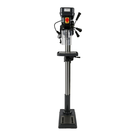
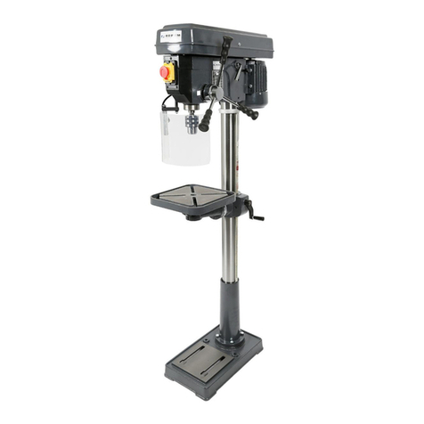
PEDESTAL DRILL PRESS
Specifications:
Motor: 240V 3/4HP
Number of Speeds: 16
Spindle Speeds: 162 - 3000rpm
Maximum Drilling Capacity: 16mm
Spindle Taper: MT2
Chuck: 16mm
Maximum Spindle Stroke: 78mm
Swing: 350mm
Maximum Distance from Spindle to Table:
443mm
Maximum Distance from Spindle to Base:
610mm
Diameter of Column: 73mm
Table Diameter: 290mm
Size of Base: 440 x 250mm
Overall Height: 1000mm
Weight: 48kg
Product Code: CH16NT

Aug-19 Product Code: CH16NT
Made in China to TQB Brands Pty Ltd specifications Page 2
Visit us at www.tqbbrands.com.au
WARNING
IMPORTANT: READ ALL INSTRUCTIONS BEFORE USE
WARNING
The instructions and warnings contained in this manual should be read and understood before using or operating this equipment.
Do not allow anyone to use or operate this equipment until they have read this manual and have developed a thorough
understanding of how this equipment works. Failure to observe any of the instructions contained in the manual could result in
severe personal injury to the user or bystanders, or cause damage to the equipment and property. Keep this manual in a
convenient and safe place for future reference.
Whilst every effort has been made to ensure accuracy of information contained in this manual, the TQB Brands Pty Ltd policy of
continuous improvement determines the right to make modifications without prior warning.
CONTENT
WARNING............................................................................................................................................................................................ 2
CONTENT............................................................................................................................................................................................. 2
STANDARD OPERATING PROCEDURE ................................................................................................................................................. 3
ASSEMBLY, OPERATION, PREVENTITIVE MAINTENANCE.................................................................................................................... 4
PARTS LIST......................................................................................................................................................................................... 10
PARTS DIAGRAM ............................................................................................................................................................................... 11
TROUBLESHOOTING.......................................................................................................................................................................... 12
WARRANTY ....................................................................................................................................................................................... 12

Aug-19 Product Code: CH16NT
Made in China to TQB Brands Pty Ltd specifications Page 3
Visit us at www.tqbbrands.com.au
STANDARD OPERATING PROCEDURE
DO NOT use this machine unless you have been trained and assessed to a competent level in its sate use and operation, and
have been given permission to use this
PRE-OPERATIONAL SAFETY CHECKS
1. Keep guards in place and in good working order
2. Keep drill press in good working order, follow lubricating and changing accessories instructions
3. Use recommended accessories only, failure to do so may damage the drill press and/or may risk injury
4. Remove adjusting keys & wrenches from the drill press before operating
5. Ensure the switch is in the OFF position before starting the drill press
6. Disconnect drill press before performing any maintenance
7. Keep work area clean, free from hazards and well lit.
8. Only use the drill press for its intended purpose.
9. Wear the correct PPE clothing.
10. Secure work using claims or vice where practical.
11. Do not overreach, keep proper footing and balance at all times while operating the drill press
12. Never leave drill press running unattended, always lock the “on – off” switch when not in use
13. Use only on hard level surfaces capable of sustaining the load.
14. Ensure that risk assessment has been read.
15. Check workspace and walkways to ensure no slip-hazards are present.
16. Faulty equipment must not be used. Immediately report suspect equipment.
OPERATIONAL SAFETY CHECKS
1. Never leave the machine running unattended.
2. Before making adjustments or before cleaning sward accumulations switch off and bring the machine to a complete
standstill.
3. Ensure that the work piece is securely held in a clamped work vice or clamped directly to the table.
4. Feed downwards at a sufficient rate to keep the drill cutting.
5. Feed with care as the drill breaks through the underside of the work.
6. Use a safe working posture (beware of hair catching).
HOUSEKEEPING
1. Switch off the machine.
2. Return all tooling and fixtures to the correct storage location.
3. Display a completed “Equipment in Use” notice if the machine is set up and/or in use but unattended.
4. Leave the machine and work are in a safe, clean and tidy state after job is completed.
5. Return surplus material to stock and dispose of waste material in an appropriate recycling or waste bin.
POTENTIAL HAZARDS
Hair/clothing entanglement –rotating spindle/drill
Flying swarf/chips
Eye injuries
Sharp edges and burrs
High noise levels when drilling some materials
Distracting operator
Removal or modification of safety devices
Using equipment with lapsed test tag
Safety glasses must be worn when operating this
equipment
Long loose hair must be contained when operating
this equipment
Safety footwear must be worn when operating
this equipment
Close fitting/protective clothing must be worn
when operating this equipment
Rings and jewellery must not be worn when
operating this equipment
Hearing protection must be worn where noise
levels are in excess of 85 dB(A) occupational
exposure limit
Gloves must not be worn when machine is
operating. Machine to be at standstill if gloves
required for manual operations.

Aug-19 Product Code: CH16NT
Made in China to TQB Brands Pty Ltd specifications Page 4
Visit us at www.tqbbrands.com.au
ASSEMBLY, OPERATION, PREVENTITIVE MAINTENANCE
1. FEATURES & MODELS
This "Borum Industrial Drill Press" delivers precision and power... and is designed to handle the demands of a professional
workshop environment. With a powerful long-life industrial quality 3/4 HP motor (that's fully enclosed in a durable metal
hood) double-wide spindle bearings and a precision spindle, this is one very reliable drilling machine.
Equipped with 16 drilling speeds from 162 to 3,000rpm and a 16mm drilling capacity this robust and user-friendly drill press
is ideal for a busy maintenance workshop or small production factory.
Perfect for fabricators looking for a drill press that's rugged enough to handle the demands of light and medium duty
production work and accurate enough to consistently deliver precise results.
2. ASSEMBLY
Fig 1. Column Assembly
1. Place column assembly on base and align holes on column support with
holes on base.
2. Secure the column with 4 bolts and washers (provided)
Fig 2. Table Bracket Installation
1. Remove collar and rack
2. Install table bracket and rack
Fig 3. Collar Installation
1. Install collar and tighten firmly
Fig 4. Bracket Installation
1. Install bracket, handle and clamp bolt
2. Tighten handle with attached set screw
Fig 5.
1. Install clamp bolt to tighten

Aug-19 Product Code: CH16NT
Made in China to TQB Brands Pty Ltd specifications Page 5
Visit us at www.tqbbrands.com.au
Fig 6.
1. Install table and clamp with bolt (provided)
Fig 7. Head Assembly
1. Position the head assembly over the column and slide into position.
Align head frame with table base
2. Fix set screws on right side of head to lock head into position, tighten
screws with allen key
Fig 8. Feeding Handle Installation
1. Screw knob on each feeding handle, install onto hub of pinion shaft
Fig 9. Arbor & Chuck Installation
1. Insert Arbor onto spindle. Pull feed handle down to press arbor into
position
2. Open chuck jaws completely by turning attached chuck key counter-
clockwise to the end.
3. Place a piece of wood on the table to protect chuck nose
Fig 10.
1. Install the chuck to the arbor and
tighten
Fig 11.
1. Install the knob and screw of upper
pulley cover
Ensure the drill press is firmly fixed in place to table or floor following assembly

Aug-19 Product Code: CH16NT
Made in China to TQB Brands Pty Ltd specifications Page 6
Visit us at www.tqbbrands.com.au
Table Adjustment
Fig 12. Height Adjustment
1. To adjust up or down, loosen the clamp bolt to adjust the table
the preferred position by turning the table bracket handle
Fig 13. Tilting Adjustment
1. Loosen the table bevel lock bolt with an adjustable wrench
2. Tilt the table to the preferred angle and re-tighten the bolt
Fig 14. Swing 360°
1. Loosen the clamp bolt and swing table to preferred position,
re-tighten clamp bolt
Fig 15 Feed Depth Adjustment
1. Depth control scale sleeve type
2. Loosen the clamp bolt and move to the preferred depth, re-
tighten the clamp bolt

Aug-19 Product Code: CH16NT
Made in China to TQB Brands Pty Ltd specifications Page 7
Visit us at www.tqbbrands.com.au
Speed Adjustment
Fig 16-1 Speed Adjustment
1. Open the pulley case and loosen the belt tension lock handle
2. Choose speed for drilling operation and move belt to correct
position for preferred speed
3. Push motor backward until moderate belt tension as required.
4. Re-tighten the lock handle. 16-1 & 16-2
Drilling Speed (Approximately)
Belt Tension Adjustment
Correct belt tension: Use 4.5kg’s of hand pressure on the belt as shown below. The distance is 1/2” (13mm) + 10%
Size
Diameter
Cast Steel
Tool Steel
Cast Iron
Mild Steel
Alum. & Copper
Cutting Speed
m/min
ft/min
m/min
ft/min
m/min
ft/min
m/min
ft/min
m/min
ft/min
12
40
18
60
24
80
30
100
60
200
mm
Inch
Cutting Speed Revolution Per Minute
2
1/16
1910
2445
2865
3665
3820
4890
4775
6110
9550
12225
3
1/8
1275
1220
1910
1835
2545
2445
3185
3055
6365
6110
5
3/16
765
815
1145
1220
1530
1630
1910
2035
3820
4075
6
¼
610
610
955
915
1275
1220
1590
1530
3180
3055
8
5/16
480
490
715
735
955
980
1195
1220
2390
2445
10
3/8
380
405
570
610
765
815
955
1020
1910
2035
11
7/16
350
350
520
525
700
700
870
870
1740
1745
13
1/2
300
305
440
460
590
610
735
765
1470
1530
16
5/8
240
245
360
365
480
490
600
610
1200
1220
19
3/4
190
205
285
305
380
405
480
510
955
1020

Aug-19 Product Code: CH16NT
Made in China to TQB Brands Pty Ltd specifications Page 8
Visit us at www.tqbbrands.com.au
Quill Spring Adjustment
Fig 17 Speed Adjustment
1. Move the stop nuts to the lowest position and lock into place
with a wrench to prevent quill dropping while tensioning spring
2. Place screwdriver in lower front notch (A) of spring cap (B) and
hold it in place while loosening and removing nuts.
3. Carefully turn screwdriver counter clockwise and engage next
notch
4. Tighten inner nut (C) with wrench. DO NOT overtighten as this
will restrict quill removal.
5. Move stop nuts to highest position and check tension while
turning feed handle. It there isn’t enough tension on spring,
repeat steps 2 –4.
6. Check quill while feeding for: Smooth and unrestricted
movement. If movement is too tight slightly loosen nuts until
unrestricted.
3. BEFORE USE
Prior to each use conduct a visual inspection checking for abnormal conditions, such as cracked welds, leaks, and damaged,
loose, or missing parts.
Caution: This drill press is intended for use only with drill bits. The use of other accessories may be hazardous.
Drill Speed: Factors that determine the best speed to use in any drill press operation are:
Type of material being worked on, size of hole, type of drill or cutter and quality of cut desired. The smaller
the drill bit, the greater the required RPM. For softer materials, the speed should be higher than firmer
material.
Drill Metal: Use clamps to hold work in place when drilling metal. DO NOT hold with hand. The flutes of the drill may
seize the work at any time, especially when breaking through stock, causing the work piece to spin.
Clamp: The work must be clamped firmly while drilling: Any tilting, twisting, or shifting results not only in a rough
hole, but also increases drill bit breakage. For flat work, lay the piece on a wooden base and clamp firmly
down against the table to prevent the work piece from turning. If the piece is of irregular shape and cannot
be laid flat on the table, is should be securely blocked and clamped.
Chuck: The chuck should be securely fastened to the spindle. Remove the chuck after adjustment. Only use the
chuck key provided by the manufacturer. This chuck key is spring loaded to prevent the chuck key from
remaining in the chuck during operation of the drill.
Fixing: Fasten base of drill press to the floor before using to ensure no tipping, sliding of drill press.
The set screws of the head frame should be secured tightly before using this machine.
Power: When mounting the motor, ensure the power is disconnected. Connect to power supply protected by a
circuit breaker.
Transportation: Lifting by Forklift;
1. If lifting equipment isn’t available, use 1ton capacity forklift under the machine base to locate to
position
2. To move the drill press safely, place the forks of the forklift at the rear of the drill press –the drill press
must only be moved while on a pallet.
3. Keep balance of drill press on pallet while moving with forklift.

Aug-19 Product Code: CH16NT
Made in China to TQB Brands Pty Ltd specifications Page 9
Visit us at www.tqbbrands.com.au
4. OPERATION
Fig 18 Installing Drills
1. Insert drill into chuck jaws approx. 1” (25.4mm) long. When using a
small drill do not insert too far for the jaws to tough the flutes of the
drill. Make sure that the drill is centred in the chuck before tightening
the chuck with the key.
Fig 19 Workpiece Positioning
1. Always place a piece of wood (or plywood) on the table to prevent
“splintering” and/or burrs on the underside of the workpiece as the
drill breaks through. Position the wood so that it is in contact with the
left side of the column
For small pieces that cannot be clamped to the table, use a drill press vice. The vice must be clamped or bolted to the
table.
5. INSPECTION
Prior to each use conduct a visual inspection checking for abnormal conditions, such as cracked welds, leaks, and
damaged, loose, or missing parts.
The drill press shall always be maintained in accordance with the maintenance instructions. No alterations or
modifications shall be made to this drill press.
Inspections shall be performed in accordance with this owner’s manual.
The drill press must be inspected immediately if it is believed to have been subjected to abnormal load or shock.
Owners and /or operators should be aware that repair of this product may require specialised equipment and knowledge
(refer to maintenance section).
6. STORAGE
This drill press should always be stored in a dry location on a level surface with the power switched off.
7. MAINTENANCE
DISCONNECT Drill Press before performing any maintenance
FREQUENTLY blow out any dust that may accumulate inside the motor
APPLY a coat of automobile type wax or similar to the table and column to keep surface clean
LUBRICATION; all the ball bearings are packed with grease at the factory. They require no further lubrication
PERIODICALLY lubricate the gear and rack table elevation mechanism, the splines (grooves) in the spindle and the rack
(teeth on the quill)
Only use replacement parts that are approved by the manufacturer.
Regularly clean all surfaces and maintain all labels and warnings.
8. SERVICE & REPAIR
Any Borum Industrial Drill Press found damaged in any way, or found to be worn or operates abnormally should be removed
from service until repaired by an authorised service agent. Owners and / or operators should be aware that repair of this
product may require specialised equipment and knowledge. Only authorised parts, labels, decals shall be used on this
equipment. Annual inspection of the drill press is recommended and can be made by an authorised repair facility to ensure
that your equipment is in optimum condition and that the equipment has the correct decals and safety labels specified by the
manufacturer.

Aug-19 Product Code: CH16NT
Made in China to TQB Brands Pty Ltd specifications Page 10
Visit us at www.tqbbrands.com.au
PARTS LIST
Part #
Description
QTY
Part #
Description
QTY
Part #
Description
QTY
1
Base
1
36
Clamp
2
71
Nut
1
2
Base Flange
1
37
Screw
2
72
Table
1
3
Washer
4
40
Motor Label
1
81
Washer
1
4
Screw
4
41
Motor
1
82
Screw
1
5
Column
1
42
Set Screw
1
83
Key
1
6
Rack
1
43
Motor Pulley
1
84
Chuck
1
7
Screw
1
44
V-Belt
1
85
Clamp Bolt
1
8
Sleeve
1
45
Screw
2
86
Screw
1
9
Shifting Rod
1
47
Screw
4
87
Zero Mark
1
10
Set Screw
1
49
Screw
2
88
Table Arm
1
11
Clamp Bolt
1
50
Screw
1
89
Table Bracket
2
12
Shaft
1
51
Knob
1
90
Rivet
1
13
Screw
1
52
Pulley Guard (Upper)
1
92
Gear
1
14
Rack Collar
1
53
Screw
1
93
Worm
1
15
Scale Sleeve
1
54
Speed Chart
1
94
Angle Scale
1
16
Rivet
1
55
Switch
1
95
Spindle
1
17
Pin
2
56
Pulley Guard (Lower)
1
96
Arbor
1
18
Knobs
3
57
Nut
1
97
Wedge
1
19
Feed Handles
3
58
Spindle Pulley
1
98
V Belt
1
20
Handle Base
1
59
Driving Taper Sleeve
1
99
Head Frame
1
21
Feed Pinion
1
60
“C” Snap Ring
2
100
Lamp Receptacle
1
22
Scale
2
61
Bearing
2
102
Lock Ring, Shaft
1
23
Set Screw
1
63
Screw
2
103
Lock Ring, Pulley
1
25
Set Screw
1
64
Rivet
4
104
Bearings
1
26
Screw Knob
1
65
Switch Plate
1
105
Central Pulley
1
27
Cord & Plug
1
66
Spring
1
106
Shaft
1
28
Spring
1
67
Cap
1
108
Shaft
1
29
Rod
1
68
Nuts
1
109
Quill
1
34
Strip Relief
2
69
Name Plate
1
110
Bearing
1
35
Cord
1
70
Screw
1
111
Ring
1

Aug-19 Product Code: CH16NT
Made in China to TQB Brands Pty Ltd specifications Page 11
Visit us at www.tqbbrands.com.au
PARTS DIAGRAM

Aug-19 Product Code: CH16NT
Made in China to TQB Brands Pty Ltd specifications Page 12
Visit us at www.tqbbrands.com.au
TROUBLESHOOTING
PROBLEM
POSSIBLE CAUSE
REMEDY
Noisy Operation
Incorrect belt tension
Dry spindle
Loose pulley
Loose belt
Bad bearing
Adjust tension
Remove spindle/quill assembly & lubricate
Tighten pulley
Adjust belt tension
Replace bearing
Excessive drill wobble
Loose chuck
Worn spindle shaft or bearing
Bad chuck
Tighten by pressing chuck down against table
Replace spindle shaft or bearing
Replace chuck
Motor won’t start
Power supply
Motor connection
Switch connections
Motor windings burnt
Bad switch
Check power cord
Check motor connections
Check switch connections
Replace motor
Replace switch
Drill binds in workpiece
Excessive pressure on feed handle
Loose belt
Loose drill
Speed too fast
Apply less pressure
Check belt tension
Tighten drill with key
Change speed
Drill burns or smokes
Incorrect speed –reduce RPM
Fillings caught in drill bit
Poor drilling
Incorrect feed pressure
Refer to RPM sheet
Clean drill bit
Sharpen drill bit or replace drill bit
Apply less pressure
Table difficult to raise
Needs lubrication
Bent rack
Table lock too tight
Lubricate with a light oil
Straighten rack
Loosen clamp
WARRANTY
BORUM Industrial products have been carefully tested and inspected before shipment and are guaranteed to be free from
defective materials and workmanship for a period of 12 months from the date of purchase except where tools are hired out when
the guarantee period is ninety days from the date of purchase.
Should this piece of equipment develop any fault, please return the complete tool to your nearest authorised warranty repair
agent or contact TQB Brands Pty Ltd Warranty team –warranty@tqbbrands.com.au.
If upon inspection it is found that the fault occurring is due to defective materials or workmanship, repairs will be carried out free
of charge. This guarantee does not apply to normal wear and tear, nor does it cover any damage caused by misuse, careless or
unsafe handling, alterations, accident, or repairs attempted or made by any personnel other than the authorised TQB Brands Pty
Ltd repair agent.
This guarantee applies in lieu of any other guarantee expressed or implied and variations of its terms are not authorised.
Your TQB Brands Pty Ltd guarantee is not effective unless you can produce upon request a dated receipt or invoice to verify your
proof of purchase within the 12month period.
Consumer Guarantee
Our goods come with a guarantee that cannot be excluded under the Australian Consumer Law. You are entitled to a replacement
or refund for a major failure and compensation for any other reasonably foreseeable loss or damage. You are also entitled to have
the goods repaired or replaced if the goods fail to be of acceptable quality and the failure does not amount to a major failure.
Table of contents
Other Borum Power Tools manuals

