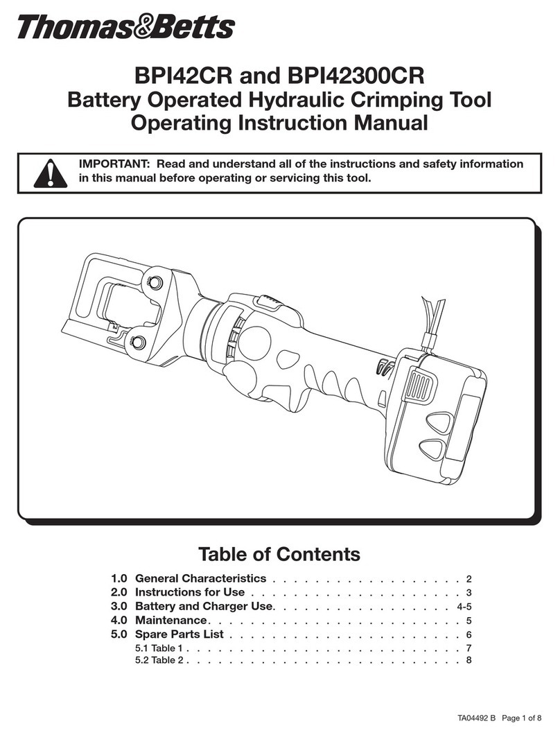
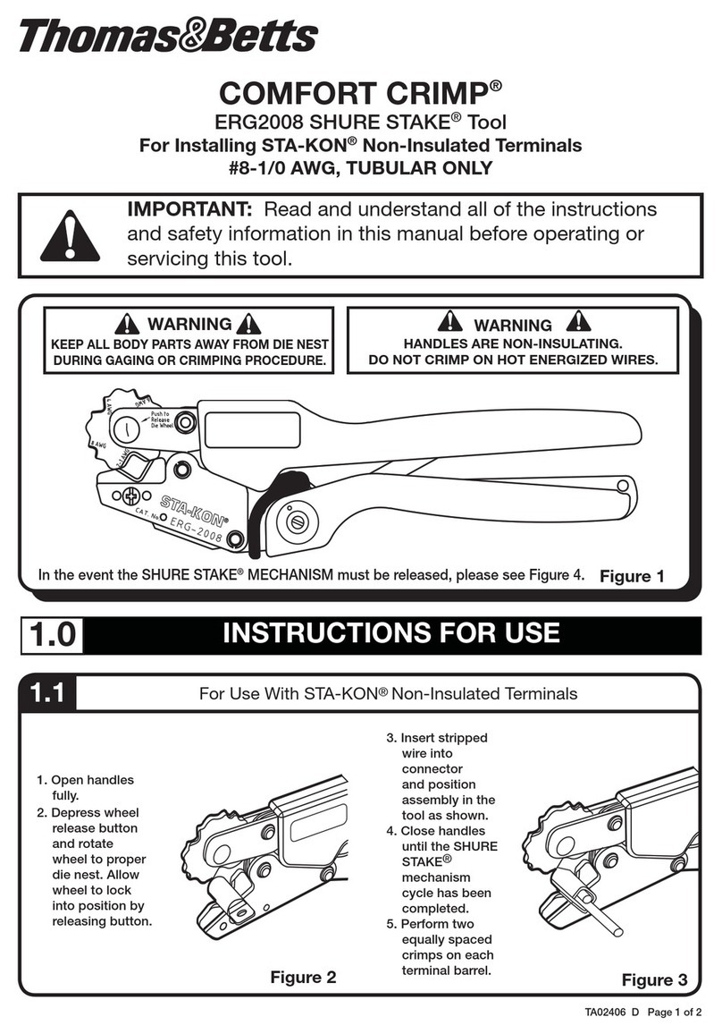
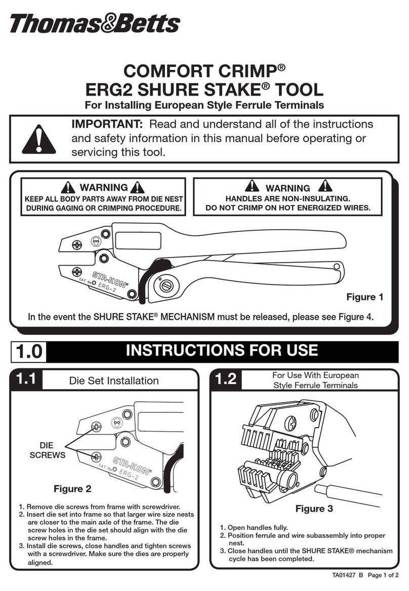
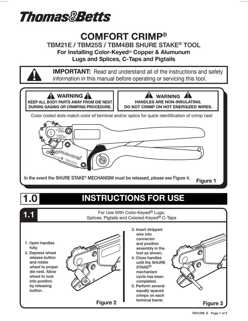
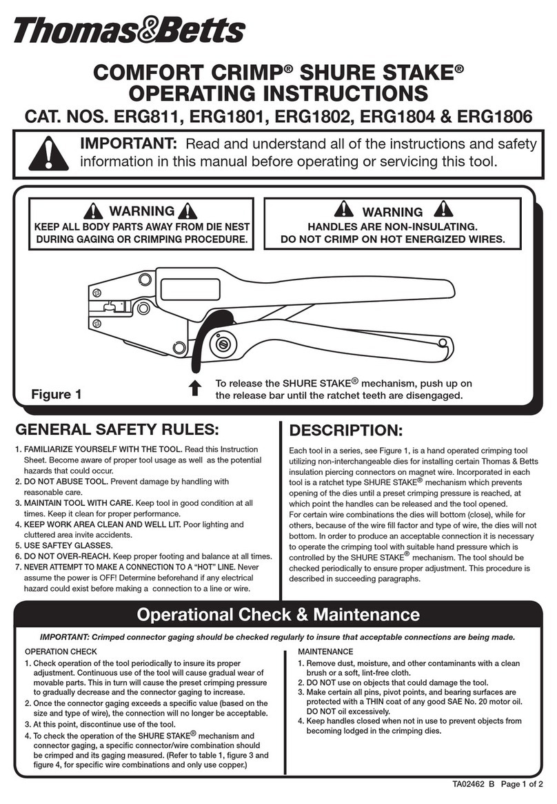
Thomas&Betts BAT22-6 User manual

Read and understand all of the instructions
and safety information in this manual before
operating or servicing this tool.
BAT22-6
Battery-Powered Crimping Tool
1.0 General Information . . . . . . . . . . . . . . . . . . . . 2
1.1 Description . . . . . . . . . . . . . . . . . . . . . . . . 2
1.2 Safety . . . . . . . . . . . . . . . . . . . . . . . . . . 2
1.3 Purpose of this manual . . . . . . . . . . . . . . . . . . . 2
1.4 Specification . . . . . . . . . . . . . . . . . . . . . . . 2
2.0 Operation . . . . . . . . . . . . . . . . . . . . . . . . . 3
2.1 Charging the battery . . . . . . . . . . . . . . . . . . . . 3
2.2 LED Display . . . . . . . . . . . . . . . . . . . . . . . . 3
2.3 Preparing cable . . . . . . . . . . . . . . . . . . . . . . 3
2.4 Installing dies . . . . . . . . . . . . . . . . . . . . . . . 3
2.5 Crimping cable . . . . . . . . . . . . . . . . . . . . . . 4
3.0 Maintenance. . . . . . . . . . . . . . . . . . . . . . . . 4
3.1 Each operating day . . . . . . . . . . . . . . . . . . . . . 4
4.0 Troubleshooting . . . . . . . . . . . . . . . . . . . . . . 4
4.1 Problems & Remedies. . . . . . . . . . . . . . . . . . . . 4
5.0 Battery Maintenance. . . . . . . . . . . . . . . . . . . . 5
5.1 Battery maintenance warning and cautions . . . . . . . . . . . 5
6.0 Maintenance. . . . . . . . . . . . . . . . . . . . . . . . 5
6.1 Main Assembly . . . . . . . . . . . . . . . . . . . . . . 5
6.2 Pump housing unit, relief valve unit and piston pump assembly . . . 6
6.3 Motor Assembly . . . . . . . . . . . . . . . . . . . . . . 6
7.0 Parts List . . . . . . . . . . . . . . . . . . . . . . . . . 7
8.0 Calibration Verification . . . . . . . . . . . . . . . . . . . 8
Table of Contents
TA02712 G
Page 1 of 8
Tel:
+44
(0)117 977 4647
Fax: +44 (0)117 977 5582
Email: exports@thorneandderrick.co.uk
Website: www.cablejoints.co.uk
www.thorneanderrick.co.uk

1.2 SAFETY
1.0
1.1 DESCRIPTION
1.3 PURPOSE OF THIS MANUAL
1.4 SPECIFICATION
TA02712 G
Page 2 of 8
The BAT22-6 Battery-powered Crimping Tool is a
hand-held, self-contained crimping tool intended
to crimp terminals, splices, and disconnects on 22
AWG through 6 AWG wires using appropriate dies.
Safety is essential in use and maintenance of Thomas
& Betts tools and equipment. This manual and any
markings on the tool provide information for avoiding
hazards and unsafe practices related to the use of this
tool. Observe all of the safety information provided.
This manual is intended to familiarize all personnel
with the safe operation and maintenance procedures
for the following Thomas & Betts tool:
BAT22-6 Battery-powered Crimping Tool
Keep this manual available to all personnel.
Replacement manuals are available upon request at
no charge.
Crimping Dies
(Not included.
Order separately,
See Table 1,
step 2.3)
Retract Button
Battery Lock
Battery Cartridge
Trigger
Crimping Tool
Length .................................................14” (356 mm)
Width................................................ 2-3/8” (60 mm)
Depth ............................................... 3-1/8” (80 mm)
Mass/Weight (with battery) ...............2.8 lb. (1.3 kg)
Sound Level.............................75 dB (A) at 1 meter
Vibration................................................... < 2.5 m/s2
Hydraulic Oil ............................... Shell Tellus®* T 15
Crimping Capacities
Maximum Crimping Force..............1.5 tons (13 kN)
Average Crimping Time...........................2 seconds
Average Crimps per Charge ..... approximately 150
Battery
Charging Voltage ............................................. 9.6 V
Charging Time ....................................... 40 minutes
All specifications are nominal and may change
as design improvements occur. Thomas & Betts
shall not be liable for damages resulting from
misapplication or misuse of its product.
*Tellus is a registered trademark of Shell Oil Company
Crimping Head
13mm Die Pins
18mm Die Pins
FIGURE 1
Ram
LED Display
GENERAL INFORMATION

2.3 PREPARING CABLE
BAT22-6 Die Ordering Information
CAT. NO. DESCRIPTION
DIE2001 Insulated 22-10 AWG Sta-Kon
®
Terminals
DIE2002 Non-insulated 22-10 AWG Sta-Kon
®
and Spec-Kon
®
Terminals
DIE2005 Non-insulated 16-6 AWG Sta-Kon
®
and Spec-Kon
®
Terminals
DIE2007 Insulated 8-6 AWG Sta-Kon
®
Terminals
DIE2500 Insulated 22-10 AWG Spec-Kon
®
Terminals
TABLE 1
2.4
Signal Duration When it occurs What it means
a few seconds of
flashing battery insertion self check - O.K.
glowing for 20 seconds after crimp battery discharged
flashing for 20 seconds
(2 Hz) after crimp time for inspection and
preventive maintenance
20 sec. glowing and
flashing intermittently after crimp
battery discharged - time for
inspection and preventive
maintenance
CAUTION
It does not matter in which location the indentor or nest
half of the die set is installed, either crimping head or
ram. However, it is very important that the largest nest
be positioned away from the open side of the crimping
head, closest to the head itself. Failure to do so will
result in premature head failure.
2.0
WARNING
2.1 CHARGING THE BATTERY
Read all instructions supplied with the battery charger.
OPERATION
TA02712 G
Page 3 of 8
Follow the lug manufacturer’s instructions for
appropriate cable strip length.
ELECTRIC SHOCK HAzARD: This tool is not
insulated. When using this unit near energized
electrical lines, use proper personal protective
equipment. Failure to observe this warning could
result in severe injury or death.
PINCH POINTS: Keep hands away from the crimping
head when crimping. Failure to observe this warning
could result in severe injury.
EYE PROTECTION: Wear eye protection when
operating or servicing this tool. Failure to wear eye
protection could result in serious eye injury from flying
debris or hydraulic oil.
INSTALLING DIES
1. Select the proper die set for the intended crimping
operation, see Table 1.
2. Remove screw, washer, and die mounting pins from the
crimping head.
3. Extend the ram partially by momentarily pulling the
trigger to access the screw, washer, and pins in the ram,
and remove.
4. Insert one die half into the partially extended ram.
Install the 13 mm pins**, screw and washer through the
ram mounting holes and the die half. Tighten screw
snugly. Retract ram fully by depressing retract button.
5. Insert remaining die half into the crimping head, and
install with 18 mm pins**, screw and washer. Tighten
screw snugly.
** DIE2001, DIE2500 do not use die mounting pins.
When installing the dies, proceed as described above but
do not tighten screws fully. After die set is in place, ensure
dies are properly aligned and extend the ram until the dies
engage under some pressure.
Tighten screws snugly.
CAUTION
• Donotoperatethetoolwithoutdies.Damagetotheramorcrimpingheadcanresult.
• Donotoperatewiththecrimpingheadopen.Damagetotheramorsealscanresult.
• Thistoolisnotdesignedforcontinuoususe.After100crimpingcycles,allowthecrimpingtooltocoolfor15minutes.
•Donotplacethetoolinavise.Thecrimpingtoolisdesignedforhand-heldoperation.
• Thistoolmaybeusedindamporwetenvironments;however,werecommendair-dryingthetoolbeforeuseifitbecomessoaked.
• Usethistoolformanufacturer’sintendedpurposeonly.
FAILURE TO OBSERVE THESE PRECAUTIONS MAY RESULT IN INJURY OR PROPERTY DAMAGE.
WARNING
An incomplete crimp can cause a fire.
•Useproperdie,connector,andcablecombinations.
Improper combinations can result in an incomplete
crimp.
•Thereliefvalvewillsoundtoindicateacompletedcrimp.
Ifyoudonothearthesoundofthereliefvalve,thecrimp
is not complete.
FAILURE TO OBSERVE THESE WARNINGS COULD
RESULT IN SEVERE INJURY OR DEATH.
LED DISPLAY
2.2
This tool is equiped with a special circuit board incorporating
several important features to inform the user about the current
status of the unit. The LED signals in the following cases:
2.5 CRIMPING CABLE
1. Insert the properly assembled connector into the crimping
head.
2. Pull the trigger to make the crimp.
3. Hold the trigger down until the crimping tool achieves
pressure relief, which is accompanied by an audible “pop”.
4. The crimping tool returns automatically.
5. Position the crimping tool for the next crimp. Repeat
Steps 2 and 3 for the next crimp (see Figure 1).
Sta-Kon®Terminals
One crimp required.
Sta-Kon®Splice
Two crimps required, one
crimp on each side.
Crimp
Non Insulated
Insulated
Non Insulated
Insulated
FIGURE 2
Crimp
Crimp Crimp
Crimp
Crimp
NOTE: If it is necessary to retract the ram before a crimping
cycle is complete, push the retract button which will result in
the complete retraction of the ram.
Problem Probable Cause Probable Remedy
Tool is inoperative.
Dirt, Contaminants, etc., in ram area of tool. Clean tool.
Crimping tool battery contacts damaged. Reform contacts.
Tool components worn or damaged. Return tool to an authorized Thomas & Betts service center.
Battery contacts dirty Clean contacts with nonflammable contact cleaner or pencil eraser
Battery discharged Charge or replace battery
Dies stop during operation.
Oil level is low. Return to an authorized T&B Tool Service Center.
Air in hydraulic system. Pull trigger and hold retract button simultaneously. Hold for approximately 10
seconds.
LED glows for 20 seconds. Battery charge low. Charge or replace battery.
Tool loses oil. Damaged internal seal. Return tool to an authorized T&B Tool Service Center.
For parts and service, contact Thomas & Betts Tool Service center at 1-800-284-TOOL (8665).
MAINTENANCE
3.0
3.1 EACH OPERATING DAY
BEFORE USE:
1. Inspect dies for wear or damage such as cracks,
gouges, or chips.
2. Inspect the tool for damage or leaks. If damage
is detected, return the tool to an authorized
Thomas & Betts service center for inspection.
AFTER USE:
1. Wipe all tool surfaces clean with a damp cloth
and mild detergent.
TA02712 G
Page 4 of 8
Skininjectionhazard:
Donotusehandstocheckforoilleaks.
Highpressureoileasilypuncturesskin
causingseriousinjury.Ifinjured,seek
medicalhelpimmediatelytoremoveoil.
WARNING
2. Fully retract the ram. Place the tool in the
carrying case. Store in a cool, dry place.
3. Charge the battery.
MONTHLY:
Thoroughly clean all surfaces.
ANNUALLYORAFTER10,000CRIMPS:
Return the tool to an authorized Thomas & Betts
service center for inspection.
Donotusesolventsorammable
cleaners to clean the crimping tool body.
Solventscouldignite,causingserious
injuryorpropertydamage.
WARNING
TROUBLESHOOTING
4.0
4.1 PROBLEMS & REMEDIES
Keep hands away from the crimping
headwhencrimping.Failuretoobserve
thiswarningcouldresultinsevereinjury.
WARNING

Donotallowconductiveobjectstocontactthebattery
terminals.
• Donotimmersethebatteriesinliquid.Liquidmay
create a short circuit and damage the battery.
Ifbatteriesareimmersed,contactyourservice
center for proper handling.
• Donotplacethebatteryintoapocket,toolpouch,
ortoolboxwithconductiveobjects.Conductive
objectsmaycreateashortcircuitanddamagethe
battery.
• Donotplaceabatteryonmoistgroundorgrass.
Moisture may create a short circuit and damage
the battery.
Failuretoobservetheseprecautionsmayresultin
injuryorpropertydamage.
CAUTION
TA02712 G
Page 5 of 8
BATTERY MAINTENANCE WARNINGS AND CAUTIONS
BATTERY MAINTENANCE
5.0
5.1
Donotdisposeofbatteriesinare.Theywillvent
fumes and may explode.
Failuretoobservethiswarningcouldresultinsevere
injuryfromharmfulfumesorburnsfromyingdebris.
WARNING
• Donotstorethebatteryatmorethan60ºC(140ºF).
Damage to the battery can result.
• Donotuseanothermanufacturer’scharger.Other
Manufacturer’schargersmayoverchargeand
damage the battery
• Donotattempttoopenthebattery.Itcontainsno
user-serviceableparts.
Failuretoobservetheseprecautionsmayresultin
injuryorpropertydamage.
CAUTION
ILLUSTRATIONS
6.0
MAIN ASSEMBLY
6.1
100
103 101
17
97
99
103
102
100
98
95 94
93
92
91
90
7
148
142
140
141
13
140
145
144
143
10 11
12
15
146
14
141
147
16

32
33
34
35
36 37
38
39
70
71
72
73
74
76
75
78
79
TA02712 G
Page 6 of 8
PUMPHOUSINGUNIT,RELIEFVALVEUNIT,ANDPISTONPUMPASSY.
6.2
56
50
54
53
52
55 50
51
123
122
121
120
30
31
MOTOR ASSEMBLY
6.3

7.0 PARTS LIST
TA02712 G
Page 7 of 8
KEY PART NO. DESCRIPTION QTY
7* 501 2005.0 Bushing with seal 1
10 500 1928.7 Lever, relief valve 1
11 500 1929.5 Screw 1
12 520 2664.0 Switch 1
13 TA02638 Decal, identification 1
14 TA02637 Decal, identification 1
15 Decal, warning 1
16 TA02655 Decal, specification 1
17 Decal, pinch hazard 1
5001892.2 Relief valve unit (includes 30 – 39)
30* 500 5862.2 Seal 1
31 500 1955.4 Valve seat 1
32 500 1946.5 Needle Valve 1
33 500 1954.6 Plunger 1
34 501 0377.6 Spring 1
35 500 7015.0 Lock washer 2
36* 500 6370.7 O-ring 1
37* 500 1906.6 O-ring 1
38 500 1952.0 Pressure relief 1
39 501 0914.6 Screw 1
500 1894.9 Pump housing unit (includes 50 – 56)
50* 500 1972.4 Clamp 2
51 500 1902.3 Screw 1
52 501 0916.2 Threaded bushing 1
53 500 1957.0 Pump block 1
54 501 0930.8 Threaded bushing 1
55 501 0931.6 Screen 1
56 500 1944.9 Reservoir 1
500 1895.7 Motor assembly (includes 70 – 79)
70 500 1965.1 Retaining ring 1
71 500 1958.9 Pin 1
72 500 1961.9 Motor cap 1
73 500 1953.8 Disc housing 1
74 500 1962.7 Disc 2
75 500 1979.1 Screw 2
76 500 1974.0 Gear lube, 1.5 g 1
78 501 0933.2 Motor adapter 1
79 500 1896.5 Motor, electric 1
KEY PART NO. DESCRIPTION QTY
500 5111.3 Head unit (includes 90 – 30)
90 500 1922.8 Bolt, shoulder 1
91 500 1915.5 Cap 1
92 500 1916.3 Compression spring 1
93 500 1912.0 Compression spring 1
94 500 1911.2 Washer 1
95 500 5113.0 Crimping head 1
97 500 5115.6 Die holder 1
98 500 1929.5 Screw 1
99 Pin, 13 mm 2
100 Pin, 18 mm 2
101 Screw, M4 x 20 1
102 Screw, M4 x 16 1
103 Washer 2
500 1899.0 Piston pump assembly (includes 120 – 123)
120 500 1931.7 Piston pump 1
121 500 1901.5 Spring 1
122 500 1930.9 Piston pump housing 1
123* 500 0369.5 Piston seal 1
500 5116.4 Housing unit, blue (includes 140 – 148)
140 500 4207.6 Screw 4
141 500 1976.7 Screw 2
142 500 4396.0 Compression spring, DA5.5 x L14.0 1
143 500 1934.1 Link, trigger 1
144 Lever, battery release 1
145 Housing half 1
146 Housing half 1
147 Button, relief valve 1
148 Cover, trigger 1
* 500 2724.7 Seal kit (includes items marked with an
asterisk)
500 1965.1 Die pin kit (includes 99 – 103)
500 5126.1 Pin
501 1834.0 Decal kit (includes 13 – 17)
500 5117.2 Case with inserts
500 5121.0 Decal, case
520 2663.8 9.6 V battery
520 2770.0 12 V charger 120 VAC

FOR PARTS OR SERVICE,
CONTACT TOOL SERVICE CENTER AT 1-800-284-TOOL (8665)
Thomas & Betts Corporation
Memphis, Tennessee
www.tnb.com
© 2013 Thomas & Betts Corporation. All Rights Reserved.
TA02712 G
Page 8 of 8
WARNING
This tool is equipped with the
SHURE STAKE
®
full stroke compelling mechanism.
Keep fingers clear of die nest during gaging
procedure.
8.1 VISUAL INSPECTION
Tool must be free of cracks, sharp edges and other
obvious imperfections that may affect performance
of the tool. Nest area must be free of burrs, dents or
scratches.
WARRANTY: Thomas & Betts sells this product with the understanding that the user will perform all necessary tests to determine the suitability of this product for the
user’s intended application. Thomas & Betts warrants that this product will be free from defects in materials and workmanship for the period stated on the enclosed
warranty card. Upon prompt notification of any warranted defect, Thomas & Betts will, at its option, repair or replace the defective product. Misuse, misapplication or
modification of Thomas & Betts products immediately voids all warranties.
Limitations and Exclusions: THE ABOVE WARRANTY IS THE SOLE WARRANTY CONCERNING THIS PRODUCT, AND IS IN LIEU OF ALL OTHER WARRANTIES
EXPRESS OR IMPLIED, INCLUDING BUT NOT LIMITED TO ANY IMPLIED WARRANTY OF MERCHANTABILITY OR FITNESS FOR A PARTICULAR PURPOSE,
WHICH ARE SPECIFICALLY DISCLAIMED. LIABILITY FOR BREACH OF THE ABOVE WARRANTY IS LIMITED TO COST OF REPAIR OR REPLACEMENT OF THE
PRODUCT, AND UNDER NO CIRCUMSTANCES WILL THOMAS & BETTS BE LIABLE FOR ANY INDIRECT, SPECIAL, INCIDENTAL OR CONSEQUENTIAL DAMAGES.
NOTE: Calibration verification procedure should be performed whenever the tool is damaged or damage is suspected.
TABLE 3
DIE2002 GAGING REQUIREMENTS
NEST GAGING
MIN. – MAX. WIRE SIZE
A .062 – .067 #22 – #18 AWG
B .084 – .089 #16 – #14 AWG
C .110 – .115 #12 – #10 AWG
TABLE 2
DIE2001 GAGING REQUIREMENTS
NEST GAGING
MIN. – MAX. WIRE SIZE
RED .100 – .103 #22 – #18 AWG
BLUE .117 – .120 #16 – #14 AWG
YELLOW .149 – .152 #12 – #10 AWG
TABLE 4
DIE2007 GAGING REQUIREMENTS
NEST GAGING
MIN. – MAX. WIRE SIZE
RED .190 – .196 #8 AWG
BLUE .212 – .218 #6 AWG
TABLE 5
DIE2500 GAGING REQUIREMENTS
NEST GAGING
MIN. – MAX. WIRE SIZE
RED .080 – .088 #22 – #16 AWG
BLUE .091 – .099 #16 – #14 AWG
YELLOW .119 – .127 #12 – #10 AWG
TABLE 6
DIE2005 GAGING REQUIREMENTS
NEST GAGING
MIN. – MAX. WIRE SIZE
B .083 – .089 #16 – #14 AWG
C .118 – .124 #12 – #10 AWG
D-E .176 – .181 #8 – #6 AWG
8.0 CALIBRATION VERIFICATION
8.2 GAGING PROCEDURE
NOTE: Wipe die nest before gaging.
1. Cycle tool until dies bottom.
2. Using gage pins, insure that each nest meets the
gaging requirements as specified in TABLE 2, 3,
4, 5 or 6 per the corresponding die.
UPON SUCCESSFUL COMPLETION OF
THE ABOVE PROCEDURE, THE PREVIOUS
CALIBRATION OF THE TOOL IS VERIFIED.
NOTICE: If tool fails any of the above tests, do
not attempt repair or adjustment. Call the nearest
Thomas & Betts Tool Service Center to arrange for repair
service. Any change, modification or alteration of the
tool or use by the customer in a manner other than as
specified by Thomas & Betts shall void all warranties
express or implied and the customer shall, therefore,
assume all liability for any damage or injury caused by
said change, modified or altered tool or improper usage
or such tool.
Tel:
+44
(0)117 977 4647
Fax: +44 (0)117 977 5582
Email: exports@thorneandderrick.co.uk
Website: www.cablejoints.co.uk
www.thorneanderrick.co.uk
Table of contents
Other Thomas&Betts Power Tools manuals

Thomas&Betts
Thomas&Betts BPI42CR Instruction Manual

Thomas&Betts
Thomas&Betts COMFORT CRIMP TBM21E Use and care manual

Thomas&Betts
Thomas&Betts BCT840 Reference guide

Thomas&Betts
Thomas&Betts COMFORT CRIMP TBM21E User manual

Thomas&Betts
Thomas&Betts Sta-Kon PAIR22-6 User manual

Thomas&Betts
Thomas&Betts COMFORT CRIMP SHURE STAKE ERG2008 User manual

Thomas&Betts
Thomas&Betts COMFORT CRIMP SHURE STAKE ERG2 User manual

Thomas&Betts
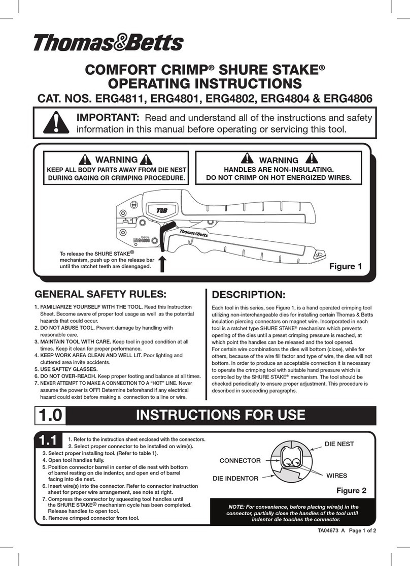
Thomas&Betts COMFORT CRIMP SHURE STAKE ERG4811 User manual

Thomas&Betts
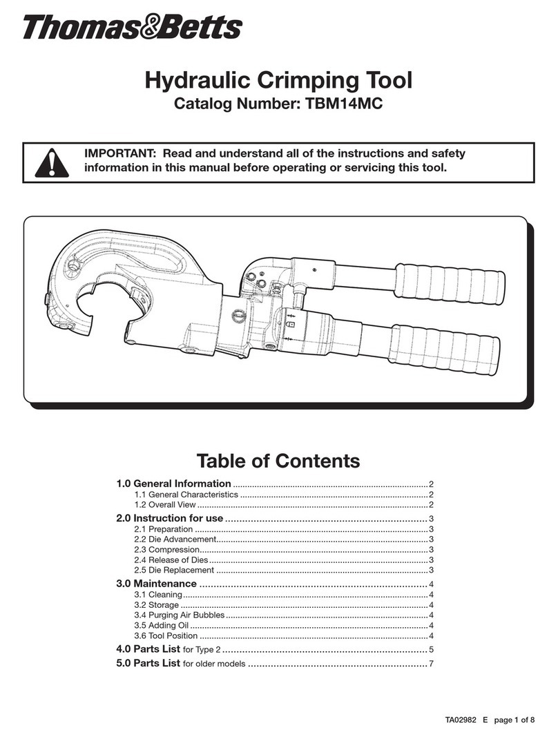
Thomas&Betts TBM14MC User manual

Thomas&Betts
Thomas&Betts Stakon COMFORT CRIMP ERG4005 User manual