Bosch Automation CPS21_3 User manual

Antriebs- und Steuerungstechnik
CPS21_3 / CPS21_4
Interface Conditions
Industrial PC
Edition 103

Industrial PC
CPS21_3 / CPS21_4
Interface Conditions
1070 073 825-103 (02.04) GB
E1999 – 2002
by Bosch Rexroth AG, Erbach / Germany
All rights reserved, including applications for protective rights.
Reproduction or distribution by any means subject to our prior written permission.
Discretionary charge 6.–

Contents V
1070 073 825-103 (02.04) GB
Contents
Page
1 Safety Instructions 1–1. . . . . . . . . . . . . . . . . . . . . . . . . . . .
1.1 Proper use 1–1. . . . . . . . . . . . . . . . . . . . . . . . . . . . . . . . . . . . . . . . . . . . .
1.2 Qualified personnel 1–3. . . . . . . . . . . . . . . . . . . . . . . . . . . . . . . . . . . . . .
1.3 Safety markings on products 1–4. . . . . . . . . . . . . . . . . . . . . . . . . . . . . .
1.4 Safety instructions in this manual 1–5. . . . . . . . . . . . . . . . . . . . . . . . . .
1.5 Safety instructions for the product described 1–6. . . . . . . . . . . . . . .
1.6 Documentation, software release and trademarks 1–8. . . . . . . . . . .
2 System Overview CPS21_3 / CPS21_4 2–1. . . . . . . . . .
2.1 Components 2–1. . . . . . . . . . . . . . . . . . . . . . . . . . . . . . . . . . . . . . . . . . . .
2.2 Technical Data 2–5. . . . . . . . . . . . . . . . . . . . . . . . . . . . . . . . . . . . . . . . . .
2.3 Software 2–6. . . . . . . . . . . . . . . . . . . . . . . . . . . . . . . . . . . . . . . . . . . . . . .
2.4 Expansion Cards 2–7. . . . . . . . . . . . . . . . . . . . . . . . . . . . . . . . . . . . . . . .
2.4.1 BIOS Setup 2–8. . . . . . . . . . . . . . . . . . . . . . . . . . . . . . . . . . . . . . . . . . . .
2.5 Rechargeable Battery Pack 2–9. . . . . . . . . . . . . . . . . . . . . . . . . . . . . . .
2.6 Operating Conditions 2–11. . . . . . . . . . . . . . . . . . . . . . . . . . . . . . . . . . . .
2.7 Applicable Standards 2–12. . . . . . . . . . . . . . . . . . . . . . . . . . . . . . . . . . . .
3 Safety Functions 3–1. . . . . . . . . . . . . . . . . . . . . . . . . . . . . .
3.1 Temperature Monitoring 3–1. . . . . . . . . . . . . . . . . . . . . . . . . . . . . . . . . .
3.2 Function of Uninterruptible Power Supply (UPS) 3–2. . . . . . . . . . . .
3.3 UPS Program 3–4. . . . . . . . . . . . . . . . . . . . . . . . . . . . . . . . . . . . . . . . . . .
3.3.1 Function 3–4. . . . . . . . . . . . . . . . . . . . . . . . . . . . . . . . . . . . . . . . . . . . . . .
3.3.2 Operation 3–5. . . . . . . . . . . . . . . . . . . . . . . . . . . . . . . . . . . . . . . . . . . . . .
3.3.3 Parameter settings 3–7. . . . . . . . . . . . . . . . . . . . . . . . . . . . . . . . . . . . . .
4 Installation 4–1. . . . . . . . . . . . . . . . . . . . . . . . . . . . . . . . . . .
4.1 Installation Positions and Clearances 4–2. . . . . . . . . . . . . . . . . . . . . .
4.2 Dimensioned Drawing 4–4. . . . . . . . . . . . . . . . . . . . . . . . . . . . . . . . . . .
4.3 Installation with Tip/Tilt Adapter 4–5. . . . . . . . . . . . . . . . . . . . . . . . . . .
4.4 Installation of the optional Coolkit 4–6. . . . . . . . . . . . . . . . . . . . . . . . . .
5 Electrical Connections 5–1. . . . . . . . . . . . . . . . . . . . . . . .
5.1 Protective Earth Conductor (PE) and Screening Information 5–2. .
5.2 Interference Suppression Information 5–3. . . . . . . . . . . . . . . . . . . . . .
5.3 Supply Voltage 5–5. . . . . . . . . . . . . . . . . . . . . . . . . . . . . . . . . . . . . . . . . .
5.3.1 24 VDC Supply 5–5. . . . . . . . . . . . . . . . . . . . . . . . . . . . . . . . . . . . . . . . .

Contents
VI
1070 073 825-103 (02.04) GB
6 Interfaces and Connections 6–1. . . . . . . . . . . . . . . . . . .
6.1 Overview 6–1. . . . . . . . . . . . . . . . . . . . . . . . . . . . . . . . . . . . . . . . . . . . . . .
6.2 Position of Interfaces 6–2. . . . . . . . . . . . . . . . . . . . . . . . . . . . . . . . . . . .
6.3 Connection and Distribution Card 6–4. . . . . . . . . . . . . . . . . . . . . . . . .
6.4 Connection of the optional Coolkit to the Connection and Distribution
Card 6–7. . . . . . . . . . . . . . . . . . . . . . . . . . . . . . . . . . . . . . . . . . . . . . . . . . .
6.5 Floppy Disk Connection 6–9. . . . . . . . . . . . . . . . . . . . . . . . . . . . . . . . . .
6.6 COM1 through COM4 Serial Ports, USB 6–11. . . . . . . . . . . . . . . . . . .
6.6.1 Pin Assignment 6–11. . . . . . . . . . . . . . . . . . . . . . . . . . . . . . . . . . . . . . . . .
6.6.2 Settings 6–14. . . . . . . . . . . . . . . . . . . . . . . . . . . . . . . . . . . . . . . . . . . . . . . .
6.7 LPT1 Parallel Port 6–15. . . . . . . . . . . . . . . . . . . . . . . . . . . . . . . . . . . . . . .
6.7.1 Parallel Port for CD-ROM 6–16. . . . . . . . . . . . . . . . . . . . . . . . . . . . . . . .
6.8 Ethernet Connector 6–17. . . . . . . . . . . . . . . . . . . . . . . . . . . . . . . . . . . . . .
6.9 VGA Video Port 6–18. . . . . . . . . . . . . . . . . . . . . . . . . . . . . . . . . . . . . . . . .
6.10 Keyboard ports 6–20. . . . . . . . . . . . . . . . . . . . . . . . . . . . . . . . . . . . . . . . .
6.11 Mouse Port 6–21. . . . . . . . . . . . . . . . . . . . . . . . . . . . . . . . . . . . . . . . . . . . .
6.12 DP-Slave Port 6–22. . . . . . . . . . . . . . . . . . . . . . . . . . . . . . . . . . . . . . . . . .
6.13 24 V out Port 6–22. . . . . . . . . . . . . . . . . . . . . . . . . . . . . . . . . . . . . . . . . . .
6.14 Expansion Card Interfaces 6–23. . . . . . . . . . . . . . . . . . . . . . . . . . . . . . .
6.14.1 PCI_BM-xxx Card 6–23. . . . . . . . . . . . . . . . . . . . . . . . . . . . . . . . . . . . . . .
6.14.2 PCI_CAN Card 6–26. . . . . . . . . . . . . . . . . . . . . . . . . . . . . . . . . . . . . . . . .
7 Display and Control Elements 7–1. . . . . . . . . . . . . . . . .
7.1 Display 7–3. . . . . . . . . . . . . . . . . . . . . . . . . . . . . . . . . . . . . . . . . . . . . . . .
7.1.1 Backlight Function 7–3. . . . . . . . . . . . . . . . . . . . . . . . . . . . . . . . . . . . . . .
7.2 Keyboard 7–5. . . . . . . . . . . . . . . . . . . . . . . . . . . . . . . . . . . . . . . . . . . . . .
7.2.1 Blocks of Function Keys 7–5. . . . . . . . . . . . . . . . . . . . . . . . . . . . . . . . . .
7.2.2 Key Blocks ”Control”7–6. . . . . . . . . . . . . . . . . . . . . . . . . . . . . . . . . . . . .
7.2.3 Key Block ”Machine”7–6. . . . . . . . . . . . . . . . . . . . . . . . . . . . . . . . . . . . .
7.2.4 Number, Cursor Control and Special Keys Blocks 7–7. . . . . . . . . . .
7.2.5 Key Mouse 7–8. . . . . . . . . . . . . . . . . . . . . . . . . . . . . . . . . . . . . . . . . . . . .
7.3 LED Indicators 7–9. . . . . . . . . . . . . . . . . . . . . . . . . . . . . . . . . . . . . . . . . .
7.3.1 Hardware Indicators 7–9. . . . . . . . . . . . . . . . . . . . . . . . . . . . . . . . . . . . .
7.3.2 Customer-Specific Indicators 7–10. . . . . . . . . . . . . . . . . . . . . . . . . . . . .
7.4 Front Panel Labeling 7–11. . . . . . . . . . . . . . . . . . . . . . . . . . . . . . . . . . . .
7.5 Keyboard Controller 7–13. . . . . . . . . . . . . . . . . . . . . . . . . . . . . . . . . . . . .
7.5.1 Scanning of Front Panel Keyboard 7–13. . . . . . . . . . . . . . . . . . . . . . . .
7.5.2 Exceptions for Simultaneously Pressed Keys 7–18. . . . . . . . . . . . . . .
7.5.3 User-Defined Assignment of Key Codes 7–18. . . . . . . . . . . . . . . . . . .
7.5.4 Software Download for Keyboard Controller 7–18. . . . . . . . . . . . . . . .
8 Maintenance and Replacements 8–1. . . . . . . . . . . . . . .
8.1 Maintenance 8–1. . . . . . . . . . . . . . . . . . . . . . . . . . . . . . . . . . . . . . . . . . .
8.2 Replacements 8–2. . . . . . . . . . . . . . . . . . . . . . . . . . . . . . . . . . . . . . . . . .
8.2.1 Hard Disk 8–2. . . . . . . . . . . . . . . . . . . . . . . . . . . . . . . . . . . . . . . . . . . . . .
8.2.2 Display and Backlight/Inverter 8–5. . . . . . . . . . . . . . . . . . . . . . . . . . . .
8.2.3 Rechargeable Battery Pack 8–7. . . . . . . . . . . . . . . . . . . . . . . . . . . . . . .
9 Spare Parts 9–1. . . . . . . . . . . . . . . . . . . . . . . . . . . . . . . . . . .
A Appendix A–1. . . . . . . . . . . . . . . . . . . . . . . . . . . . . . . . . . . . .
A.1 Abbreviations A–1. . . . . . . . . . . . . . . . . . . . . . . . . . . . . . . . . . . . . . . . . . .
A.2 Keyword index A–2. . . . . . . . . . . . . . . . . . . . . . . . . . . . . . . . . . . . . . . . . .

Safety Instructions 1–1
1070 073 825-103 (02.04) GB
1 Safety Instructions
Before you start working with the Bosch CPS21_3 or CPS21_4 PC control,
we recommend that you thoroughly familiarize yourself with the contents of
this manual. Keep this manual in a place where it is always accessible to all
users.
1.1 Intended use
This manual contains information required for the proper use of this product.
However, for reasons of structural clarity, the manual cannot provide ex-
haustive details regarding all available combinations of functional options.
Similarly, it is feasible to consider every conceivable integration or operating
scenario within the confines of this manual.
The described industrial PCs serve as operating and visualization units
for Bosch proprietary application software running on Microsoft Windows 95
or Microsoft Windows NT 4.0 operating systems. They are intended as con-
trol platforms for testing, adjustment and assembly station applications.
While it is possible in principle to operate other proprietary operating sys-
tems or application software on the industrial PCs, the occurrence of unex-
pected effects, even with Bosch applications, cannot be entirely ruled out.
With this type of nonstandard operation, Bosch shall not assume any liability
for either hardware and/or software.
The products described hereunder
Dwere developed, manufactured, tested and documented in accordance
with the relevant safety standards. In standard operation, and provided
that the specifications and safety instructions relating to the project
phase, installation and correct operation of the product are followed,
there should arise no risk of danger to personnel or property.
Dare certified to be in full compliance with the requirements of the
DCOUNCIL DIRECTIVE 89/336/EEC of May 3rd 1989 on the approx-
imation of the laws of the Member States relating to electromagnetic
compatibility, 93/68/EEC (amendments of Directives), and
93/44/EEC (relating to machinery)
DCOUNCIL DIRECTIVE 73/23/EEC (electrical equipment designed for
use within certain voltage limits)
DHarmonized standards EN 50081-2 and EN 50082-2
Dare designed for operation in an industrial environment (Class A
emissions). The following restrictions apply:
DNo direct connection to the public low-voltage power supply is per-
mitted.
DConnection to the medium and/or high-voltage system must be pro-
vided via transformer.
The operation of Class A devices in private residences, in business or
small-industry settings is permitted only if their operation does not pro-
duce undue interference with other devices.
.This is a Class A device. In a residential area, this device may cause
radio interference. In such case, the user may be required to introduce
suitable countermeasures, and to bear the cost of the same.

Safety Instructions
1–2
1070 073 825-103 (02.04) GB
Proper transport, handling and storage, placement and installation of the
product are indispensable prerequisites for its subsequent flawless service
and safe operation.

Safety Instructions 1–3
1070 073 825-103 (02.04) GB
1.2 Qualified personnel
This instruction manual is designed for specially trained personnel. The rel-
evant requirements are based on the job specifications as outlined by the
ZVEI and VDMA professional associations in Germany. Please refer to the
following German-Language publication:
Weiterbildung in der Automatisierungstechnik
Publishers: ZVEI and VDMA Maschinenbau Verlag
Postfach 71 08 64
60498 Frankfurt/Germany
The present manual is designed for engineering personnel and PC spe-
cialists. These persons need special knowledge of the configuration and
commissioning of electrical equipment.
Interventions in the hardware and software of our products not described in
this instruction manual may only be performed by our skilled personnel.
Unqualified interventions in the hardware or software or non-compliance
with the warnings listed in this instruction manual or indicated on the product
may result in serious personal injury or damage to property.
Installation and maintenance of the products described hereunder is the ex-
clusive domain of trained electricians as per IEV 826-09-01 (modified) who
are familiar with the contents of this manual.
Trained electricians are persons of whom the following is true:
DThey are capable, due to their professional training, skills and expertise,
and based upon their knowledge of and familiarity with applicable techni-
cal standards, of assessing the work to be carried out, and of recognizing
possible dangers.
DThey possess, subsequent to several years’experience in a comparable
field of endeavour, a level of knowledge and skills that may be deemed
commensurate with that attainable in the course of a formal professional
education.
With regard to the foregoing, please read the information about our com-
prehensive training program. The professional staff at our training centre will
be pleased to provide detailed information. You may contact the centre by
telephone at (K49) 6062 78-600.
Safety Instructions
1–4
1070 073 825-103 (02.04) GB
1.3 Safety markings on components
DANGER! High voltage!
DANGER! Corrosive battery acid!
CAUTION! Electrostatically sensitive components!
Disconnect mains power before opening!
Lug for connecting PE conductor only!
Screened conductor only!

Safety Instructions 1–5
1070 073 825-103 (02.04) GB
1.4 Safety instructions in this manual
DANGEROUS ELECTRICAL VOLTAGE
This symbol warns of the presence of a dangerous electrical voltage. In-
sufficient of lacking compliance with this warning can result in personal
injury.
DANGER
This symbol is used wherever insufficient or lacking observance of this in-
struction can result in personal injury.
CAUTION
This symbol is used wherever insufficient or lacking observance of instruc-
tions can result in damage to equipment or data files.
.This symbol is used to alert the user to an item of special interest.
LThis asterisk symbol indicates that the manual is describing an activity which
the user will be required to perform.

Safety Instructions
1–6
1070 073 825-103 (02.04) GB
1.5 Safety instructions for the described product
DANGER
Fatal injury hazard through ineffective Emergency-OFF devices!
Emergency-OFF safety devices must remain effective and access-
ible during all operating modes of the system. The release of func-
tional locks imposed by Emergency-OFF devices must never be al-
lowed to cause an uncontrolled system restart! Before restoring
power to the system, test the Emergency-OFF sequence!
DANGER
Retrofits or modifications may interfere with the safety of the prod-
ucts described hereunder!
The consequences may be severe personal injury or damage to
equipment or the environment. Therefore, any system retrofitting or
modification utilizing equipment components from other manufac-
turers will require express approval by Bosch.
DANGEROUS ELECTRICAL VOLTAGE
Unless described otherwise, maintenance procedures must always
be carried out only while the system is isolated from the power sup-
ply. During this process, the system must be blocked to prevent an
unauthorized or inadvertent restart.
If measuring or testing procedures must be carried out on the active
system, these must be carried out by trained electricians.
CAUTION
Only Bosch-approved spare parts may be used!
CAUTION
Danger to the module!
All ESD protection measures must be observed when using the
module! Prevent electrostatic discharges!

Safety Instructions 1–7
1070 073 825-103 (02.04) GB
Observe the following protective measures for electrostatically endangered
modules (EEM)!
DThe Employees responsible for storage, transport and handling must be
trained in ESD protection.
DEEMs must be stored and transported in the protective packaging speci-
fied.
DOut of principle, EEMs may be handled only at special ESD work stations
equipped for this particular purpose.
DEmployees, work surfaces and all devices and tools that could come into
contact with EEMs must be on the same potential (e.g. earthed).
DAn approved earthing wrist strap must be worn. It must be connected to
the work surface via a cable with integrated 1 MWresistor.
DEEMs may under no circumstances come into contact with objects sus-
ceptible to accumulating an electrostatic charge. Most items made of
plastic belong to this category.
DWhen installing EEMs in or removing them from an electronic device, the
power supply of the device must be switched OFF.

Safety Instructions
1–8
1070 073 825-103 (02.04) GB
1.6 Documentation, software release and trademarks
Documentation The present manual contains information on technical data, the operation
and configuration of the CPS21_3 / CPS21_4 PC control.
Overview of available documentation Part no.
English German
CPS21_3 / CPS21_4 PC control
Interface conditions 1070 073 825 1070 073 815
.In this manual the floppy disk drive always uses drive letter A:, and the
hard disk drive always uses drive letter C:.
Special keys or key combinations are shown enclosed in pointed brackets:
DNamed keys: e.g. <Enter>, <PgUp>, <Del>
DKey combinations (pressed simultaneously): e.g. <Ctrl> + <PgUp>
Release
.The software version of Windows NT may be displayed as follows:
1. Click with right mouse key on the ”My Computer”icon on your
desktop
2. Select menu item ”Properties”.
Trademarks All trademarks referring to software that is installed on Bosch products when
shipped from the factory represent the property of their respective owners.
At the time of shipment from the factory, all installed software is protected by
copyright. Software may therefore be duplicated only with the prior per-
mission of the respective manufacturer or copyright owner.
MS-DOSrand Windowstare registered trademarks of Microsoft Corpor-
ation.
PROFIBUSris a registered trademark of the PROFIBUS Nutzerorganisa-
tion e.V. (user organization).
System Overview CPS21_3 / CPS21_4 2–1
1070 073 825-103 (02.04) GB
2 System Overview CPS21_3 / CPS21_4
2.1 Components
The CPS21_3 / CPS21_4 control unit is a complete mechanical unit consi-
sting of:
Dclosed aluminum housing with
Dcolor LC Display (CPS21_3: 13,8”; CPS21_4: 15”),
Da membrane keyboard with additional operating and display devices and
Da built-in high performance industrial PC.
The CPS21_3 / CPS21_4 is distinguished by the following:
Dbeing largely fail-safe (e.g. shock and vibration resistant hard disk sus-
pension , UPS –uninterruptible power supply) and
Dsimple maintenance.
The standard operating system Windows NT 4.0 and the Bosch application
software are preinstalled on the CPS21_3 / CPS21_4 (see section 2.3).
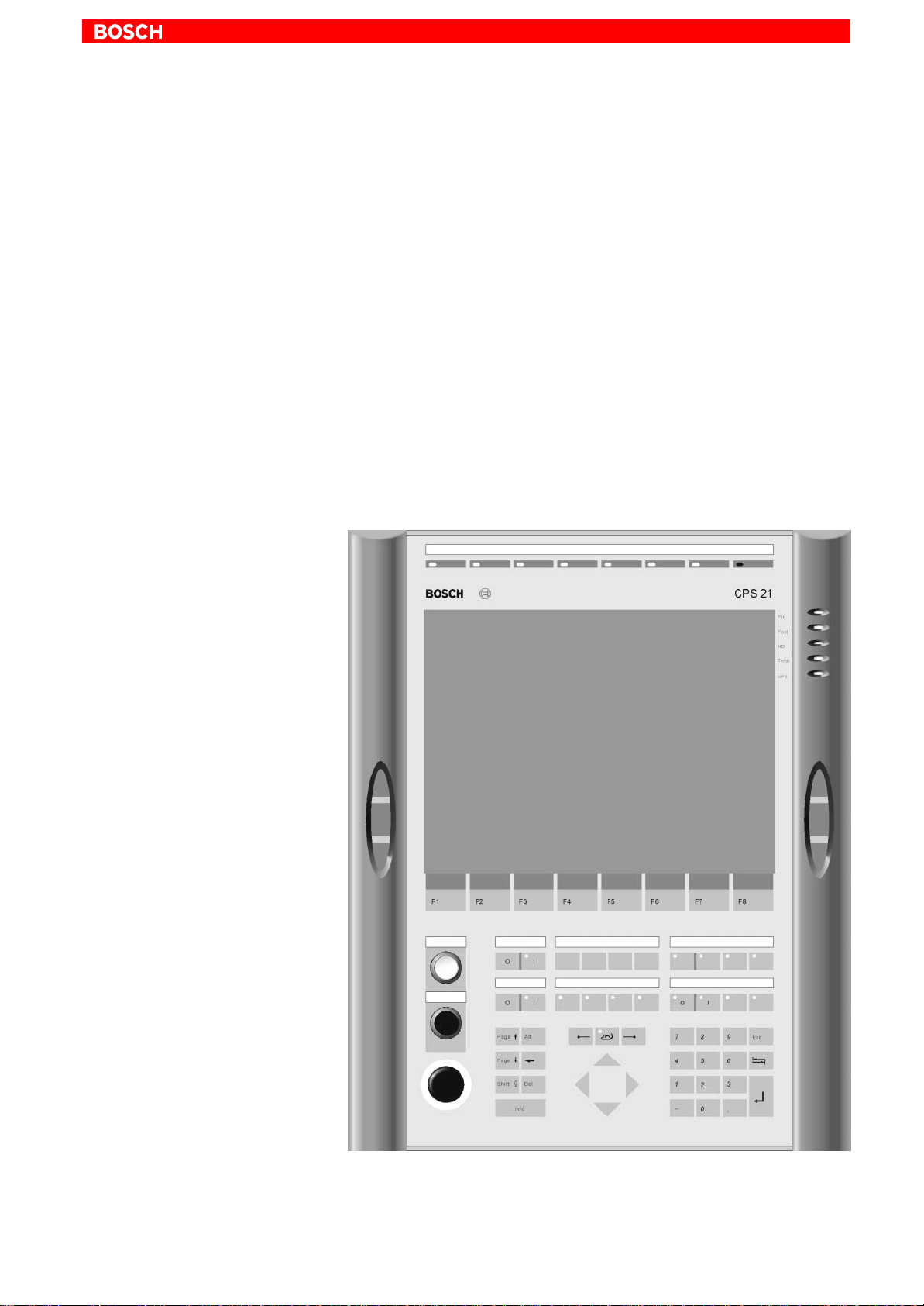
Front view CPS21_3
System Overview CPS21_3 / CPS21_4
2–2
1070 073 825-103 (02.04) GB
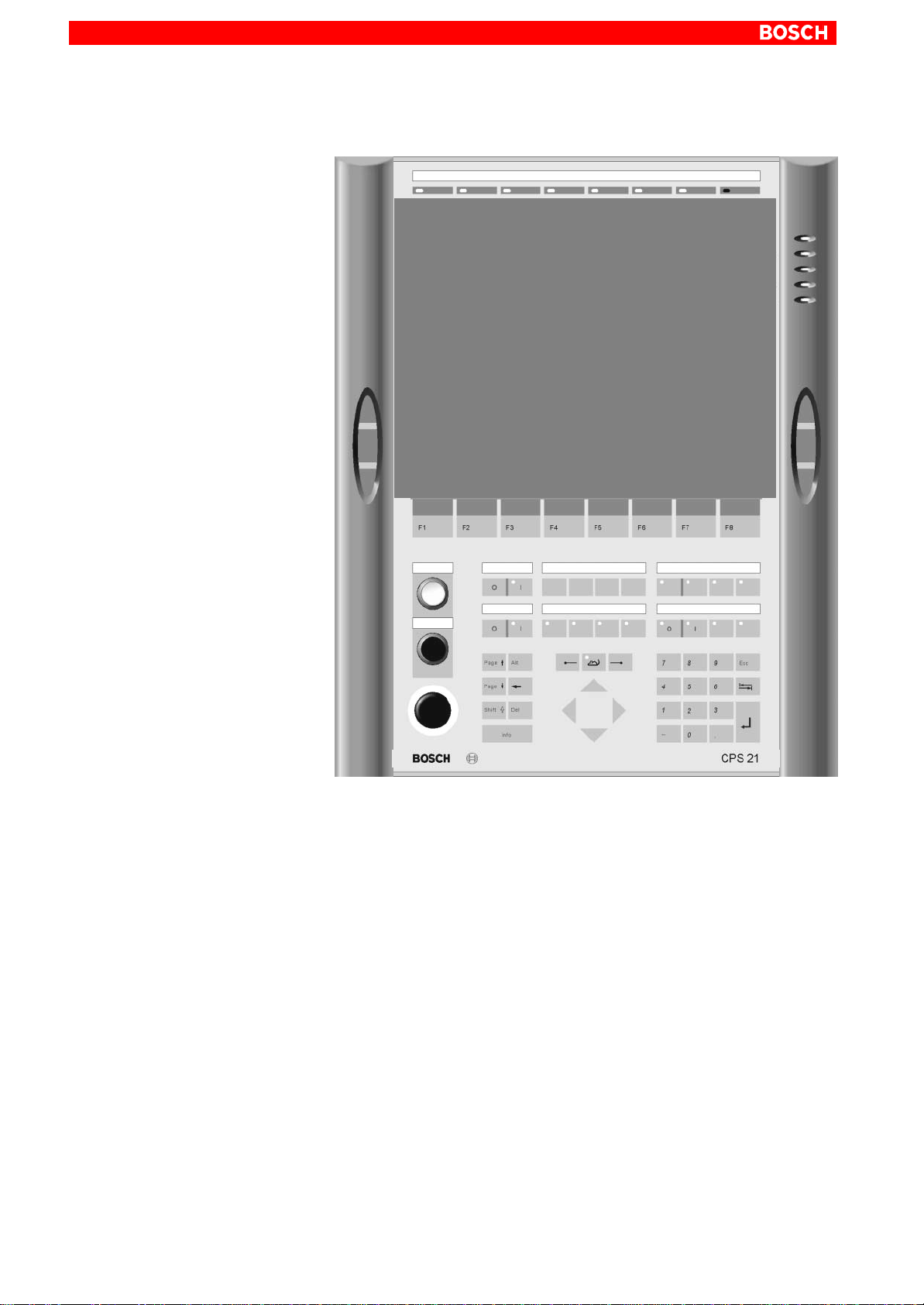
Front view CPS21_4
Housing: The PC is completely covered by an anodized alumi-
num housing and is internally and externally equip-
ped with cooling fins. Under the given operating
conditions (see section 2.6), this ensures passive
cooling for the integrated PC.
Frame and
Handles: A plastic frame is connected to the housing by 2 hin-
ges. A handlebar with three navigation buttons is fa-
stened on each side –left and right –of the frame in
order to provide a user friendly operation. On its rear
side, the PC is fastened to the plastic frame.
Front panel: Display, membrane keyboard and the PC which, at its
rear side, is fixed to the plastic frame are fastened to
the front panel. If the frame and the front panel are
swung to the side, the display and the hard disk can
easily be replaced after the PC box has been remo-
ved (see section 8).
Insertion-
labels: Up to five labels are available for individual button
description.
Suspension: The entire unit is suitable for floor or suspended
mounting. (refer to section 4.3).

System Overview CPS21_3 / CPS21_4 2–3
1070 073 825-103 (02.04) GB
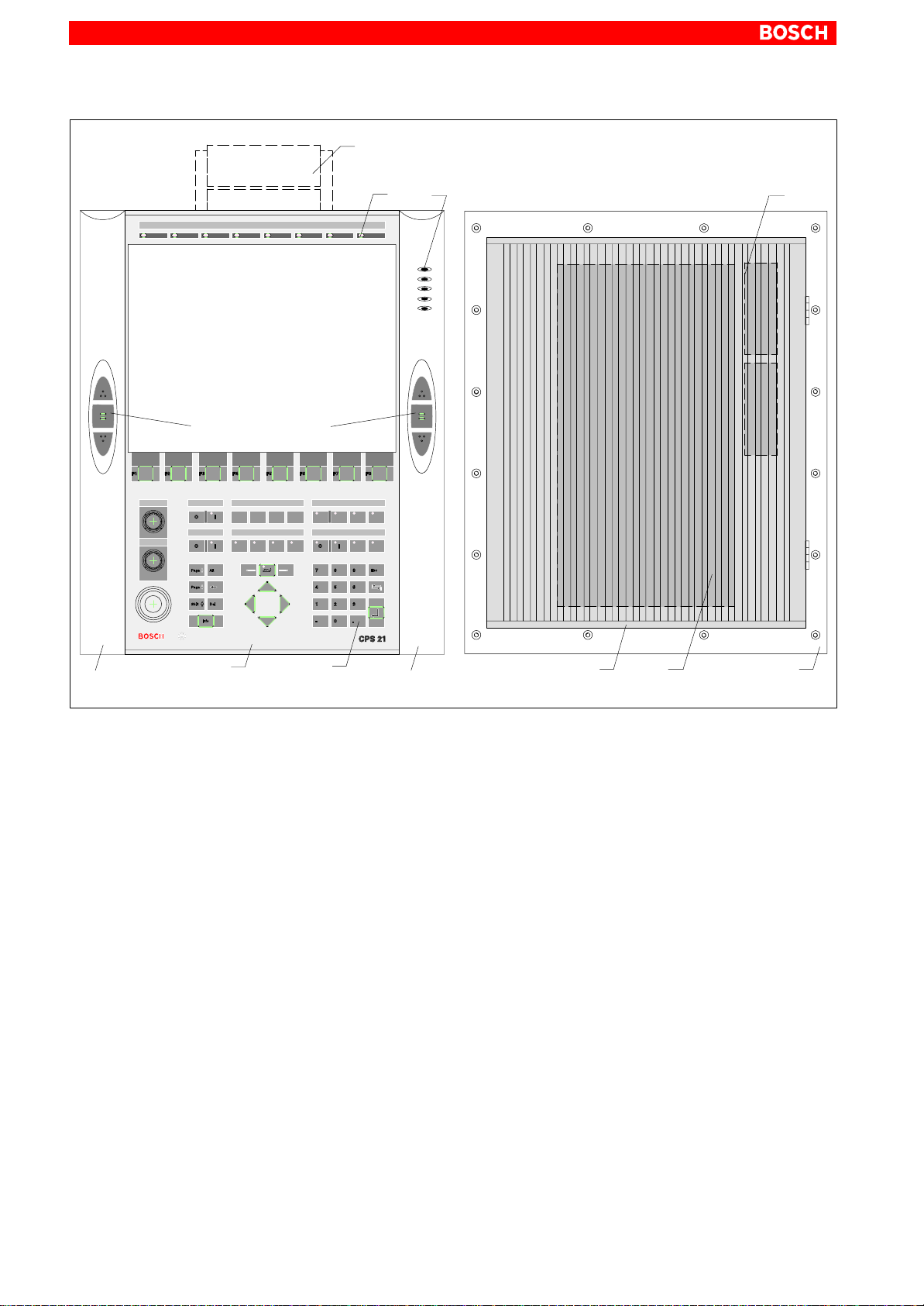
CPS21_3
Aluminum housing
Handle
Handle
13.8”Color TFT Display
Keyboard
Front panel
LEDs
Plastic
frame
PC
(internal)
Battery
(internal)
Navigation keys
Tilt/tip adapter
System Overview CPS21_3 / CPS21_4
2–4
1070 073 825-103 (02.04) GB
CPS21_4
Aluminum housing
15”Color TFT Display
LEDs
Plastic
frame
PC
(internal)
Battery
(internal)
Navigation keys
Tilt/tip adapter
Handle
Handle Keyboard
Front panel
System Overview CPS21_3 / CPS21_4 2–5
1070 073 825-103 (02.04) GB
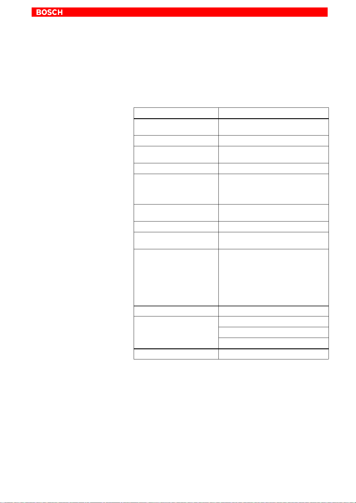
2.2 Technical Data
.All specifications are subject to change as a result of technological de-
velopments. This also means that components providing higher than
the specified performance (e.g. a faster processor) may be integrated
in the devices without explicit reference in this documentation.
Feature CPS21_3 / CPS21_4
Processor ≥Intel Pentium 266 MHz with MMXTtech-
nology (socket 7) or compatible CPU
Second level cache 512 KB
Random Access Memory
(DIMM-modules) 128 MB SDRAM
Hard Disk ≥3.2 GB (IDE)
Display 13.8”Color-TFT (CPS21_3)
or 15”Color-TFT (CPS21_4)
with non–reflecting and scratch–resistant
front screen
3 expansion slots PCI / ISA: 3 / 0 or 2 / 1,
ex works including 2 PCI cards
Power supply 24 VDC
UPS (uninterruptible
power supply) via integrated rechargeable battery pack
(2 series-connected 6 V battery packs)
Interfaces
(for detailed information, refer to
Section 6)
4 x serial,
1x parallel,
PS/2-keyboard and mouse
Ethernet,
USB,
key codes via 24 V out
2 x CAN bus and 1 x busmaster
(via expansion slots)
Weight: approx. 18.8 kg (without adapter)
Dimensions Housing external:509 x 432 x 177 mm
PC housing: 448 x 195 x 101 mm
Front panel: 499.5 x 409.5 x 5 mm
Operating system Windows NT4.0
System Overview CPS21_3 / CPS21_4
2–6
1070 073 825-103 (02.04) GB
2.3 Software
.For subsequent loading of software and for data backup, a floppy disk
drive or the connection to an Ethernet network is necessary. The drive
can be purchased separately.
BIOS software The BIOS software is licensed by Phoenix. With the BIOS software, the PC
boots until it finds an operating system that provides a more convenient and
user–friendly platform for running the application software.
The BIOS setup must not be altered. It is documented in the manual ”BT150,
BT200, BT250, CPS21_3 Software Configuration”.
Operating system The CPS21_3 / CPS21_4 has been equipped and tested with the following
operating systems from Microsoft Corp.:
DWindows NT (version 4.0), including possibly necessary NT service re-
leases from Microsoft Corp.
Utility programs Additionally, the following utility program is installed:
DUPSNT –Uninterruptible Power Supply Program for Windows NT
(is not part of the Windows NT operating system software).
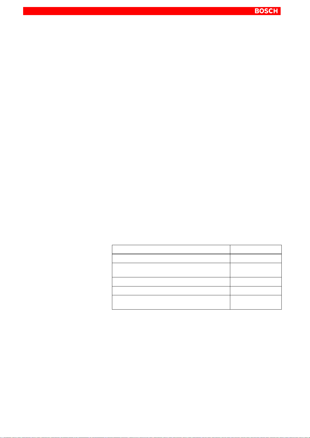
Application software The following optional Bosch software is available:
Application CPS21_3 / CPS21_4
PCL Software PLC •
MMI-Madap Software for control and diagnosis of
plant on request
WinSPS PLC programming software on request
WinCan Fieldbus parameter assignment for CAN bus on request
TSWIN Programming interface for
operating terminals on request
•= available;

System Overview CPS21_3 / CPS21_4 2–7
1070 073 825-103 (02.04) GB
2.4 Expansion Cards
The CPS21_3 / CPS21_4 has 3 slots for expansion cards with a maximum
length of 180 mm:
D2 PCI BUS cards and
D1 combination slot for 1 PCI or 1 ISA BUS card
must not be used if
ISA card is inserted
PCI bus slot
must not be used if
PCI card is
inserted
Slot A2
PCI bus slot
ISA bus slot
Combi-
nation
slot A3 PCI bus slot
Slot A1
CAUTION
Destruction of an expansion card or the motherboard!
PCI and ISA cards must never be inserted simultaneously in the PCI/
ISA-BUS combination slot!
The following expansion cards are used in the CPS21_3 / CPS21_4:
DPCI-CAN card: –CAN bus interface
DPCI_BM-CAN card: –CAN bus interface
–busmaster interface
PCI-CAN
card (on A1)
ISA/PCI combination slot A3
PCI-BM_CAN
card (on A2) Screw for fastening
slot cover
Slot cover
PCI-CAN
Slot cover
PCI_BM-CAN
.For interfaces, refer to section 6.14.2

System Overview CPS21_3 / CPS21_4
2–8
1070 073 825-103 (02.04) GB
In order to use other expansion cards, a driver software that is recommen-
ded by the card manufacturer might be necessary.
CAUTION
Using unauthorized expansion cards may result in damage to the PC
and/or the application software.
Please use only approved expansion cards, and have them installed
by a specialist.
2.4.1 BIOS Setup
PCI slot x In the BIOS submenu called “The Advanced Menu / PCI Configuration sub
menu”you can assign the interrupt request (IRQ) address to a specific PCI
slot. At the same time, the number of the IRQ address also defines the prio-
rity. If only PnP cards are used, then the BIOS setup ”AUTO”must be main-
tained.
BIOS selection:PCI IRQ line 1, PCI IRQ line 2, PCI IRQ line 3, PCI IRQ line 4
Option: Disabled, Auto, IRQ: 3, 4, 5, 7, 9, 10, 11, 12, 14, 15,
Default:AUTO
ISA slot (IRQ)
In the BIOS submenu ”The Advanced Menu / PCI Configuration sub menu /
PCI/PNP ISA IRQ Resource Exclusion / IRQx”, the IRQ Address for Legacy
ISA cards (ISA cards without plug-and-play capability) can be assignedper-
manently.
BIOS selection: IRQ:3, 4, 5, 7, 9, 10, 11, 15
Option: Available, Reserved
Default:Available
ISA slot (UMB) In the BIOS menu “The Advanced Menu / PCI Configuration sub menu /PCI/
PNP ISA UMB Region Exclusion”you can reserve a specific upper memory
block for Legacy ISA cards (without ”plug–and–play”capability) .
BIOS selection: C800 - CBFF, CC00 - CFFF, D000 - D3FF, D400 - D7FF,
D800 - DBFF, DC00 - DFFF
Option: Available, Reserved
Default: Available
CAUTION
Address conflicts (IRQ, memory access, I/O address) may cause
destruction of motherboard or ISA cards!
Please follow the instructions provided by the card manufacturer. If
necessary you must make new configuration settings in the BIOS
and in the operating system (e.g. Windows NT control panel).
This manual suits for next models
1
Table of contents
Popular Industrial PC manuals by other brands


Chipsee
Chipsee CS-A55-BOX manual

sammi
sammi SmartStation 10 user manual

DMP Electronics
DMP Electronics EBOX-ALJ3455 user guide

Moxa Technologies
Moxa Technologies V2406-24I Series Hardware user manual

Moxa Technologies
Moxa Technologies IA240-LX Quick installation guide

ADLINK Technology
ADLINK Technology DLAP-3200-CF Series user manual


