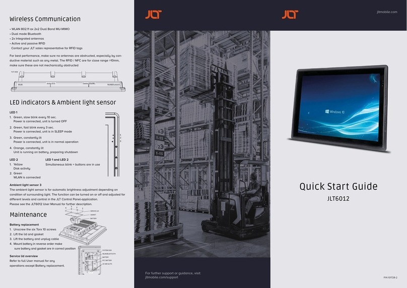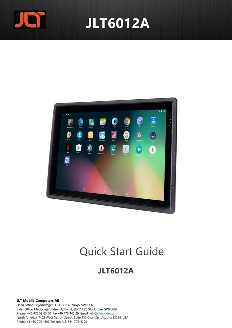
First startup
This device is running the Android™ operating system.
Follow instructions and steps given to complete the user setup.
See section “Maintenance” for SIM-card installation.
Touch screen
JLT6012A is equipped with a Projected Capacitive Touch screen. Also called PCT or
PCAP. The touch screen is calibrated from factory and needs no further calibration.
It has a resistant glass surface that can be cleaned with a damp cloth, ordinary
soap or hand-dish washing fluids. Purpose made cleaning fluids may also be used.
It’s normally operated with fingers, but can also be used with purpose designed
stylus for PCT or PCAP. A stylus designed for resistive touch screens will not work.
Interfaces
Connectors, from left to right:
• WWAN Main, SMA
• GNSS, SMA
• WWAN Aux, SMA
• USB2 x2, USB type A
• Ethernet, RJ45
• USB3.1, OTG, ADB, Display, USB type C
• USB3.1, USB type A
• RS232C, configurable 5V supply on pin1/9, D-Sub-9
• Isolated Power input, 9-72VDC, nominal input voltage 12-60VDC
– Pin 1 = Positive – Pin 2 = Remote On/Off – Pin 3 = Power Ground
Power cable
Connect cable as shown in the picture below. Remote may be connected to a re-
mote switch or a vehicle ignition key for automatic On/Off control where
high is on and low is off. IMPORTANT: If not used for remote operation,
remote input pin must be connected to positive input to enable
operation. JLT standard cable configuration:
Red = Positive, White = Remote, Black = Ground
The power cable must be dimensioned to handle up
to 40 Watts, or use cable supplied by JLT.
Recommended cable area 0.75 mm2, AWG 18 or larger.
Mounting
Cable Strain Relief and Rubber Sealing Plugs
Use included cable ties to attach cables to the strain relief plate.
Install rubber sealing plugs to unused ports.
Keyboard mount
An accessory keyboard mount is available from JLT that mounts towards the
two M6 screw holes on each side. Fasteners are included with the mount. If
other fasteners or screws are being used the depth of mounting holes are
maximum 8mm.
The keyboard mount has multiple mounting hole alternatives and comes with
a Velcro® adhesive tape to adapt to any keyboard. It’s adjustable to allow
different keyboards and height. Mounting screws come with the selected
keyboard, if supplied from JLT Mobile.
JLT provided Mounting Kits: RAM®
RAM® Mount -> Computer: Use included screws and washers.
Usage of thread locking products like Loctite® is recommended.
Mounting with other brands and parts
When mounting a JLT unit to a VESA bracket 75 x 75 mm, use M6 screws with
correct length. The inserting part of the screw should be minimum 5mm and
must NOT exceed 8.5mm (that is 8 complete turns on the screw).
If screws are too long, build up with washers to adjust the inserting part of the screw.
If this is not done and the screws are too long, they will deform the aluminum case
inwardly when applying great force.
Torque: Maximum 6Nm
Power input and UPS
The unit is equipped with an isolated wide range 9-72VDC input. Nominal input volt-
age 12-60VDC. If power is lost or switched off, the unit will switch to the UPS-battery
to perform a controlled system shutdown. Battery and remote operation are config-
urable in JLT Control Panel application.
Remote input is recommended to utilize to automatically power on and off the unit.
Typically connects to a vehicle ignition switch.
No additional grounding of unit is normally required.
Power consumption
Standby: 0.5W
Idle, active screen: typical 15W
Maximum: 40W
NOTE
As the surface is made of glass it will withstand most common substances, but do NOT
use fluids like bleach or any strong alkali cleaning agents such as sodium or potassium
hydroxide for cleaning as it may etch the glass and leave grey marks.
IMPORTANT
Do NOT apply any solder to the cable ends. It will eventually make the connection
unreliable and loose during use.
IMPORTANT
The vehicle computer and bracket must be firmly secured to a surface that can support
the vehicle computer´s weight and include optional accessories such as keyboard and
scanners. Computer weight = 2.9 kg or 6.4 lb
Buttons
From left to right:
• Power On/Off button: Press and hold 2 seconds for shut down menu, 8 seconds
for forced shutdown
• Brightness –
• Brightness +
• Android buttons: Home, Back and Menu
Wireless Communication
WLAN: 802.11ac/a/b/g/n 2x2 Dual Band MU-MIMO
Dual Mode Bluetooth and NFC
2x Integrated Antennas 2.4Ghz / 5Ghz
Optional: WWAN: 4G/3G, HSPA+, UMTS, LTE
GNSS: GPS, Glonass, Galileo, BeiDou
See section “Maintenance-Service lid overview” for SIM-card insertion.
For best performance, make sure no antennas are obstructed, especially by
conductive material such as any metal. The NFC are for close range >10mm,
make sure it’s physically accessible when mounting unit.
TOP VIEW


