manuals.online logo
Brands
  1. Home
  2. •
  3. Brands
  4. •
  5. Bosch
  6. •
  7. Extender
  8. •
  9. Bosch ISP-EM55FM-120 User manual

Bosch ISP-EM55FM-120 User manual

Safety
!
Caution!
Electricity
Injuries due to electricity are possible.
Switch off all electricity while installing
the product.
Do not open or modify this product, ex-
cept if described in this manual.
Old electrical and electronic appliances
Electrical or electronic devices that are no
longer serviceable must be collected separately
and sent for environmentally compatible recyc-
ling (in accordance with the European Waste
Electrical and Electronic Equipment Directive).
To dispose of old electrical or electronic
devices, you should use the return and collec-
tion systems put in place in the country con-
cerned.
Short information
This zone expander module integrates manual
conventional sensor technology (e.g. conven-
tional magnet contacts) into the local security
network (LSN).
System overview
1
2 3
4
5
6
Fig.1: System overview
Element Description
1 Recessed socket
2 Mount with PCB
3 Housing cover fastening screw
4 Adhesive seal
5 Housing cover
6 Fastening screws
Installation
Notice!
The recessed socket is not part of the
delivery. Use a recessed socket accord-
ing to DIN 49073 part I.
How to mount the zone expander module
1. Connect the PCB.
2. Place the mount with PCB into a re-
cessed socket and lock it in position us-
ing the two fastening screws.
3. Fit the housing cover on the mount with
PCB and secure it with the housing cover
fastening screw.
4. Put the adhesive seal onto the housing
cover fastening screw.
Connection
!
Caution!
Incorrect cabling
Incorrect cabling leads to malfunction
of the system.
!
Caution!
Cable length
Exceeding the permitted cable length is
not covered by CE declarations and
leads to malfunction of the system.
– Do not exceed the total cable length of 500
m per loop for the primary cables, the con-
trol cables and the contact cables of EM 55,
KD55/1, NKK, NNK 100 2-wire, NVK and IC
400.
Permitted cable length of the primary cables
(PL)
– Maximum length of unshielded cable: 3 m
– Maximum length of shielded cable: 500 m
LSN connection
– Voltage supply can be fed-through (other-
wise free terminals for 0V/+U).
– Incoming and outgoing LSN can be swapped
over.
4-wire and 2-wire connections
Notice!
A mixed operation of a 4-wire connec-
tion at one of the primary outputs and
a 2-wire connection at the other
primary output is not permitted.
Notice!
For a 4-wire connection always use un-
shielded cables.
For a 2-wire connection always use
shielded cables.
4-wire connection (unshielded)
– Use a 4-wire connection with an unshielded
cable with a maximum length of 3 m and the
internal EOL resistor (e.g. for magnetic con-
tacts).
– With an unshielded cable, do not connect
contacts with metallic enclosure.
LSN
aLSN1
bLSN1
0V
+U
LSN
aLSN1
bLSN1
aLSN2
bLSN2
0V
I1
I2
I3
I4
II5
I6
II1
II2
II3
II4
II6
RE1
RE2
PL1
PL2
RE1
RE2
I5
I7
+U
aLSN2
bLSN2
0V
+U
II7
1
2
2
3
Element Description
1 Terminal for fed-through voltage sup-
ply
2 LSN connection
3 4-wire connections, e.g. magnet con-
tacts (unshielded)
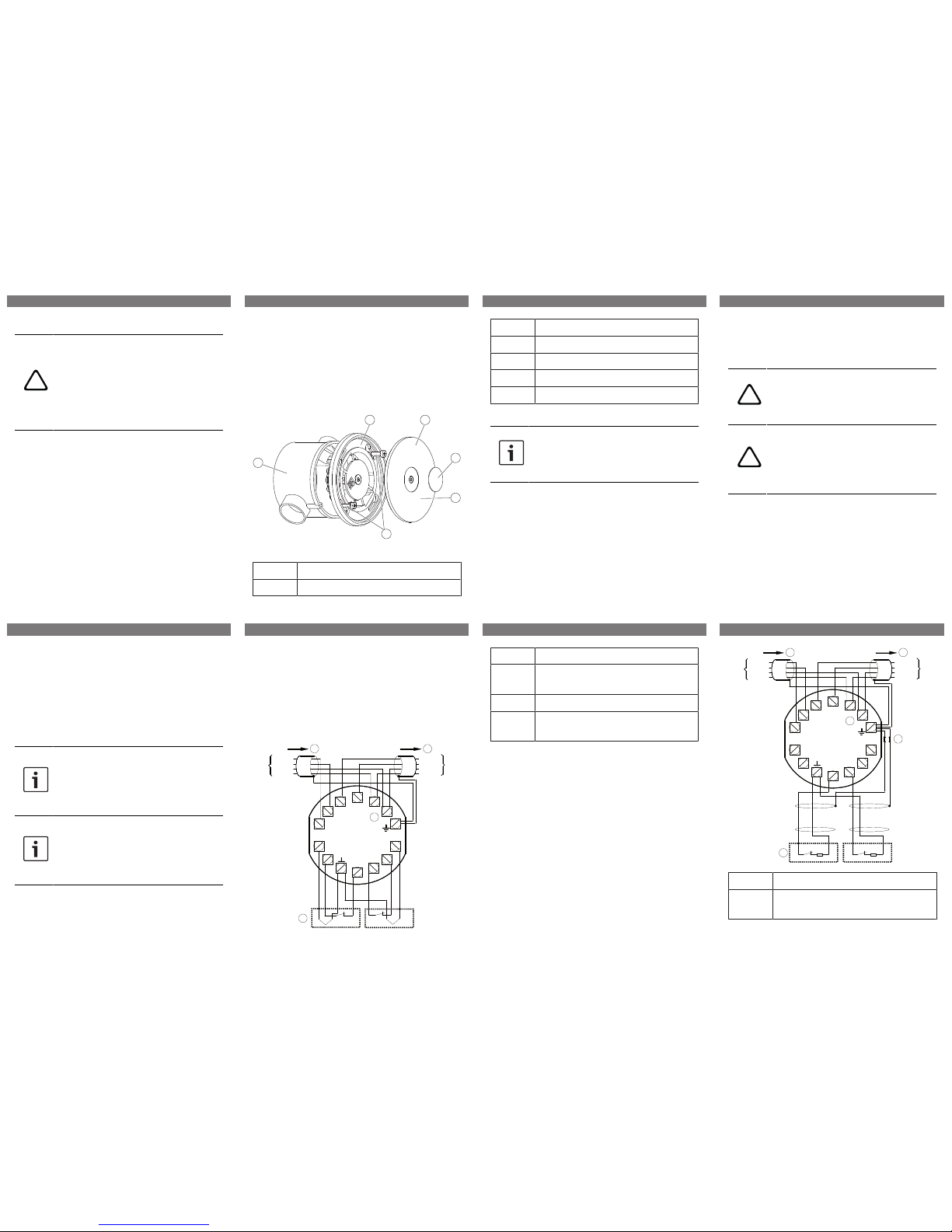
2-wire connection (shielded)
– Use a 2-wire connection with a shielded
cable with a maximum length of 500 m and
an external EOL resistor (e.g. for lock con-
tacts).
– Connect shielding only to the zone expander
module.
– Use one ferrite bead per shielding.
LSN
aLSN1
bLSN1
0V
+U
LSN
aLSN1
bLSN1
aLSN2
bLSN2
0V
I1
I2
I3
I4
II5
I6
II1
II2
II3
II4
II6
RE1
RE2
PL1
PL2
RE1
RE2
I5
I7
+U
aLSN2
bLSN2
0V
+U
II7
1
2
2
R
R
3
4
Element Description
1 Terminal for fed-through voltage sup-
ply
1 | 2 | 3 | 4 |
5 | 6 | 7 | 8 |
2 LSN connection
3 Ferrite bead
4 2-wire connections, e.g. lock contacts
(unshielded)
DIP switch settings
O
1 2 3 4 5 6
D I P
N
7 8
On Off
Technical data
Electrical
Minimum operating voltage in
VDC
10
Maximum operating voltage in
VDC
33
Maximum current consump-
tion in mA
0.4
Number of primary lines 2
Mechanical
Dimension in cm (Ø x D) 7.6 x 2.5
Housing material ABS
Color RAL 9002
Weight in g 54 g
Environmental
Minimum operating temperat-
ure in °C
0
Maximum operating temperat-
ure in °C
50
Protection class IP40
Security level IK04
Environmental class II
9 | 10 | 11 |
12 | 13 | 14 |
ISP-EM55FM-120 LSN 2 Zone Expander
Module, Recessed Mounting
en Quick Installation Guide
Bosch Sicherheitssysteme GmbH
Robert-Bosch-Ring 5
85630 Grasbrunn
Germany
www.boschsecurity.com
© Bosch Sicherheitssysteme GmbH, 2015
| 2015.10 | 09 | F.01U.318.467

Other Bosch Extender manuals

Bosch CM710B How to use

Bosch

Bosch CM710B How to use

Bosch LTC 8713 Series User manual

Bosch

Bosch LTC 8713 Series User manual

Bosch ISP-EM55FM-120 User manual

Bosch

Bosch ISP-EM55FM-120 User manual

Bosch CM704B User manual

Bosch

Bosch CM704B User manual

Bosch FPC 7034 User manual

Bosch

Bosch FPC 7034 User manual

Bosch LTC 8714 User manual

Bosch

Bosch LTC 8714 User manual

Popular Extender manuals by other brands

Comprehensive CHE-HDBT300U user manual

Comprehensive

Comprehensive CHE-HDBT300U user manual

D-Link EXO DRA-1360 user manual

D-Link

D-Link EXO DRA-1360 user manual

ATEN VE849 user manual

ATEN

ATEN VE849 user manual

Simplified MFG EX2ARC user manual

Simplified MFG

Simplified MFG EX2ARC user manual

Intelix DIGI-HD70 installation guide

Intelix

Intelix DIGI-HD70 installation guide

Ophit FTSM user guide

Ophit

Ophit FTSM user guide

SIIG AV-GM04Q3-S1 manual

SIIG

SIIG AV-GM04Q3-S1 manual

Nikrans LCD-800GD quick start guide

Nikrans

Nikrans LCD-800GD quick start guide

Foxun SX-EX37 operating instructions

Foxun

Foxun SX-EX37 operating instructions

SC&T HE02ER user manual

SC&T

SC&T HE02ER user manual

MyAmplifiers AT-7100 installation guide

MyAmplifiers

MyAmplifiers AT-7100 installation guide

Gefen USB-MIDI user manual

Gefen

Gefen USB-MIDI user manual

Avenview FO-VGA-DVI user guide

Avenview

Avenview FO-VGA-DVI user guide

DAB PUMPS LTD. E.SYBOX MINI 3 quick guide

DAB PUMPS LTD.

DAB PUMPS LTD. E.SYBOX MINI 3 quick guide

Matchmaster 34MM-2K50-3 instruction manual

Matchmaster

Matchmaster 34MM-2K50-3 instruction manual

BUSCH Panda WV 4500 B instruction manual

BUSCH

BUSCH Panda WV 4500 B instruction manual

Elabs HX100M instruction manual

Elabs

Elabs HX100M instruction manual

Lightware DVI-HDCP-TPS-TX95 quick start guide

Lightware

Lightware DVI-HDCP-TPS-TX95 quick start guide

manuals.online logo
manuals.online logoBrands
  • About & Mission
  • Contact us
  • Privacy Policy
  • Terms and Conditions

Copyright 2025 Manuals.Online. All Rights Reserved.