Bosch CM710B How to use

CM710B
4 Way Output Expander Module
Security System
Installer Reference Guide
EN
Security Systems

Page 2 P/N: CM710BIRG Rev 1.3 E&OE Copyright © 2012
CM710B - 4 Way Output Expander Module
The CM710B Relay Output Module can be added to the Solution 16i, Solution 144 or Solution E control panels to
increase the number of programmable outputs available on the system. Outputs can be used to operate LED Indica-
tors, Garage Doors, Lighting, Sprinklers, Pumps, Air Conditioning, Door Strikes etc.
Each output includes Normally Open (NO), Normally Closed (NC) and Common (COM) terminals. Figure 2: includes
examples showing control of an LED indicator and two door strikes in an access control application.
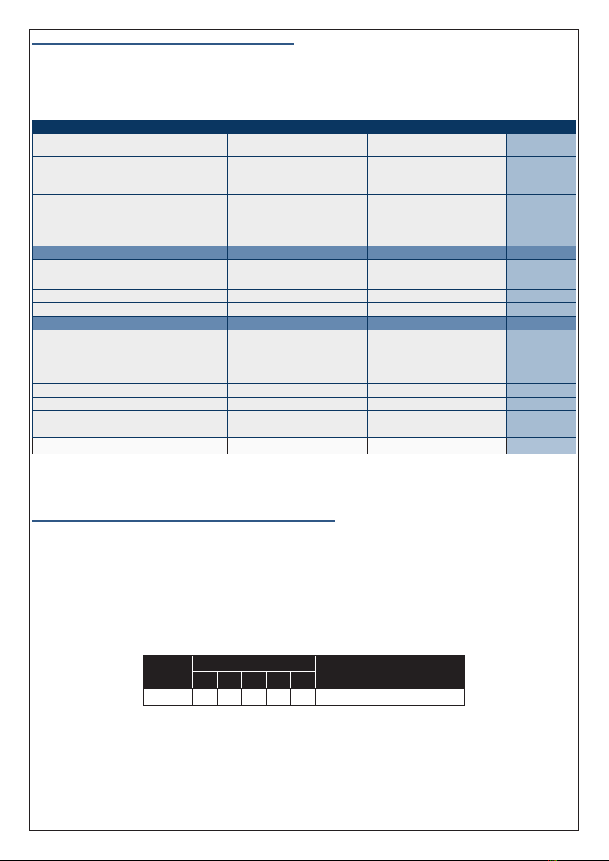
CM710B Output Expander Compatibility
Panel Supported Modules Supported
Solution 16i 1
Solution 144 8
Solution E 16
Table 1: CM710B Compatibility
Features
The CM710B module is LAN based, and can be remotely located from the main panel and connected via the 4 wire
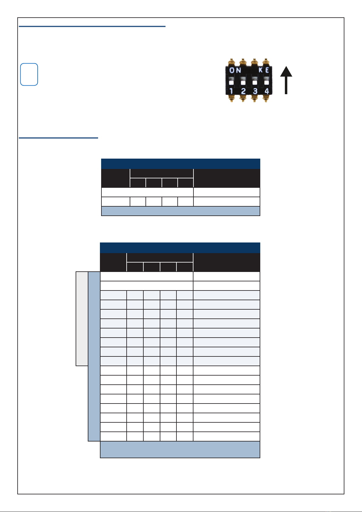
RS485 system LAN. Each CM710B module must be assigned a unique address using the on-board dip switches.
See Table 2: and Table 3: for a list of valid module addresses and the corresponding output mappings for each mod-
ule.
Always connect new modules while the system is powered down. The control panel will only recognise new mod-
ules after power up.
A dedicated service keypad and tamper input are provided. If the tamper input is not required, you should fit the
supplied shunt to the tamper input pins. To assist with installation, the module includes indicators to show module
and individual output status at all times.
A four way dip switch is used to select the output expanders address. The address setting determines the output
numbers for each expander as shown in Table 2: and Table 3: on page 3. You should consult these tables before
you begin output programming
Programming
Output programming options are fully detailed in the panel installation and quick reference guides.
The following sequence outlines the correct output programming procedure.
1) Program the output name. Output names are used to simplify programming, user interaction and reporting.
2) Program the output event type. Over 60 different event types are available to suit a variety of application.
3) Program the output event assignment.
4) Program the output polarity.
5) Program the output time parameter.
6) Program any specific output options.
Programming Considerations
1) The CM710B expander does not need to be enabled via panel programming. The panel will recognise it after
power cycle or after performing a LAN scan function (MENU 6-0-2).
2) Some outputs are defaulted as Not Used in panel programming. These must be programmed as valid event types
before they become active.

P/N: CM710BIRG Rev 1.3 Page 3
Copyright © 2012 E&OE
Module Address Switches and Output Numbering
Table 2: and Table 3: list the module address settings and corresponding output numbers that apply when adding
output expanders to the listed panels. Each output expander module added to the Solution 16i will provide a maxi-
mum of 4 additional outputs.
i
Note
Only one CM710B can be assigned to each address. All mod-
ules are supplied from the factory set to address 1. You must
power cycle the panel or perform a LAN scan whenever you
change the module address. The LAN must be in the unlocked
state or the LAN scan will not find new modules.
Panel Output Assignments
The following tables list the output numbers which become available when adding output expander modules to the
system.
Solution 16i Panel
Module
Number
Address Setting Output
Numbers
SW1 SW2 SW3 SW4
Control Panel 1 to 4
1 = OFF OFF OFF OFF 5 to 8
1 x CM710B can be fitted to the Solution 16i panel.
Table 2: CM710B Address Configuration On Solution 16i Panel
Solution 144 and Solution E Panels
Module
Number
Address Setting Output
Numbers
SW1 SW2 SW3 SW4
Solution 144 Panel
Solution E Panel
Control Panel 1 to 5
Virtual Outputs 6 to 8
1 = OFF OFF OFF OFF 9 to 12
2 = ON OFF OFF OFF 13 to 16
3 = OFF ON OFF OFF 17 to 20
4 = ON ON OFF OFF 21 to 24
5 = OFF OFF ON OFF 25 to 28
6 = ON OFF ON OFF 29 to 32
7 = OFF ON ON OFF 33 to 36
8 = ON ON ON OFF 37 to 40
9 = OFF OFF OFF ON 41 to 44
10 = ON OFF OFF ON 45 to 48
11 = OFF ON OFF ON 49 to 52
12 = ON ON OFF ON 53 to 56
13 = OFF OFF ON ON 57 to 60
14 = ON OFF ON ON 61 to 64
15 = OFF ON ON ON 65 to 68
16 = ON ON ON ON 69 to 72
Up to 16 x CM710B can be fitted to the Solution E panel.
Up to 8 x CM710B can be fitted to the Solution 144 panel.
Table 3: CM710B Address Configuration On Solution E and Solution 144 Panels
ON
Position
Figure 1: Address Switch Activation

Page 4 P/N: CM710BIRG Rev 1.3 E&OE Copyright © 2012
Output Defaults - Solution 144 and Solution E Panels
The table below list the default values for all output parameters in the Solution 144 and Solution E. Outputs 1 to 4
are High current digital outputs and Output 5 is the on board relay output. Outputs 9 to 72 are only available if the
optional Output Relay Expander Modules (CM710B) or Universal Expander Modules (CM705B) are fitted. Options
marked N/A = Not Applicable.
Programming Option Output 1 Output 2 Output 3 Output 4 Output 5 Output 9 - 40
Output Name External
Siren
Strobe
Light
Smoke Sensor
PWR
Internal
Siren
On Board
Relay Output x Name
Event Type
36
(External
Siren)
48
(Strobe)
49
(Smoke Sensor
GND)
37
(Internal
Siren)
54
(Keyfob
Function 2)
00
(Not Used)
Event Assignment 0 0 0 0 0 0
Output Polarity
14
Speaker
Output
6
1 Shot Low +
Reset
11
Low 1 Shot
Open
6
1 Shot Low +
Reset
4
Open 1 Shot
Low
0
Open
To Low
Time Parameter
N° Of Hours 000 008 000 000 000 000
N° Of Minutes 005 000 000 005 000 000
N° Of Seconds 000 000 010 000 002 000
N° Of 1/10 Seconds 000 000 000 000 000 000
Output Options
Off On Low Battery Y Y N Y N N
Guest Control N N N N N N
Reserved N N N N N N
Monitor Overload Y Y Y Y N N
Monitor Device Fail Y Y N Y N N
Alarm On Device Fail N N N N N N
Block If All On N N N N N N
Show Status On Keypad N N N N N N
Table 4: Solution 144 and Solution E Output Defaults
Zone Allocation When Using the CM705B Universal Expander
The Solution 144 and Solution E panels also support the CM705B Universal Expander Modules. The CM705B is like
having 1 x CM704B zone expander, 1 x CM710B output expander and 1 x CM720B power supply module all in one
and as such, each universal expander added to the system will consume the address of the corresponding single
function module.
For example if a universal expander is assigned to address 4, then you cannot assign a CM704B, CM710B or CM720B
module to address 4 and the outputs corresponding to module 4 will be provided on the universal expander as per
the table below. See the CM705B installation guide for more information.
Module
Number
Address Setting Output Number
SW1 SW2 SW3 SW4 SW5
4 = ON ON OFF OFF OFF 21 to 24
Table 5: Outputs Allocated To Module Address 4

P/N: CM710BIRG Rev 1.3 Page 5
Copyright © 2012 E&OE
Output Event Types - Solution 144 and Solution E Panels
The table below list the various output event types which are available on the Solution 144 and Solution E control
panels. Refer to the full installation manual for more detail on the individual event types.
Output Event Type Table
00 - Disabled P 26 - Entry Timing A 52 - Exit Error A
01 - Battery Trouble P 27 - Exit Timing A 53 - Keyfob Function 1 A
02 - AC Trouble P 28 - End Of Exit Time A 54 - Keyfob Function 2 A
03 - Telco Line Fail P 29 - Chime On A 55 - Output In PreDelay Op
04 - Comm Fail Rr 30 - Chime Zone Faulted A 56 - Follow PIN Code Ur
05 - 3rd Dial Attempt Rr 31 - Auto Arm Pre Alert A 57 - Part Entry Time A
06 - Dest Reporting Rr 32 - Ready To Arm All On A 58 - TimeZone Tz
07 - Disabled 33 - Ready To Part Arm A 59 - Temperature Hi/Lo Kp
08 - Destination Kiss Off Rr 34 - Ready To Part 2 Arm A 60 - Door Dr
09 - Keyfob Function 1 Ur 35 - Close Sent OK A 61 - Door Open Too Long Dr
10 - Keyfob Function 2 Ur 36 - External Audible A 71 - CLI Trigger CLI
11 - Dialler Disabled P 37 - Internal Audible A 72 - GSM Signal Lost P
12 - Output Device Missing P 38 - Any Zone Alarm A 73 - GPRS Failure P
13 - Output Trouble Op 39 - Fire Alarm A 74 - Ethernet Fail P
14 - Panel On Line P 40 - Burglary Alarm A 75 - Macro Ma
15 - Incoming Call P 41 - Silent Alarm A
16 - System Trouble P 42 - Duress Alarm A
17 - Box Tamper Zn 43 - Keypad Medical A
18 - Zone Trouble Zn 44 - Keypad Fire A
19 - Zone Mirror Zn 45 - Keypad Panic A
20 - Zone Alarm A 46 - Device Tamper A
21 - Area Disarmed A 47 - Access Denied A
22 - Area Part Or All On A 48 - Strobe A
23 - Area All On A 49 - Smoke Sensor GND A
24 - Area Part On A 50 - Sensor Watch A
25 - Area Part 2 On A 51 - Senior Watch A
Legend:
(Ma) = Macro (P) = Panel Event Assignment (Ur) = User Event Assignment
(CLI) = CLI Trigger Table (Op) = Output Event Assignment (Tz) = Time Zone Event Assignment
(A) = Area Event Assignment (Zn) = Zone Event Assignment (Dr) = Door Group Event Assignment
(Kp) = Keypad (Rr) = Reporting Destination
Table 6: Output Event Types
i
Note
The event types available on the Solution 16i panel differ from those in
the above table. Please refer to the Solution 16i Quick Reference Guide
for detailed event type information.

Page 6 P/N: CM710BIRG Rev 1.3 E&OE Copyright © 2012
CM710B Connection Diagram - Rev F PCB
TO SYSTEM LAN
N12138
N12138
VISION
Powered by
4 Way LAN Relay Output Module
DIGIFLEX
P/Nº:
MFG:
CM710
01-Apr-12
VER: 2.00
E
L
E
C
T
R
O
N
I
C
S
DIGIFLEX
S
E
C
U
R
I
T
Y
TM
N12138
N12138
P/Nº:
MFG:
CM710B
24-Oct-12
4 Way Output Exp
RS485
VER: 2.05
RoHS
V
+-
Door Strike 1
Door Strike 2
+
+
-
-
*
*
1K
LED
Output Module earthing
point. Must be connected
to mains earth for maximum
lightning protection.
Connection point for
service keypad.
LAN Termination
Shunt.
Only fit the shunt if
this module is one of
the two furthest mod-
ules from the Control
Panel.
Output Expander Status LED flashes to
indicate that the Expander is functioning
correctly and communicating with the
panel. If the light is on steady it means
that the expander module is not commu-
nicating with the panel.
Output Expander Address
Select Switch. Each CM710B
fitted to the system must be
set to a unique address via this
switch.
Tamper Connection
Fit shunt if tamper
not required.
i
Note
When controlling inductive loads such as Door Strikes always install protection diodes as shown.
Note the Cathode or marked end of the diode connects to the (+) positive voltage.
When using the outputs to switch power from an external power supply you must only connect
the negative of the power supply to the negative of the CM710B module (LAN -).
Wiring examples show Output 2 controlling an LED indicator with power for
the LED taken from the LAN and Outputs 3 and 4 controlling door strikes
with power taken from an external power supply. Output 1 is not connect-
ed.
Figure 2: CM710B Connection Diagram
EXTERNAL P/S
Power Supply Type and
Voltage Depends On Type
Of Door Strike Used - AC
or DC
Back EMF Diodes 1N4001 or equivalent. Place
as close to the strike as possible. Note polarity.
Version F and later revision of the CM710B include 4 push
button switches which can be used to operate the corre-
sponding relay outputs on the expander module.
These can be used to test the output wiring is working
correctly during installation.

P/N: CM710BIRG Rev 1.3 Page 7
Copyright © 2012 E&OE
CM710B Specifications
Part Number: CM710B - 4 Way Relay Output Expander Module (RS485 LAN)
Operating Voltage: 10.0V DC. - 14.5V DC. @ 30mA Max 200mA. ( All relays and LEDs Operated)
Outputs: 4 x Form C Relay Outputs - Contact rated at 24V DC @2A Max
Module Connection:
(RS485 LAN)
Max total LAN length using multi strand security cable = 300m ,
Max total LAN length using 2 pair twisted shielded data cable (Belden 8723) = 1200m.
See manual for complete wiring instructions.
Operating
Environment: 0˚ to 55˚C RH 5 to 85% at 30˚C non-condensing.
Fixing Method: The CM710B can be mounted in the MW700, MW710, MW720 or MW730 enclosures using clip in
PCB mounts supplied.
Warranty: 3 years from date of manufacture (return to base)
N12138N12138 RoHS
In the interest of ongoing product development this
document is subject to change without notice.
Output Defaults - Solution 16i Panels
The table below list the default values for all output parameters in the Solution 16i panel. Outputs 1 to 4 are high
current digital outputs. Outputs 5 to 8 are only available if the optional output expander board (CM710B) is fitted.
Options marked N/A = Not Applicable.
Solution 16i Default Output Programming
Programming Option Output 1 Output 2 Output 3 Output 4 Output 5-8
Output Name External
Siren
Strobe
Light
Smoke Sensor
PWR
Internal
Siren
Output ?
Name
Event Type
36
(External
Siren)
48
(Strobe)
49
(Smoke
Sensor GND)
37
(Internal
Siren)
0
Event Assignment 0 0 0 0 0
Output Polarity 14 6 11 6 0
Time Parameter
N° Of Hours 000 008 000 000 000
N° Of Minutes 005 000 000 005 000
N° Of Seconds 000 000 010 000 000
N° Of 1/10 Seconds 000 000 000 000 000
Output Options
Do not Operate If Low Battery Y Y Y Y N
Display Output Overload Y Y Y Y N/A
Report Output Overload Y Y Y Y N/A
Display Missing Output Device Y N N N N/A
Report Missing Output Device Y N N N N/A
Alarm On Device Fail N N N N N/A
Block Output If Armed All On N N N N N
Display Status On Keypad N N N N N
Table 7: Solution 16i Output Defaults

Bosch Security Systems
25 Huntingwood Drive
Huntingwood, NSW 2148
Australia
Phone: +612 9672 1777
Facsimile: +612 9672 1717
© 2012 Bosch Security Systems
CM710BIRG
Issue FTR1.3
Table of contents
Other Bosch Extender manuals