English | 9
Bosch Power Tools 1 619 929 L41 | (18.6.12)
Operation
fCheck the levelling and indication accuracy of the
measuring tool each time before using and after longer
transport of the measuring tool.
fProtect the measuring tool against moisture and direct
sun light.
fDo not subject the measuring tool to extreme tempera-
tures or variations in temperature. As an example, do
not leave it in vehicles for long time. In case of large varia-
tions in temperature, allow the measuring tool to adjust to
the ambient temperature before putting it into operation.
In case of extreme temperatures or variations in tempera-
ture, the accuracy of the measuring tool can be impaired.
fAvoid any impact to or dropping of the measuring tool.
After severe exterior effects to the measuring tool, it is rec-
ommended to carry out an accuracy check (see “Accuracy
Check of the Measuring Tool”, page 10) each time before
continuing to work.
fPlace the measuring tool in the provided case when
transporting it over larger distances (e.g. in the car).
Ensure that the measuring tool is correctly placed in
the transport case. When placing the measuring tool in
thecase,the compensatorislocked; otherwise,itcouldbe
damaged in case of intense movement.
Setting Up/Aligning the Measuring Tool
Mounting on the Tripod
Set up the tripod stable and safe against tipping over or slip-
ping off. Place the measuring tool via the tripod mount 13 on-
to the male thread of the tripod and screw the measuring tool
tight with the locking screw of the tripod.
Roughly level the tripod.
Over short distances, the measuring tool can be carried
mounted on the tripod. To ensure that the measuring tool is
not damaged during this, the tripod must be held vertically
during transport, and should not be carried lengthwise over
the shoulder.
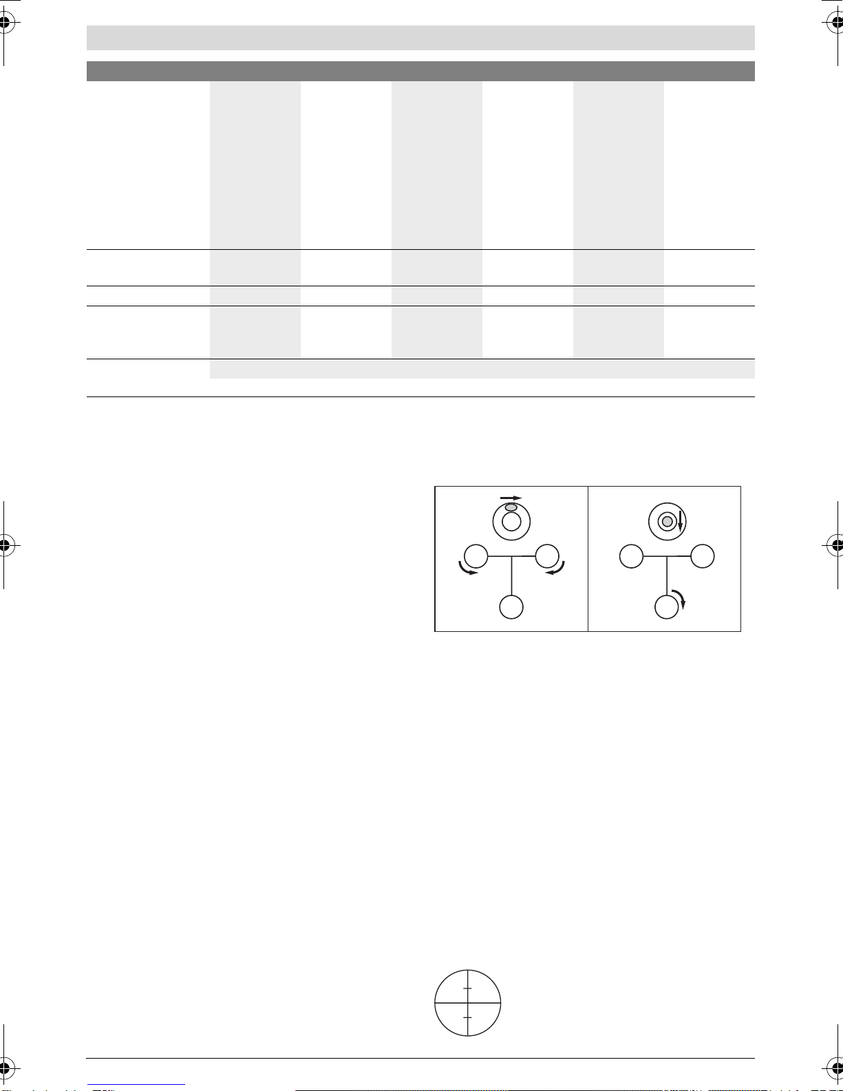
Aligning the Measuring Tool
Align the measuring tool with the levelling screws 12 so that
theairbubbleis positionedinthecentreof thecircularbubble
vial 7.
Turnthe first two levellingscrews Aand Bto move theair bub-
ble so that it is centred between the two levelling screws.
Then turn the third levelling screw Cuntil the air bubble is po-
sitioned in the centre of the circular bubble vial.
Any remaining deviation of the measuring tool to the horizon-
tal plane following the balancing of the circular bubble vial is
compensated by means of the compensator.
While working, regularly check (e.g. by viewing through the
bubble vial mirror 3) whether the air bubble is still in the cen-
tre of the circular bubble vial.
Centring the Measuring Tool over a Point on the Ground
If required, centre the measuring tool over a point on the
ground. For this, hang the plumb-bob 20 onto the locking
screw of the tripod. Align the measuring tool above the point
on the ground either by moving the measuring tool on the tri-
pod or by adjusting the tripod.
Focusing the Telescope
Remove the lens cap from the objective lens 1.
Direct the telescope against a bright object or
hold a white sheet of paper in front of the ob-
jective lens 1. Turn the eyepiece 6until the
crosshair appears sharp and deep black.
Telescope
–Image
– Magnification
– Field of view
– Clear objective
aperture
– Minimum measur-
ing distance
–Stadiaratio
– Stadia addition
erect
20x
1°30´
36 mm
0.3 m
100
0
erect
20x
1°30´
36 mm
0.3 m
100
0
erect
26x
1°30´
36 mm
0.3 m
100
0
erect
26x
1°30´
36 mm
0.3 m
100
0
erect
32x
1°30´
36 mm
0.3 m
100
0
erect
32x
1°30´
36 mm
0.3 m
100
0
Horizontal circle
graduation 1° 1gon 1° 1gon 1° 1gon
Tripod mount 5/8" 5/8" 5/8" 5/8" 5/8" 5/8"
Weight according to
EPTA-Procedure
01/2003 1.7 kg 1.7 kg 1.7 kg 1.7 kg 1.7 kg 1.7 kg
Degree of protection IP 54 (dust and splash water protected)
Automatic level GOL20D GOL20G GOL26D GOL26G GOL 32 D GOL 32 G
The measuring tool can be clearly identified with the serial number 15 on the type plate.
C
BA
C
BA
2.1.
OBJ_BUCH-1239-002.book Page 9 Monday, June 18, 2012 10:51 AM