Bosche WTS User manual

User manual WTS Ver.1.16
Seite 1von 52
WTS
User manual
Status 1.16
Status: 31.08.2022
Version 1.16 .
User manual WTS Ver.1.16
Seite 2von 52
Foreword These operating instructions provide you with detailed
information about the WTB weight measurement system. It
introduces you to set-up, commissioning and operation.
These instructions contain safety instructions to guarantee
safe use of the weight measurement system.
The manufacturer strives to improve their products on an
ongoing basis. They reserve the right to carry out any and all
modifications and improvements that they consider to be
necessary. However, this means that there is no obligation to
carry out retrospective modifications in this connection.
Before using the weight measurement system, you must have
read and understood the operating instructions and the safety
regulations that they contain.
Caution! Risk of electric shock.
Caution
This operation must be performed by skilled personnel.
Attention
Pay particular attention to the following instructions.
A notice
Further information.

User manual WTS Ver.1.16
Seite 3von 52
Table of Contents
1USER WARNINGS ..................................................................................................................................... 4
2RECOMMENDATIONS FOR CORRECT INSTALLATION OF WEIGHING INSTRUMENTS ................................. 4
3RECOMMENDATIONS FOR CORRECT INSTALLATION OF THE LOAD CELLS ................................................ 5
3.1 LOAD CELL INPUT TEST (QUICK ACCESS) ................................................................................................ 7
3.2 LOAD CELL TESTING ............................................................................................................................... 7
3.3 MAIN SPECIFICATIONS OF THE INSTRUMENT ........................................................................................ 8
4TECHNICAL SPECIFICATIONS..................................................................................................................... 9
5ELECTRICAL CONNECTIONS .................................................................................................................... 11
5.1 BASIC INFORMATION........................................................................................................................... 11
5.2 WIRING DIAGRAM ............................................................................................................................... 11
6LED AND KEY FUNCTIONS ...................................................................................................................... 12
7MENU MAP............................................................................................................................................ 13
7.1 SETPOINTS ........................................................................................................................................... 13
7.2 SYSTEM PARAMETERS ......................................................................................................................... 13
8INSTRUMENT COMMISSIONING ............................................................................................................ 14
9PROGRAMMING OF SYSTEM PARAMETERS ........................................................................................... 15
9.1 THEORETICAL CALIBRATION ................................................................................................................ 15
9.1.1 MAXIMUM CAPACITY ...................................................................................................................... 16
9.1.2 TARE WEIGHT ZERO SETTING .......................................................................................................... 16
9.1.3 ZERO VALUE MANUAL ENTRY ......................................................................................................... 16
9.2 REAL CALIBRATION (WITH SAMPLE WEIGHTS) .................................................................................... 17
9.3 FILTER ON THE WEIGHT ....................................................................................................................... 18
9.3.1 ANTI PEAK........................................................................................................................................ 18
9.4 ZERO PARAMETERS.............................................................................................................................. 19
9.4.1 RESETTABLE WEIGHT SETTING FOR SMALL WEIGHT CHANGES ...................................................... 19
9.4.2 AUTOMATIC ZERO SETTING AT POWER-ON .................................................................................... 19
9.4.3 ZERO TRACKING............................................................................................................................... 19
9.5 SETTING UNITS OF MEASURE............................................................................................................... 20
9.5.1 DISPLAY COEFFICIENT...................................................................................................................... 20
9.6 OUTPUTS AND INPUTS CONFIGURATION ............................................................................................ 22
9.7 SEMI-AUTOMATIC TARE (NET/GROSS) ................................................................................................ 24
9.8 PRESET TARE (SUBTRACTIVE TARE DEVICE) ......................................................................................... 25
9.9 SEMI-AUTOMATIC ZERO (WEIGHT ZERO-SETTING FOR SMALL VARIATIONS) ...................................... 26
9.10 PEAK..................................................................................................................................................... 26
9.11 ANALOG OUTPUT................................................................................................................................. 26
9.12 SERIAL COMMUNICATION SETTING..................................................................................................... 28
9.12.1 RS485 SERIAL CONNECTION........................................................................................................ 30
9.12.2 DIRECT CONNECTION BETWEEN RS485 AND RS232 WITHOUT CONVERTER.............................. 30
9.13 TEST ..................................................................................................................................................... 31
10 SETPOINTS PROGRAMMING .................................................................................................................. 32
11 ALARMS ................................................................................................................................................. 33
12 FAST CONTINUOUS TRANSMISSION PROTOCOL..................................................................................... 34
13 CONTINUOUS TRANSMISSION PROTOCOL TO REMOTE DISPLAYS.......................................................... 35
14 ASCII BIDIRECTIONAL PROTOCOL ........................................................................................................... 36
15 MODBUS-RTU PROTOCOL ...................................................................................................................... 41

User manual WTS Ver.1.16
Seite 4von 52
1 USER WARNINGS
RECOMMENDATIONS FOR THE PROPER USE OF WEIGHING INSTRUMENT
-Keep away from heat sources and direct sunlight
-Repair the instrument from rain (except special IP versions)
-Do not wash with water jets (except special IP versions)
-Do not dip in water
-Do not spill liquid on the instrument
-Do not use solvents to clean the instrument
-Do not install in areas subject to explosion hazard (except special Atex versions)
2 RECOMMENDATIONS FOR CORRECT INSTALLATION OF WEIGHING
INSTRUMENTS
The terminals indicated on the instrument’s wiring diagram to be connected to earth
must have the same potential as the weighed structure (same earthing pit or earthing
system). If you are unable to ensure this condition, connect with an earthing wire the
terminals of the instrument (including the terminal 0 VDC) to the weighed structure.
The cell cable must be individually led to its panel input and not share a conduit with
other cables; connect it directly to the instrument terminal strip without breaking its
route with support terminal strips.
Use “RC” filters on the instrument-driven solenoid valve and remote control switch coils.
Avoid inverters in the instrument panel; if inevitable, use special filters for the inverters and
separate them with sheet metal partitions.
The panel installer must provide electric protections for the instruments (fuses, door lock switch
etc.).
It is advisable to leave the equipment always switched on to prevent the formation of
condensation.
MAXIMUM CABLE LENGTHS
RS485: 1000 metres with AWG24, shielded and twisted cables
RS232: 15 metres for baud rates up to 19200

User manual WTS Ver.1.16
Seite 5von 52
3 RECOMMENDATIONS FOR CORRECT INSTALLATION OF THE LOAD CELLS
SIZING OF LOAD CELLS CAPACITY
For safety reasons, in case of static weighing, it is advisable to use the load cells at a
maximum of 70-80% of its nominal capacity (assuming that the load is uniformly distributed
over the entire weighed structure); depending on the handling mode of the load to weigh,
consider to further reduce the % of load with respect to the nominal capacity (ex.: forklifts
handling, bridge cranes, etc.).
In case of weighing with dynamic loads, the installer has to estimate the thrust speed, the
acceleration, the frequency, etc.
INSTALLING LOAD CELLS
The load cells must be placed on rigid, stable in-line structures; it is important to use the
mounting modules for load cells to compensate for misalignment of the support surfaces.
PROTECTION OF THE CELL CABLE
Use water-proof sheaths and joints in order to protect the cables of the cells.
MECHANICAL RESTRAINTS (pipes, etc.)
When pipes are present, we recommend the use of hoses and flexible couplings with open
mouthpieces with rubber protection; in case of hard pipes, place the pipe support or anchor
bracket as far as possible from the weighed structure (at a distance at least 40 times the
diameter of the pipe).
CONNECTING SEVERAL CELLS IN PARALLEL
Connect several cells in parallel by using - if necessary - a watertight junction box with
terminal box. The cell connection extension cables must be shielded, led individually into
their piping or conduit and laid as far as possible from the power cables (in case of 4-wire
connections, use cables with 4x1 mm2minimum cross-section).
WELDING
Avoid welding with the load cells already installed. If this cannot be avoided, place the welder
ground clamp close to the required welding point to prevent sending current through the load
cell body.
WINDY CONDITIONS - KNOCKS – VIBRATIONS
The use of weigh modules is strongly recommended for all load cells to compensate for
misalignment of the support surfaces. The system designer must ensure that the plant is
protected against lateral shifting and tipping relating to: shocks and vibration; windy
conditions; seismic conditions in the installation setting; stability of the support structure.

User manual WTS Ver.1.16
Seite 6von 52
EARTHING THE WEIGHED STRUCTURE
By means of a copper wire with suitable cross-section, connect the cell upper support plate
with the lower support plate, then connect all the lower plates to a single earthing system.
Electrostatic charges accumulated because of the product rubbing against the pipes and the
weighed container walls are discharged to the ground without going through or damaging the
load cells. Failure to implement a proper earthing system might not affect the operation of the
weighing system; this, however, does not rule out the possibility that the cells and connected
instrument may become damaged in the future. It is forbidden to ensure earthing system
continuity by using metal parts contained in the weighed structure.
FAILURE TO FOLLOW THE INSTALLATION RECOMMENDATIONS WILL BE
CONSIDERED A MISUSE OF THE EQUIPMENT
User manual WTS Ver.1.16
Seite 7von 52
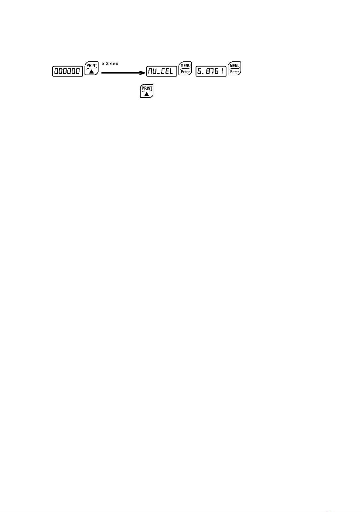
3.1 LOAD CELL INPUT TEST (QUICK ACCESS)
From the weight display, press for 3 seconds; the response signal of the load cells is
displayed, expressed in mV with four decimals.
3.2 LOAD CELL TESTING
Load cell resistance measurement (use a digital multimeter):
Disconnect the load cells from the instrument and check that there is no moisture in the cell
junction box caused by condensation or water infiltration. If so, drain the system or replace it
if necessary.
The value between the positive signal wire and the negative signal wire must be equal or
similar to the one indicated in the load cell data sheet (output resistance).
The value between the positive excitation wire and the negative excitation wire must be
equal or similar to the one indicated in the load cell data sheet (input resistance).
The insulation value between the shield and any other cell wire and between any other cell
wire and the body of the load cell must be higher than 20 Mohm (mega ohms).
Load cell voltage measurement (use a digital multimeter):
Take out the load cell to be tested from underneath the container, or alternatively, lift the
container support.
Make sure that the excitation of two wires of the load cell connected to the instrument (or
amplifier) is 5 Vdc ±3%.
Measure the response signal between the positive and the negative signal wires by directly
connecting them to the tester, and make sure that it is comprised between 0 and ±0.5 mV
(thousandths of a Volt).
Apply load to the cell and make sure that there is a signal increment.
IF ONE OF THE ABOVE CONDITIONS IS NOT MET, PLEASE CONTACT THE
TECHNICAL ASSISTANCE SERVICE.

User manual WTS Ver.1.16
Seite 8von 52
3.3 MAIN SPECIFICATIONS OF THE INSTRUMENT
-Weight indicator and transmitter for Omega/DIN rail mounting suitable for back panel or
junction box. Six-digit semi-alphanumeric display (8mm h), 7 segment. Four-key keyboard.
Dimensions: 25x115x120 mm.
-IP67 box version (170x140x95mm). Four fixing holes diameter 4 mm (centre distance 122x152
mm).
-Displays the gross weight; from external contact allows to zero set or display the net weight
(both values will be lost when the instrument is turned off).
-Peak weight function.
-Transmits the gross or net weight via optoisolated analog output 16 bit, current 0-20mA, 4-
20mA or voltage 0-10V, 0-5V ( ±10V / ±5V by closing a soldering jumper).
-Transmits the gross or net weight via RS485 serial port, by means of protocols:
▫Modbus RTU
▫ASCII bidirectional protocol
▫Continuous transmission

User manual WTS Ver.1.16
Seite 9von 52
4 TECHNICAL SPECIFICATIONS
POWER SUPPLY and CONSUMPTION
(VDC)
12 - 24 VDC +/- 10% ; 5 W
NO. OF LOAD CELLS IN PARALLEL and
SUPPLY
max 8 ( 350 ohm ) ; 5VDC/120mA
LINEARITY / ANALOG OUTPUT LINEARITY
< 0.01% F.S. ; < 0.01% F.S.
THERMAL DRIFT / ANALOG OUTPUT
THERMAL DRIFT
< 0.0005 % F.S. /°C ; < 0.003 % F.S./°C
A/D CONVERTER
24 bit (16.000.000 points)
MAX DIVISIONS (with measurement range:
+/-10mV = sens. 2mV/V)
+/- 999999
MEASUREMENT RANGE
+/- 19.5 mV
MAX SENSITIVITY OF USABLE LOAD
CELLS
+/-3 mV/V
MAX CONVERSIONS PER SECOND
80 conversions/second
DISPLAY RANGE
- 999999 ; + 999999
NO. OF DECIMALS / DISPLAY
INCREMENTS
0 - 4 / x 1 x 2 x 5 x 10 x 20 x 50 x 100
DIGITAL FILTER / READINGS PER
SECOND
10 levels / 5 – 80 Hz
OPTO LOGIC OUTPUTS
N.2 - max 24 VDC ; 60mA
DIGITAL INPUTS
N.2 - optoisolated 5 - 24 VDC PNP
SERIAL PORTS
RS485
BAUD RATE
2400, 4800, 9600, 19200, 38400, 115200
HUMIDITY (non condensing)
85 %
STORAGE TEMPERATURE
- 30°C + 80°C
WORKING TEMPERATURE
- 20°C + 60°C
OPTOISOLATED ANALOG OUTPUT
16 Bit - 65535 divisions
0-20 mA; 4-20 mA (max 300 ohm);
0-10 VDC; 0-5 VDC;
+/- 10 VDC; +/- 5 VDC (min 10 kohm).
OPTO RELAY OUTPUTS
N.2 - max 24 VDC ; 60mA
WORKING TEMPERATURE
-20 °C +60 °C
Equipment to be powered by 12-24 Vdc LPS or Class 2 power source.

User manual WTS Ver.1.16
Seite 10 von 52
IP67 BOX VERSIONS
IP67 box with transparent cover and
six M16x1.5 cable glands
IP67 box with external keypad and
six M16x1.5 cable glands
IP67 box with external keypad and
six M16x1.5 cable glands
And integrated power supply
User manual WTS Ver.1.16
Seite 11 von 52
5 ELECTRICAL CONNECTIONS
5.1 BASIC INFORMATION
-It is recommended that the power supply negative pole be grounded.
-It is possible to supply up to eight 350 ohm load cells or sixteen 700 ohm load cells.
-Connect terminal “0 VDC” to the RS485 common of the connected instruments in the event
that these receive alternating current input or that they have an optoisolated RS485.
-In case of an RS485 network with several devices it is recommended to activate the 120
ohm termination resistance on the two devices located at the ends of the network, as
described in the paragraph RS485 SERIAL CONNECTION.
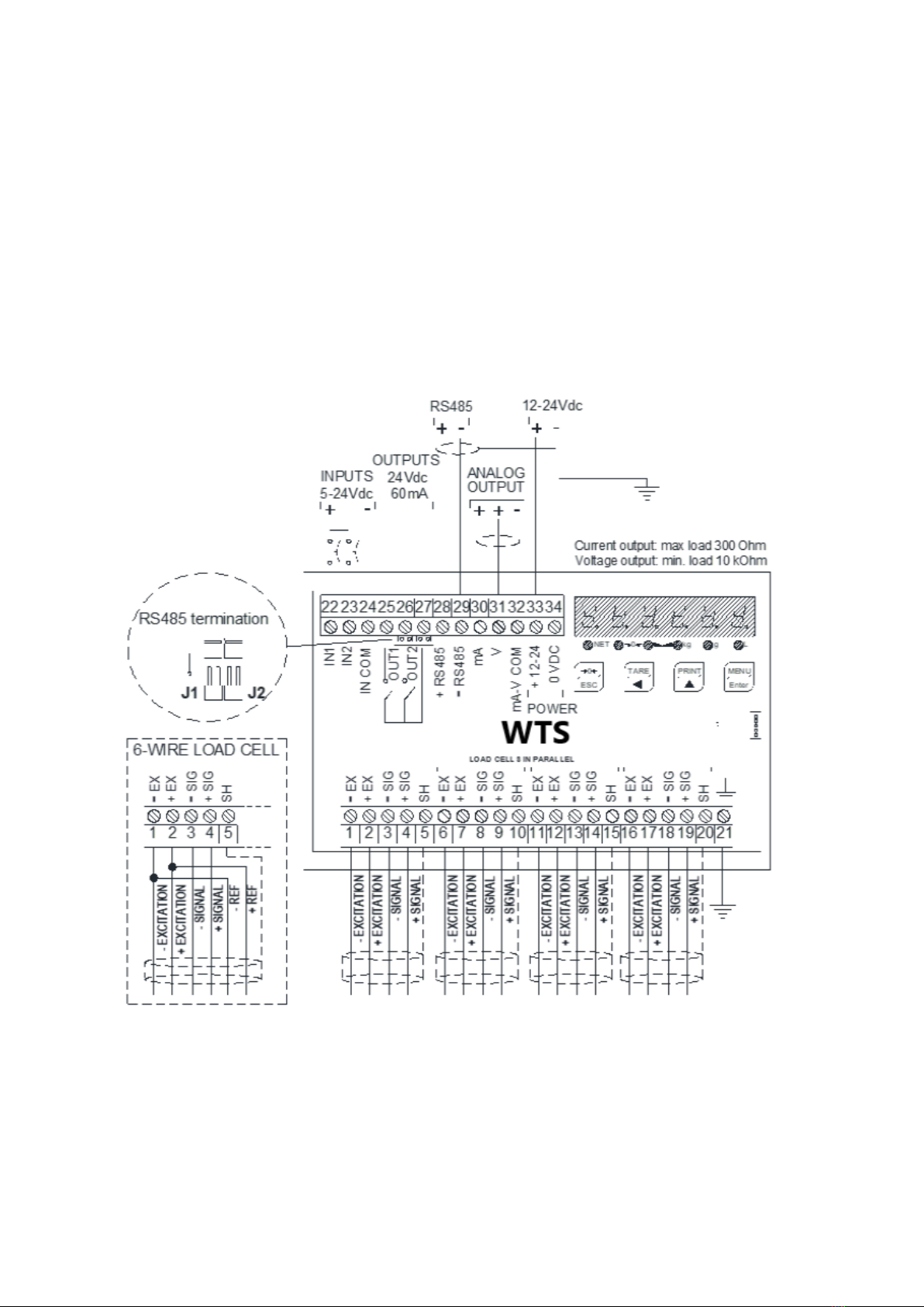
5.2 WIRING DIAGRAM
2 outputs: settable setpoints or remote output management via protocol.
2 inputs (Default: SEMI-AUTOMATIC ZERO input 1; NET/GROSS input 2): settable to
have the following functions: SEMI-AUTOMATIC ZERO, NET/GROSS, PEAK or REMOTE
CONTROL (see paragraph OUTPUTS AND INPUTS CONFIGURATION).
User manual WTS Ver.1.16
Seite 12 von 52
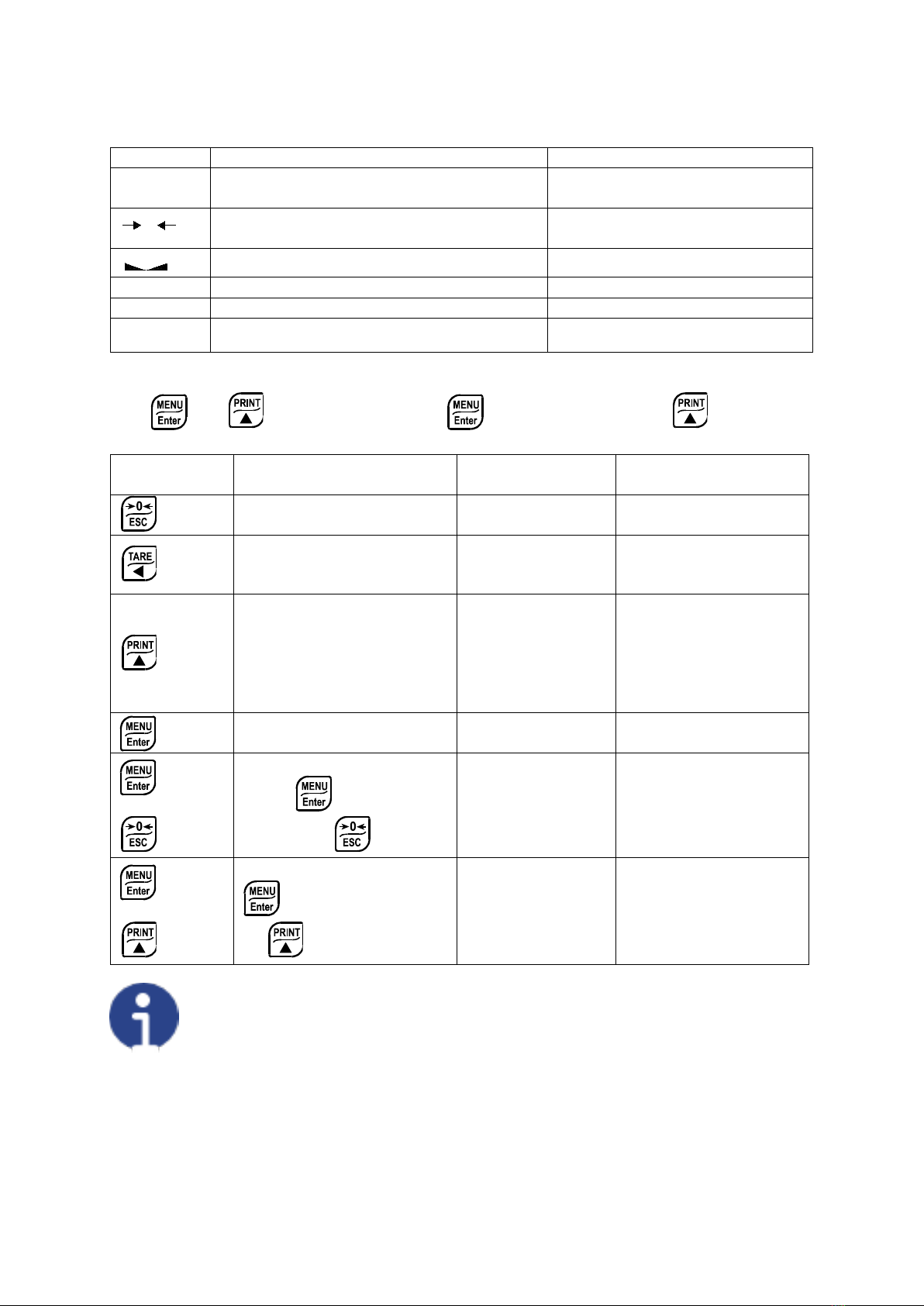
6 LED AND KEY FUNCTIONS
LED
Main function
Secondary function *
NET
net weight LED: net weight display (semi-
automatic tare or preset tare)
LED lit: input 1 closed
zero LED (deviation from zero not more
than +/- 0.25 divisions)
LED lit: input 2 closed
stability LED LED lit: output 1 closed
kg
unit of measure: kg
LED lit: output 2 closed
g
unit of measure: g
no meaning
L other unit of measure no meaning
*) To activate the secondary LED function, during weight display press and hold down the
keys and at the same time (press immediately followed by ).
KEY Short press
Long press
(3 sec)
Into menus
Tare resetting
Cancel or return to
previous menu
Gross Net Net Gross
Select figure to be
modified or return to
previous menu item
Gross weight:
mV load cell test
Net weight:
temporarily display
the gross weight
Modify selected figure
or go to next menu
item
Setting setpoints and
hysteresis
Confirm or enter in
submenu
+
Setting general parameters
(press immediately
followed by )
+
Setting preset tare (press
immediately followed
by )
The LEDs light up in sequence to indicate that a setting and not a weight is being
viewed.
0

User manual WTS Ver.1.16
Seite 13 von 52
7 MENU MAP
Within the menu, the changes are applied immediately after pressing the button (no
further confirmation).
7.1 SETPOINTS
7.2 SYSTEM PARAMETERS
+
3 s
+
3 s

User manual WTS Ver.1.16
Seite 14 von 52
8 INSTRUMENT COMMISSIONING
Upon switch-on, the display shows in sequence:
-instrument model (e.g.: “
”);
-“
” followed by the software code (e.g.:
);
-program type:
(base);
-“
” followed by the software version (e.g.:
);
-“
” followed by the hardware code (e.g.:
);
-the serial number (e.g.:
);
Check that the display shows the weight and that when loading the load cells there is an
increase in weight. If there is not check and verify the connections and correct positioning of
the load cells.
-If the instrument has already been theoretical CALIBRATED (plant system
identification tag present on the instrument and on the cover: load cell’s rated data already
entered):
oReset to zero (follow the procedure in paragraph TARE WEIGHT ZERO SETTING)
oCheck the calibration with sample weights and correct the indicated weight if necessary
(follow the procedure in paragraph REAL CALIBRATION (WITH SAMPLE
WEIGHTS)).
-If the instrument HAS NOT BEEN CALIBRATED (missing plant system identification tag)
proceed with calibration:
oIf load cells data are unknown, follow the procedure in paragraph REAL
CALIBRATION (WITH SAMPLE WEIGHTS)
oEnter the rated data of load cells following the procedure given in paragraph
THEORETICAL CALIBRATION
oReset to zero (follow the procedure in paragraph TARE WEIGHT ZERO SETTING)
oCheck the calibration with sample weights and correct the indicated weight if necessary
(follow the procedure in paragraph REAL CALIBRATION (WITH SAMPLE
WEIGHTS)).
-If you use the analog output, set the desired analog output type and the full scale value
(see paragraph ANALOG OUTPUT).
-If you use serial communication, set the related parameters (see paragraph SERIAL
COMMUNICATION SETTING).
-If setpoints are used, set the required weight values and the relevant parameters (see
paragraphs SETPOINTS PROGRAMMING and OUTPUTS AND INPUTS
CONFIGURATION).
User manual WTS Ver.1.16
Seite 15 von 52
9 PROGRAMMING OF SYSTEM PARAMETERS
From the weight display, press simultaneously keys and to access the parameter
setting.
: to enter a menu/confirm the data entry.
: to modify the displayed value or menu item.
: to select a new value or modify the displayed menu item.
: to cancel and return to the previous menu.
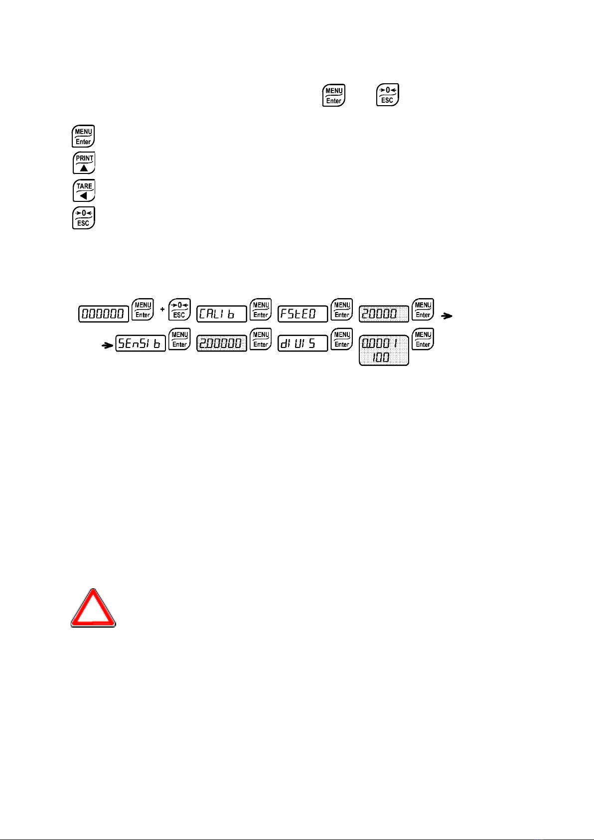
9.1 THEORETICAL CALIBRATION
This function allows the load cell rated values to be set.
To perform the theoretical calibration set the following parameters in sequence:
-
(default:
): the system full scale is given by one cell capacity multiplied by
the number of cells used. Example of system full scale value calculation: 4 cells of 1000kg
FULL SCALE = 1000 X 4 = 4000. The instrument is supplied with a theoretical full scale
value
corresponding to 10000. To restore factory values, set 0 as full scale.
-
(default: 2.00000 mV/V): sensitivity is a load cell rated parameter expressed in mV/V.
Set the average sensitivity value indicated on the load cells. It’s possible to set a value between
0.50000 and 7.00000 mV/V. Example of 4-cell system with sensitivity: 2.00100, 2.00150,
2.00200, 2.00250; enter 2.00175, calculated as (2.00100 + 2.00150 + 2.00200 + 2.00250) / 4.
-
:the division (resolution) is the minimum weight increment value which can be
displayed. It is automatically calculated by the system according to the performed
calibration, so that it is equal to 1/10000 of full scale. It can be changed and be variable
between 0.0001 and 100 with x1 x2 x5 x10 increments.
-By modifying the theoretical full scale or the sensitivity, the real calibration is
cancelled and the theoretical calibration only is considered valid.
-If the theoretical full scale and the recalculated full scale in real calibration (see
section REAL CALIBRATION (WITH SAMPLE WEIGHTS)) are equal, this
means that the calibration currently in use is theoretical; if they are different, the
calibration in use is the real calibration based on sample weights.
-By modifying the theoretical full scale or the sensitivity, the system’s parameters
containing a weight value will be set to default values (setpoint, hysteresis, etc.).
User manual WTS Ver.1.16
Seite 16 von 52
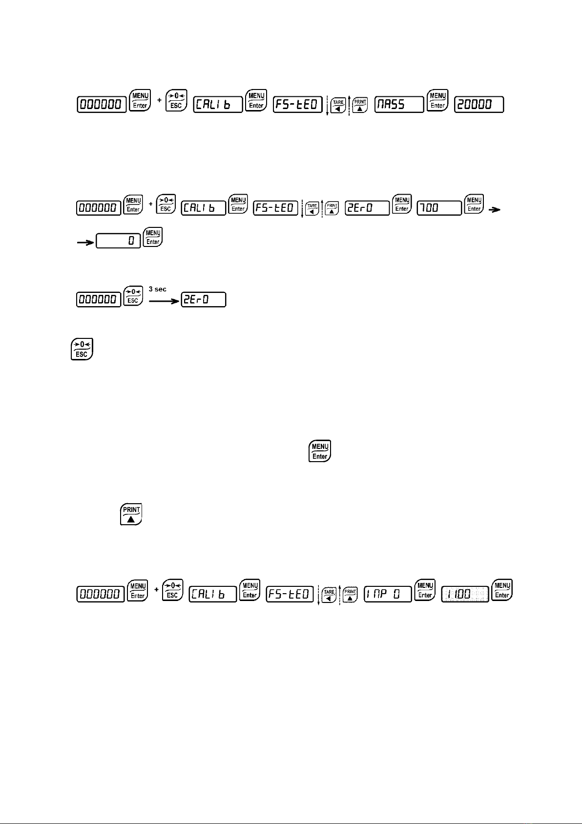
9.1.1 MAXIMUM CAPACITY
: Maximum displayable weight (from 0 to full scale; default: 0). When the weight exceeds
this value by 9 divisions the following is displayed ‘
’. To disable this function, set 0.
9.1.2 TARE WEIGHT ZERO SETTING
This menu may also be accessed directly from the weight display, holding down the
key for 3 seconds.
Perform this procedure after having set the THEORETICAL CALIBRATION data.
Use this function to set to zero the weight of the empty system after commissioning and then
later on to compensate zero variations due to the presence of product residues.
Procedure:
-Confirm the message
(Zero) by pressing .
-The weight value to be set to zero is displayed. In this phase all of the LEDs are flashing.
-Confirming once again, the weight is set to zero (the value is stored to the permanent
memory).
-Press to display the value of the total weight reset by the instrument, given by the
sum of all of the previous zero settings.
9.1.3 ZERO VALUE MANUAL ENTRY
WARNING: Perform this procedure only if it’s not possible to reset the weighed structure
tare, for example because it contains product that can not be unloaded.
Set in this parameter the estimated zero value (from 0 to 999999; default: 0).

User manual WTS Ver.1.16
Seite 17 von 52
9.2 REAL CALIBRATION (WITH SAMPLE WEIGHTS)
After having performed the THEORETICAL CALIBRATION and TARE WEIGHT ZERO
SETTING, this function allows correct calibration to be done using sample weights of
known value, if necessary, any deviations of the indicated value from the correct value
to be corrected.
Load onto the weighing system a sample weight, which must be at least 50% of the maximum
quantity to be weighed.
By confirming the message
the flashing value of the weight currently on the system is
displayed. In this phase all of the LEDs are off. Adjust the value on display by using the arrow
keys if necessary. After confirming, the new set weight will appear with all the LEDs flashing.
After an additional confirmation, the message
will be restored and by repeatedly
pressing the key the weight will once again be displayed.
Example: for a system of maximum capacity 1000 kg and 1 kg division, two sample
weights are available, one of 500 kg and the other one of 300 kg. Load both weights onto
the system and correct the indicated weight to 800. Now remove the 300 kg weight, the
system must show 500; remove the 500 kg weight, too; the system must read zero. If this
does not happen, it means that there is a mechanical problem affecting the system
linearity.
CAUTION: identify and correct any mechanical problems before repeating the
procedure.
-If theoretical full scale and recalculated full scale in real calibration are equal, it
means that the theoretical calibration is currently in use; otherwise, the real
calibration based on sample weights is in use.
-If the correction made changes the previous full scale for more than 20%, all the
parameters with settable weight values are reset to default values.
LINEARISATION OPTION ON MAX 8 POINTS:
It is possible to perform a linearisation of the weight repeating the above-described
procedure up to a maximum of eight points, using eight different sample weights. The
procedure ends by pressing the button or after entering the eighth value; at this
point it will no longer be possible to change the calibration value, but only to perform a new
real calibration. To perform a new calibration, should return to the weight display and then re-
entering into the calibration menu.
By pressing after having confirmed the sample weight that has been set, the full scale
appears, recalculated according to the value of the maximum sample weight entered and
making reference to the cell sensitivity set in the theoretical calibration (
).

User manual WTS Ver.1.16
Seite 18 von 52
9.3 FILTER ON THE WEIGHT
Setting this parameter allows a stable weight display to be obtained.
To increase the effect (weight more stable) increase the value (from 0 to 9, default
4).
As seen in the diagram:
-By confirming the
message, the currently programmed filter value is displayed.
-By changing and confirming the value, the weight is displayed and it will be possible to
experimentally verify its stability.
-If stability is not satisfactory, confirming brings back the message
and the filter may
be modified again until an optimum result is achieved.
The filter enables to stabilise a weight as long as its variations are smaller than the
corresponding “Response Time”. It is necessary to set this filter according to the type of
application and to the full scale value set.
FILTER
VALUE
Response times [ms]
Display and serial port refresh
frequency [Hz]
0
80
80
1
190
80
2
260
40
3
450
26
4 (default)
900
13
5
1700
13
6
2500
13
7
4200
10
8
6000
10
9
7500
5
9.3.1 ANTI PEAK
When the weight is stable, the anti peak filter removes any sudden disturbances with a
maximum duration of 1 second. Confirm the filter on the weight with ENTER and select one
of the following options:
: anti peak filter enabled (default);
: anti peak filter disabled.

User manual WTS Ver.1.16
Seite 19 von 52
9.4 ZERO PARAMETERS
9.4.1 RESETTABLE WEIGHT SETTING FOR SMALL WEIGHT CHANGES
(from 0 to full scale; default: 300; considered decimals: 300 – 30.0 – 3.00 – 0.300): this
parameter indicates the maximum weight value resettable by external contact, keypad or serial
protocol.
9.4.2 AUTOMATIC ZERO SETTING AT POWER-ON
(from 0 to 10% of full scale; default: 0): If at switch-on the weight value is lower than
the value set in this parameter, the weight is reset.To disable this function, set 0.
9.4.3 ZERO TRACKING
(from 1 to 5, default:
): When the zero weight value is stable and, after a
second, it deviates from zero by a figure in divisions smaller or equal to the figure in divisions
set in this parameter, the weight is set to zero. To disable this function, set
.
Example: if the parameter
is set to 5 and
is set to 2, the weight will be
automatically set to zero for variations smaller than or equal to 10 (
x
).

User manual WTS Ver.1.16
Seite 20 von 52
9.5 SETTING UNITS OF MEASURE
Available unit of measure are:
: kilograms
: grams
: tons
: pounds*
: newton*
: litres*
: bar*
: atmospheres*
: pieces*
: newton metres*
: kikogram metres*
: other generic units of measure not included in the list*
If the print function is enabled, the symbol corresponding to the selected unit of measure will
be printed after the measured value.
For the units marked with * it’s possible to set also the display coefficient
(parameter
, see the related paragraph). To use
is necessary to
enable it, closing the
input (see paragraph OUTPUTS AND INPUTS
CONFIGURATION).
9.5.1 DISPLAY COEFFICIENT
By setting the coefficient
the display is changed accordingly.
If one of the inputs is set to
mode (see paragraph OUTPUTS AND INPUTS
CONFIGURATION) when the input is closed the value will be displayed modified according to
the
coefficient; when the input is opened the standard weight display will be restored.
: (max settable value: 99.9999; default: 1.0000) will have different meanings according to the
value set in
, i.e. the selected unit of measure. (see paragraph SETTING UNITS OF
MEASURE).
Table of contents
Other Bosche Measuring Instrument manuals


