1
CONTENTS
Safety Information.............................................................................................................................2
Warranty .............................................................................................................................................2
Product Description ..........................................................................................................................3
Carton Contents ................................................................................................................................3
Amplifier Rear Panel Connections and Controls ...........................................................................4
Top Panel Indicators .........................................................................................................................4
Setting Up a Single A1 Amplifier .....................................................................................................5
Using Multiple A1 Amplifiers ............................................................................................................6
Using the A1 in other applications ..................................................................................................7
Setting up the A1 for use with other systems: ...............................................................................7
Specifications ....................................................................................................................................8
Production Notes ..............................................................................................................................9
Electrostatic Discharge Sensitive (ESDS) Device Handling .........................................................9
Part List Notes ...................................................................................................................................9
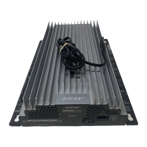
Packaging Part List, PackLiteTM A1 Amplifier Assembly (see Figure 1) .....................................10
Figure 1. PackLite A1 Amplifier Assembly Packaging View............................................................10
Main Part List, PackLite A1 Amplifier Assembly (see Figure 2) .................................................. 11
Figure 2. PackLite A1 Amplifier Exploded View ..............................................................................12
Electrical Part Lists ................................................................................................................... 13-29
Power Supply / Amplifier PCB Assembly................................................................................ 13-22
Input / Limiter PCB Assembly .................................................................................................. 23-28
Signal LED PCB Assembly .............................................................................................................29
Power / Fault LED PCB Assembly .................................................................................................29
Disassembly Procedures ......................................................................................................... 30-33
Test Procedures ........................................................................................................................ 33-34
Figure 3. Amplifier/SMPS PCB (Non-RoHS) Topside Etch Layout .................................................35
Figure 4. Amplifier/SMPS PCB (Non-RoHS) Internal Etch Layer 1 Layout ....................................35
Figure 5. Amplifier/SMPS PCB (Non-RoHS) Internal Etch Layer 2 Layout ....................................36
Figure 6. Amplifier/SMPS PCB (Non-RoHS) Bottom Etch Layout ..................................................36
Figure 7. Amplifier/SMPS PCB (RoHS) Topside Etch Layout .........................................................37
Figure 8. Amplifier/SMPS PCB (RoHS) Internal Etch Layer 1 Layout ............................................37
Figure 9. Amplifier/SMPS PCB (RoHS) Internal Etch Layer 2 Layout ............................................38
Figure 10. Amplifier/SMPS PCB (RoHS) Bottom Etch Layout........................................................38
Figure 11. Input/Limiter PCB (Non-RoHS) Top Side Etch Layout ...................................................39
Figure 12. Input/Limiter PCB (Non-RoHS) Bottom Side Etch Layout .............................................39
Figure 13. Input/Limiter PCB (RoHS) Top Side Etch Layout ..........................................................40
Figure 14. Input/Limiter PCB (RoHS) Bottom Side Etch Layout.....................................................40
Figure 15. Power/Fault LED PCB Etch Layout ...............................................................................41
Figure 16. Signal/Overload LED PCB Etch Layout ........................................................................41
Test Cable Wiring Diagrams...........................................................................................................41
Troubleshooting ..............................................................................................................................42
Theory of Operation, PackLite Model A1 Amplifier ................................................................ 43-50
Integrated Circuit Diagrams ..................................................................................................... 51-53
Service Manual Revision History...................................................................................................54
