©2000 Bose Corporation
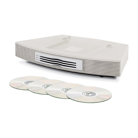
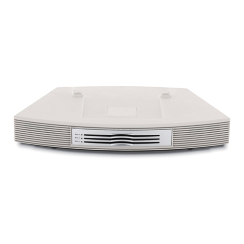
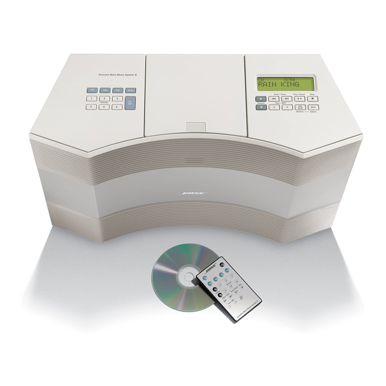
BOSE® WAVE® RADIO/CD TROUBLESHOOTING GUIDE
Refer to the Bose Wave radio/CD service manual, part number 25044 , for schematics,
PCB layouts and part lists.
Part Number 25044 -TG1 Rev. 00
Symptom Reason(s) A tion
Dead Unit. 1. Fuse F1 open.
2. Unseated J1.
. Open power transformer.
1. Replace fuse F1.
2. Reconnect J1.
. Replace power transformer.
Unit turns on/off by
itself. CD door defective. Replace the CD door assembly.
Intermittent or
inoperable FM/AM.
Depending on date code,
defective CF 0 and C 41, C 42
or fractured solder joints on
CF 0 .
Refer to service bulletin 25044 -
B for further information.
1. In units built before 5/4/99,
replace CF 0 with a 7.2 MHz
crystal, part number 250892-
001 and C 41 and C 42 with
27pF capacitors part number
1 622-270. After soldering
CF 0 , be sure to clip the
leads.
2. In units built after 5/4/99,
check for fractured solder
joints on CF 0 and make
sure the leads have been
clipped.
Constant hum on
AM/FM. Power supply capacitor C205 may
be installed with reverse polarity. Replace capacitor C205 part
number 144000-471V.
Hum on all sources. Reversed C202 or C205. Replace C202 or C205.
The CD player is
inoperable or
intermittent.
Fractured solder joints on power
supply capacitor C16. Re-solder power supply capacitor
C16.
The unit doesn’t
respond to the
buttons located on
the CD door.
The PCB located in the CD door
assembly may be cracked. Replace the CD door assembly,
part number 198608-010 platinum
white or 198608-002 graphite
grey.
CD does not work. 1. CD mechanism lens dirty.
2. C16 has fractured solder joints
. 1 conductor flex cable
defective.
4. CD mechanism failed.
5. U500 defective.
6. Switch on CD door assembly
defective.
1. Clean lens.
2. Resolder C16.
. Replace the flex cable.
4. Replace the CD mechanism.
5. Replace U500.
6. Replace the CD door
assembly.
CD skips. 1. C16 has fractured solder joints
2. 1 conductor flex cable
defective.
1. Resolder C16.
2. Replace the flex cable.
