BOSSCO AX1-2.5E Manual

Operation &
Maintenance Manual
BOSS Digital Pressurisation Equipment
AX Models (AX1-2.5E, AX2-2.5E, AX1-5E, AX2-5E)
PF Models (PF1-2.5E, PF2-2.5E, PF1-5E, PF2-5E)
Midi Models (MD1-2.5E, MD2-2.5E, MD1-5E, MD2-5E)
Digifiller (Digifiller 0.5, Digifiller 1.0, Digifiller 1.5, Digifiller 2.0)
Mini Models (MX1-3E, MX2-3E)

2
Contents
About this Manual 3
Conventions used in this Manual 3
Typography 3
Where to find more Information 3
Equipment Overview 4
Principal of Operation 4
Installation 5
Pipe Connections 5
Typical Installation Diagram 5
Flow Restrictors (Midi & Mini models only) 6
AX Skid Clearance and Connection Requirements 7
Pressfill (PF) Clearance and Connection Requirements 8
Midi (MD) Clearance and Connection Requirements 9
Mini (MX) Clearance and Connection Requirements 10
Electrical Power Supply 11
Fault Contacts 12
Power Filter 13
Commissioning 14
Pre-Commissioning Checklist 14
Controller Overview 15
Controller Programming 16
Hydraulic Commissioning 20
Commissioning Record 25
Operation 26
Fault Codes 26
Shutdown Procedure 27
Start-Up Procedure 27
Troubleshooting 28
Maintenance 31
Wiring Diagram 33
Service Log 34
Spares 36
Electrical Items (All Models) 36
AX Models (AX1-2.5E, AX2-2.5E, AX1-5E, AX2-5E) 37
PF Models (PF1-2.5E, PF2-2.5E, PF1-5E, PF2-5E) 38
Midi Models (MDE1-2.5, MDE2-2.5, MDE1-5, MDE2-5) 39
Digifiller Models (Digifiller 0.5, Digifiller 1.0, Digifiller 1.5, Digifiller 2.0) 39
Mini Models (MX1-3E, MX2-3E) 40

3
About this Manual
This Operation and Maintenance Manual contains all the necessary information to install,
commission, operate and maintain pressurisation equipment.
It is recommended to read all parts of this manual before undertaking any work on the equipment.
Conventions used in this Manual
This manual makes use of symbols to identify key pieces of information. Please take note of the
following symbols and their meaning:
DANGER –Important safety related information intended to prevent injury and/or
damage to the equipment, system or property.
CAUTION - Important information intended to prevent damage to the equipment,
system or property.
IMPORTANT - Important information intended to ensure that the equipment functions
correctly.
USEFUL –Useful information which may be helpful, but is not necessarily required for
the unit to function correctly.
Typography
This manual makes use of different typography to identify different types of information.
Italics Key words and phrases
(Round Brackets) Used to identify a button on the digital controller
[Square Brackets] A parameter on the digital controller
<Inequality Symbols> A message/fault code displayed on the digital controller
Where to find more Information
For further information please visit the BSS Website at: http://www.bssindustrial.co.uk/
BSS Technical (Leicester)
AMS Wigan
AMS Spares & Service (Nottingham)
Tel: 0116 262 3232
Tel: 0870 609 2101
Tel: 0870 850 3886
Email: enquires@bssgroup.com
Email: amspumps@bssgroup.com
Email: amsse@bssgroup.com
4
Equipment Overview
The function of this pressurisation unit is to provide a means of automated water top-up to sealed
heating and cooling systems. The equipment is designed to provide periodic water top-up to
compensate for minor losses in system pressure (e.g. slow leaks, air venting, etc.).
This equipment is not designed to cope with sudden losses of system pressure (e.g.
manual draining) or major water losses (e.g. large leaks). The equipment is also not
intended to be used for water boosting applications.
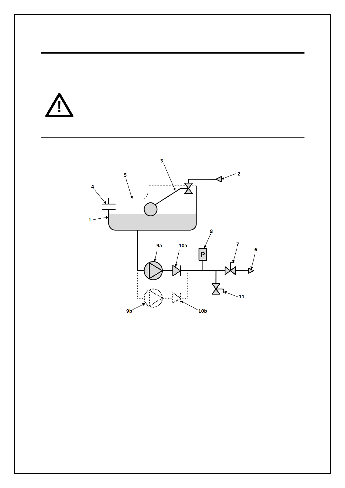
Principal of Operation
The following schematic shows the internal arrangement of a pressurisation unit:
The pressurisation unit is fitted with a break tank (1) which is filled from the mains water supply (2)
via a float operated valve (3). The break tank is fitted with an overflow (4) in case the break tank
overfills, and a weir overflow (5) in case the primary overflow fails.
The pressurisation unit is connected into the heating system (6) via an isolation valve (7).
The pressure sensor (8) monitors the system pressure.
If the pressure sensor detects a drop in pressure, the pump (9a) will pump water from the break tank
into the system. Once the required pressure has been reached, the pump will stop.
On twin pump models, a second pump (9b) is provided. The two pumps will run in a duty/standby
configuration (i.e. the active pump will alternate with each pump start).
The pump(s) are fitted with non-return valves (10a, 10b) to prevent backflow.
A drain valve (11) is provided for draining down the unit and for commissioning purposes.

5
Installation
This pressurisation unit is not designed to be installed in an outdoor environment. The
unit must be installed in a frost free environment, away from precipitation and water
sprays/jets. If there is a risk of flooding, the unit must be installed on a raised plinth.
Please refer to the appropriate datasheet for the maximum working pressure and
temperature of the pressurisation unit. The conditions at the point of connection to
the system must not exceed these values.
Pipe Connections
To avoid damaging the float valve, the mains water supply pipe must be flushed before
connection to the pressurisation unit.
All pipe connections must be made with appropriate jointing compound/PTFE tape.
If PTFE tape is used, care must be taken to ensure that the tape does not obstruct the
orifice of the fitting.
Non-return valves, pressure reducing valves and RPZ valves must not be installed
between the pressurisation unit and the heating/cooling system. These devices will
prevent the pressure sensor from reading the system pressure.
The pressurisation unit and expansion vessel should be connected to the system at the
same point, to provide a neutral pressure reading. This point of connection should be
in the system return, on the suction side of the circulation pump.
Typical Installation Diagram
This manual suits for next models
17
Table of contents
Other BOSSCO Industrial Equipment manuals


