BOSSCO DM-101 User manual

DM-101
Reference Manual

Table of contents
2
Table of contents
Panel Descriptions ................................................................................................................................................................................................3
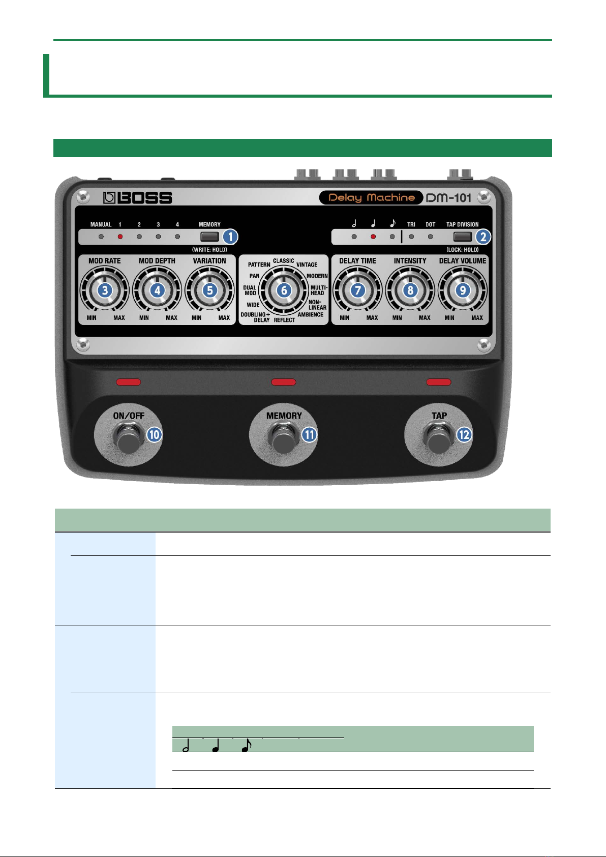
Top Panel.............................................................................................................................................................................................................. 3
Rear Panel ............................................................................................................................................................................................................ 5
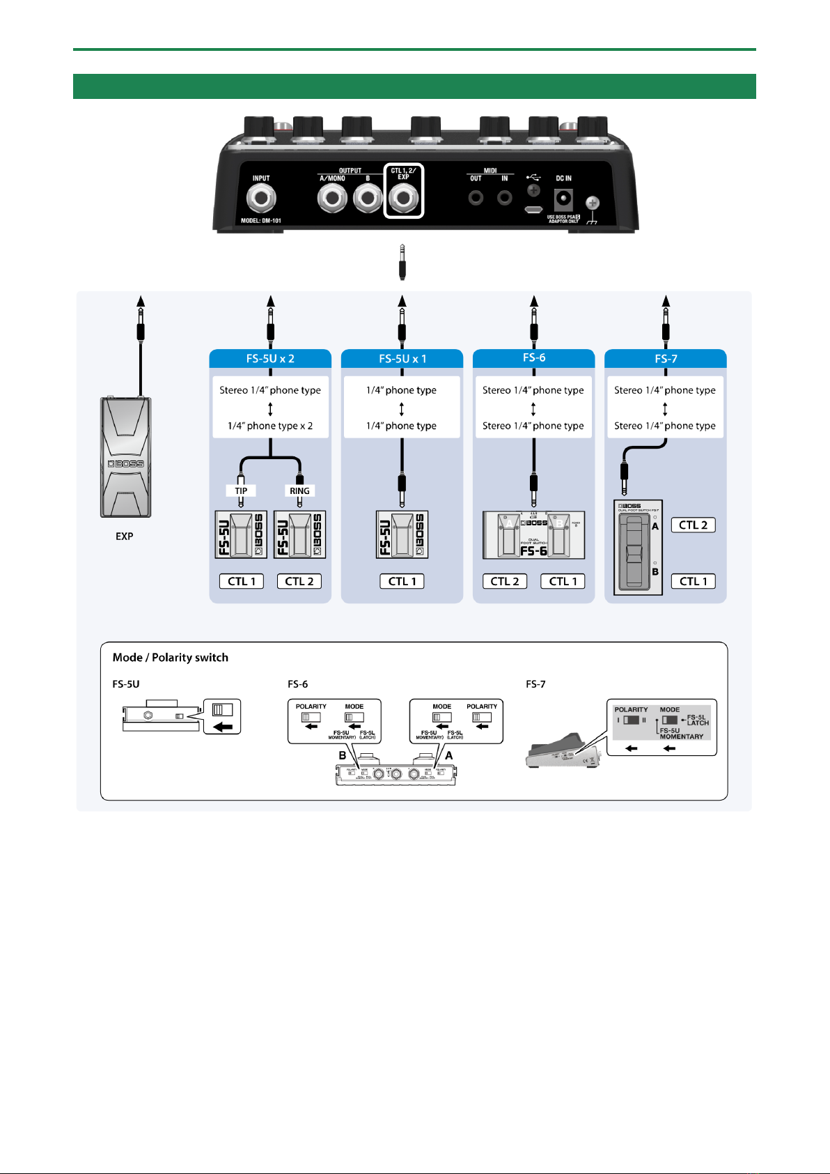
Connecting External Pedals ............................................................................................................................................................................... 6
Turning the Power On/Off.................................................................................................................................................................................. 7
Mode List.............................................................................................................................................................................................................. 8
Saving and Switching Between Memories................................................................................................................................................10
Various Settings ...................................................................................................................................................................................................11
Setting the Expression Pedal Function........................................................................................................................................................... 11
Setting the Footswitch Functions (CTL 1 FUNCTION, CTL 2 FUNCTION)..................................................................................................... 12
Switches Between Output Modes ................................................................................................................................................................... 13
Preserving/Muting the Tail of an Effect when the Effect is Switched Off (CARRYOVER) .......................................................................... 14
Setting the Maximum Value of MEMORY (MEMORY EXTENT) ..................................................................................................................... 15
MIDI Settings ..................................................................................................................................................................................................... 16
Restoring the Factory Default Settings (Factory Reset)........................................................................................................................19
Attaching the Rubber Feet ..............................................................................................................................................................................20
Main Specifications.............................................................................................................................................................................................21

Panel Descriptions
3
Panel Descriptions
Top Panel
Name
Function
1
[MEMORY] button
Switches between or saves memories (MANUAL, 1–4).
MEMORY
indicators
Indicates the currently selected memory.
When MIDI is used to select memories 5–127, all indicators go dark.
*If you turn the [VARIATION] knob while the mode is MULTI-HEAD, MEMORY indicators 1–4
indicate the head pattern you selected. The indicators return to the normal memory display after
a little while.
2
[TAP DIVISION]
button
Specifies the delay time in terms of a note length relative to the BPM.
Preventing accidental operation (panel lock)
By long-pressing the [TAP DIVISION] button, you can switch between enabling (unlocking) or
disabling (locking) the knobs and buttons.
If you try to operate the knobs and buttons while they’re locked, the TAP DIVISION indicator blinks.
TAP DIVISION
indicator
This indicates the delay time as a note value; the interval at which you press the pedal is considered as
a quarter note (100%).
TAP DIVISION indicator
Explanation
TRI
DOT
µ
µ
Dotted half note (300%)
µ
Half note (200%)

Panel Descriptions
4
Name
Function
µ
µ
Dotted quarter note (150%)
µ
µ
Half-note triplet (133%)
µ
Quarter note (100%)
µ
µ
Dotted eighth note (75%)
µ
µ
Quarter-note triplet (67%)
µ
Eighth note (50%)
µ
µ
Eighth-note triplet (33%)
*Not supported in some delay modes. For details, refer to “1.5. Mode List(P.8)”.
3
[MOD RATE] knob
Adjusts the modulation rate of the delay sound.
4
[MOD DEPTH] knob
Adjusts the modulation depth of the delay sound.
5
[VARIATION] knob
Adjusts the tonal character of the delay sound.
The effect differs depending on the mode. See the “1.5. Mode List(P.8)” for details.
6
Mode knob
Selects the delay mode (type).
1.5. Mode List(P.8)
7
[DELAY TIME] knob
Adjusts the delay time.
Turning the knob toward the right increases the delay time.
8
[INTENSITY] knob
Adjusts the number of delay repeats.
Turn this knob toward the right to increase the number of repeats. If you turn the knob all the way to
the left, a single delay is heard.
*If you turn the knob all the way to the right, oscillation might occur.
9
[DELAY VOLUME]
knob
Adjusts the volume of the delay sound.
Turn this knob toward the right to increase the delay sound. If you turn the knob all the way to the left,
only direct sound is heard.
10
[ON/OFF] switch
Turns the delay on/off.
11
[MEMORY] switch
Press to switch between memories.
12
[TAP] switch
By pressing the switch at the tempo of the song you’re performing, this lets you specify a matching
delay time.
If the tempo is lower than the minimum delay time, the delay time is set to 1/2 and 1/4 of the tempo.
If the tempo is higher than the maximum delay time, the delay time is set to two and four times the
tempo.
*Not supported in some delay modes. For details, refer to “1.5. Mode List(P.8)”.

Panel Descriptions
5
Rear Panel
Name
Function
13
INPUT jack
Connect your electric guitar, keyboard, or other musical instruments and effect units to this input
jack.
14
OUTPUT A/MONO, B
jacks
Connect your guitar amp, keyboard amp, other effect units or your mixer here.
For mono output, connect to the A/MONO jack.
15
CTL1, 2/EXP jack
●
Using the jack as CTL 1, 2
You can connect a footswitch (FS-5U, FS-6, FS-7; sold separately) to switch MEMORY UP/DOWN and so on.
●Using the jack as EXP
Connect an expression pedal (EV-30, Roland EV-5, etc.; sold separately) to continuously change the effect
settings for the expression pedal’s pushed-up (horizontal) position and for the pushed-down (slanted)
position.
16
MIDI IN/OUT
connectors
Use TRS/MIDI connecting cables (BMIDI-5-35, BMIDI-1-35, BCC-1-3535; sold separately) to connect
this unit to an external MIDI device.
You can use an external MIDI device to switch between up to 128 memories on this unit.
*Do not use these connectors for connecting to audio devices. Doing so may cause a
malfunction.
17
USB port
Connect your computer using a commercially available USB cable that supports USB 2.0.
*Do not use a micro USB cable that is designed only for charging a device. Charge-only cables
cannot transmit data.
*Used only for updating programs.
18
DC IN jack
Connect the AC adaptor to this jack.
Use only the specified AC adaptor (PSA-series), connected to a 100 V AC power source.
When you connect the included AC adaptor to the DC IN jack, the unit turns on.
1.4. Turning the Power On/Off(P.7)
19
Ground terminal
Connect this to an external earth or ground. This should be connected when necessary.
*To prevent malfunction and equipment failure, always turn down the volume, and turn off all the units before making any
connections.

Panel Descriptions
6
Connecting External Pedals

Panel Descriptions
7
Turning the Power On/Off
Once everything is properly connected, be sure to follow the procedure below to turn on their power. If you turn on equipment in
the wrong order, you risk causing malfunction or equipment failure.
*Before turning the unit on/off, always be sure to turn the volume down. Even with the volume turned down, you might hear
some sound when switching the unit on/off. However, this is normal and does not indicate a malfunction.
Turning the Power On
Turn on the power to your amp last.
Turning the Power Off
Turn off the power to your amp first.

Panel Descriptions
8
Mode List
Mode
Explanation
Delay time
MIDI SYNC
support for
[TAP] switch
[VARIATION] knob function
CLASSIC
A sound with a warmth
that’s characteristic of
analog delays.
40–1,200 ms
µ
Adjusts the modulation waveform.
The MIN setting produces a triangle wave,
the center setting produces a sine wave;
and the closer you get to the MAX setting,
the more complex the waveform becomes.
VINTAGE
Simulates the sound of the
BOSS DM-2.
10–300 ms
µ
MODERN
Produces a clear delay
sound with a distinct high
end.
40–840 ms
µ
MULTI-
HEAD
Produces a deep echo-like
effect.
20–300 ms
µ
Selects the head pattern (delay pattern) (10
types). (*1, *2)
When you turn the knob, MEMORY
indicators 1–4 indicate the head pattern
you selected.
The indicators return to the normal
memory display after a little while.
NON-
LINEAR
A delay that gives a
reversed effect.
35–190 ms
Adjusts the volume for each delay interval.
AMBIENCE
A sound that simulates a
very narrow space.
VARIATION (Early
reflection) MIN:
140–160 ms
VARIATION (Early
reflection) MAX:
290–400 ms
Adds the sounds of early reflections.
REFLECT
Produces a reverb-like
effect.
90–320 ms
Produces a pre-delay effect (40–290 ms).
DOUBLING+
DELAY
Produces a short doubling
delay that adds thickness
to the sound, along with
the reflection sound.
10–310 ms
µ
Adjusts the doubling delay time (10–20
ms).
WIDE
Shifts the respective
OUTPUT A/B delay times to
create a more expansive
sound.
25–590 ms
µ
Adjusts the time difference for the OUTPUT
A/B delay time.
DUAL MOD
Gives a modulation effect
with different phases for
OUTPUT A/B.
110–600 ms
µ
Adjusts the modulation phase for OUTPUT
A/B. The MAX setting inverts the phase for
OUTPUT A/B.
PAN
A stereo tap delay that
outputs the delay sound
with different timings for
OUTPUT A/B.
20–450 ms
µ
Adjusts the time difference for the OUTPUT
A/B delay time.
PATTERN
Creates a rhythmic delay
effect.
VARIATION (Pattern) 1:
50–300 ms
VARIATION (Pattern) 2:
60–300 ms
VARIATION (Pattern) 3:
60–300 ms
VARIATION (Pattern) 4:
40–190 ms
VARIATION (Pattern) 5:
30–190 ms
VARIATION (Pattern) 6:
50–300 ms
VARIATION (Pattern) 7:
60–290 ms
VARIATION (Pattern) 8:
20–80 ms
VARIATION (Pattern) 9:
60–300 ms
VARIATION (Pattern) 10:
60–300 ms
µ
Selects the delay pattern (10 types). (*1)

Panel Descriptions
9
(*1) You can switch between patterns 1–10 by changing the knob position.
(*2) The contents of head patterns 1–10 are shown below.
Head pattern
1
2
3
4
5
6
7
8
9
10
Playback head 1
Á
Á
Á
Á
Á
Á
Á
Playback head 2
Á
Á
Á
Á
Á
Á
Playback head 3
Á
Á
Á
Á
Á
Á
Á
Playback head 4
Á
Á
Á
Á
Á
Á

Saving and Switching Between Memories
10
Saving and Switching Between Memories
Saving to a Memory
You can save the settings you’ve edited.
1.
Long-press the [MEMORY] button.
The indicator of the currently selected memory number blinks, and the memory enters write standby mode.
2.
Take your finger off the [MEMORY] button.
3.
Press the [MEMORY] button to select where to save the memory.
Each time you press the button, the memory selector cycles through as follows: MANUALÓ1Ó2Ó3Ó4.
You can use an external MIDI device to select memories 5–127. When you select memories 5–127, the MEMORY 1–4 indicators
all blink.
4.
Long-press the [MEMORY] button once more to save.
The memory number indicators blink rapidly. Once they remain lit, the write operation is finished.
When using an external MIDI device to select memories 5–127, the MEMORY 1–4 indicators all blink rapidly and then go dark.
*If you operate the knobs or footswitch before step 3, the write operation is canceled.
*If you’ve saved to MANUAL, only the [TAPE] button and expression pedal settings are saved.
Switching Memories
Here’s how to recall a saved memory.
1.
Press the [MEMORY] button or [MEMORY] switch to select the memory.
Each time you press the button/switch, the memory selector cycles through as follows: MANUALÓ1Ó2Ó3Ó4.
You can use an external MIDI device to select memories 5–127 via MIDI. When you select memories 5–127, the MEMORY 1–4
indicators all go dark.
What is “MANUAL”?
Normally, effects are applied according to the settings in memory. However, when you select MANUAL, effects are applied
according to the position of the knobs on the panel. At this time, the TAP DIVISION and expression pedal settings that are recalled
are those saved in MANUAL (which are editable).

Various Settings
11
Various Settings
Setting the Expression Pedal Function
By connecting an expression pedal (such as the EV-30, sold separately) to the CTL 1, 2/EXP jack, you can operate the top panel
knobs except for the Mode knob.
You can set the respective sounds for when the expression pedal is at MAX position (pushed all the way up with your toes) and at
MIN position (pushed all the way down with your heel), and make continuous changes to them.
You can use different expression pedal settings for MANUAL and for each memory in MEMORY 1–4 respectively.
You can also set and add a different function to the functions you’ve already set. This lets you create settings that operate multiple
knobs at once.
1.
Use the [MEMORY] button to select the memory (MANUAL, MEMORY 1–4) for which you want to
configure the expression pedal.
2.
Hold down the [TAP] switch and press the [TAP DIVISION] button.
The TRI indicator blinks
3.
Use the respective knobs to set the sound that’s used when the pedal is at the MIN value (pushed all the
way down with your heel).
4.
Press the [TAP DIVISION] button again.
The DOT indicator blinks.
5.
Use the respective knobs to set the sound that’s used when the pedal is at the MAX value (pushed all the
way up with your toes).
6.
Press the [TAP DIVISION] button again to exit the function settings.
If you want to clear the function settings for the expression pedal, go through steps 1 to 6 above without operating any knobs
in steps 3 and 6.
●
To save the expression pedal function settings, you must save the memory.
●Use only the specified expression pedal. Connecting expression pedals made by third-party manufacturers may
cause this unit to malfunction.

Various Settings
12
Setting the Footswitch Functions (CTL 1 FUNCTION, CTL 2 FUNCTION)
Here’s how to configure the functions of the footswitch connected to the CTL 1, 2/EXP jack (FS-5U, FS-6, FS-7; sold separately).
1.
Press and hold down the [TAP] switch, and turn on the power.
2.
Set the Mode knob to “CLASSIC” if you wish to set the CTL 1 function, or to “VINTAGE” if you wish to set
the CTL 2 function.
3.
Use the [MEMORY] button to select the function to set.
MEMORY indicators
Function
MANUAL
Select the next memory.
1
Select the previous memory.
2
Turn on/off effects.
3
Press the footswitch at the tempo of the song you’re playing to specify a matching delay time.
4.
Press the [TAP] switch to exit the function settings.

Various Settings
13
Switches Between Output Modes
You can change how the output works by switching between output modes.
You can turn the output of the direct sound off when you want to output only the effect’s sound, such as when you’re connecting
this unit to the send/return of a mixer.
1.
Press and hold down the [TAP] switch, and turn on the power.
2.
Turn the Mode knob to the “MODERN” setting.
3.
Use the [MEMORY] button to select the output mode.
MEMORY
indicators
Output mode
Function
MANUAL
NORMAL
When a plug is inserted into the OUTPUT A/B jacks:
The effect sound (L ch) + direct sound is output from the OUTPUT A jack, and the
effect sound (R ch) + direct sound is output from the OUTPUT B jack.
When a plug is inserted into the OUTPUT A jack only:
The effect sound and direct sound are output.
1
DIRECT/EFFECT
When a plug is inserted into the OUTPUT A/B jacks:
The effect sound (L ch + R ch) is output from the OUTPUT A jack, and the direct
sound is output from the OUTPUT B jack.
When a plug is inserted into the OUTPUT A jack only:
The effect sound (L ch + R ch) is output from the OUTPUT A jack.
2
DIRECT MUTE
Turns the direct sound output off.
When a plug is inserted into the OUTPUT A/B jacks:
The effect sound (L ch) is output from the OUTPUT A jack, and the effect sound (R
ch) is output from the OUTPUT B jack.
When a plug is inserted into the OUTPUT A jack only:
The effect sound (L ch + R ch) is output from the OUTPUT A jack.
4.
Press the [TAP] switch to exit the function settings.

Various Settings
14
Preserving/Muting the Tail of an Effect when the Effect is Switched Off
(CARRYOVER)
This sets whether to preserve (carry over) the tail of an effect after the effect is switched off.
1.
Press and hold down the [TAP] switch, and turn on the power.
2.
Turn the Mode knob to the “MULTI-HEAD” setting.
3.
Use the [MEMORY] button to select the setting.
MEMORY indicators
Function
MANUAL
Reverberation carries over
1
Reverberation does not carry over
4.
Press the [TAP] switch to exit the settings.
●
This is only supported when the effect is turned on/off. This is not supported when switching between memories.
●If this function is set to carry over the effect, the self-oscillation of the effect continues to be output, even if the effect
is turned off while the effect sound is self-oscillating. To stop the self-oscillating sound, turn the [INTENSITY] knob all
the way down.

Various Settings
15
Setting the Maximum Value of MEMORY (MEMORY EXTENT)
Here’s how to set the maximum value for the selectable memories.
1.
Press and hold down the [TAP] switch, and turn on the power.
2.
Turn the Mode knob to the “NON-LINEAR” setting.
3.
Use the [MEMORY] button to set the maximum value.
MEMORY indicators
Maximum Value
1
1
2
2
3
3
4
4
4.
Press the [TAP] switch to exit the settings.

Various Settings
16
MIDI Settings
1.
Press and hold down the [ON/OFF] switch, and turn on the power.
2.
Turn the Mode knob to select the parameter to set.
3.
Use the [MEMORY] button to select the setting.
4.
Press the [ON/OFF] switch to exit the settings.
Setting
Mode knob
Value
Indicators that are lit
Explanation
Receive channel
(RX CH)
CLASSIC
OFF
MEMORY: MANUAL
TAP DIVISION:
Off
1
MEMORY: 1
TAP DIVISION:
CH. 1
2
MEMORY: 2
TAP DIVISION:
CH. 2
3
MEMORY: 3
TAP DIVISION:
CH. 3
4
MEMORY: 4
TAP DIVISION:
CH. 4
5
MEMORY: MANUAL
TAP DIVISION:
CH. 5
6
MEMORY: 1
TAP DIVISION:
CH. 6
7
MEMORY: 2
TAP DIVISION:
CH. 7
8
MEMORY: 3
TAP DIVISION:
CH. 8
9
MEMORY: 4
TAP DIVISION:
CH. 9
10
MEMORY: MANUAL
TAP DIVISION:
CH. 10
11
MEMORY: 1
TAP DIVISION:
CH. 11
12
MEMORY: 2
TAP DIVISION:
CH. 12
13
MEMORY: 3
TAP DIVISION:
CH. 13
14
MEMORY: 4
TAP DIVISION:
CH. 14
15
MEMORY: MANUAL
TAP DIVISION: TRI
CH. 15
16
MEMORY: 1
TAP DIVISION: TRI
CH. 16
Transmit channel
(TX CH)
VINTAGE
OFF
MEMORY: MANUAL
TAP DIVISION:
Off
1
MEMORY: 1
TAP DIVISION:
CH. 1
2
MEMORY: 2
CH. 2

Various Settings
17
TAP DIVISION:
3
MEMORY: 3
TAP DIVISION:
CH. 3
4
MEMORY: 4
TAP DIVISION:
CH. 4
5
MEMORY: MANUAL
TAP DIVISION:
CH .5
6
MEMORY: 1
TAP DIVISION:
CH. 6
7
MEMORY: 2
TAP DIVISION:
CH. 7
8
MEMORY: 3
TAP DIVISION:
CH. 8
9
MEMORY: 4
TAP DIVISION:
CH. 9
10
MEMORY: MANUAL
TAP DIVISION:
CH. 10
11
MEMORY: 1
TAP DIVISION:
CH.11
12
MEMORY: 2
TAP DIVISION:
CH. 12
13
MEMORY: 3
TAP DIVISION:
CH. 13
14
MEMORY: 4
TAP DIVISION:
CH. 14
15
MEMORY: MANUAL
TAP DIVISION: TRI
CH. 15
16
MEMORY: 1
TAP DIVISION: TRI
CH. 16
RX
MEMORY: 2
TAP DIVISION: TRI
Transmits on the same channel as the
RX CHANNEL.
Receive program
change message
(PC IN)
MODERN
ON
MEMORY: MANUAL
Program change messages are
received.
OFF
MEMORY: 1
Program change messages are not
received.
Transmit program
change messages
(PC OUT)
MULTI-HEAD
ON
MEMORY: MANUAL
Program change messages are
transmitted.
OFF
MEMORY: 1
Program change messages are not
transmitted.
Receiving control
change message
(CC IN)
NON-LINEAR
ON
MEMORY: MANUAL
Control change messages are
received.
OFF
MEMORY: 1
Control change messages are not
received.
Transmit control
change messages
(CC OUT)
AMBIENCE
ON
MEMORY: MANUAL
Control change messages are
transmitted.
OFF
MEMORY: 1
Control change messages are not
transmitted.
Receiving
MIDI clock sync
(SYNC)
REFLECT
INTERNAL
MEMORY: MANUAL
Operations are synchronized to the
DM-101’s internal clock.
AUTO
MEMORY: 1
Operations are synchronized to the
MIDI clock received via MIDI.
However, operations are
automatically synchronized to the
DM-101’s internal clock if the unit is
unable to receive the external clock.

Various Settings
18
Transmit REALTIME
SOURCE
DOUBLING+DELAY
INTERNAL
MEMORY: MANUAL
Internal real-time messages are used
as the clock source.
MIDI
MEMORY: 1
Real-time messages from the MIDI IN
connector are used as the clock
source.
MIDI THRU
WIDE
ON
MEMORY: MANUAL
Specifies whether MIDI messages
received at the MIDI IN connector are
retransmitted as-is from the MIDI
OUT connector (ON) or are not
retransmitted (OFF).
OFF
MEMORY: 1
DEVICE ID
DUAL MOD
17
MEMORY: MANUAL
TAP DIVISION:
This sets the MIDI Device ID used for
transmitting and receiving Exclusive
messages.
18
MEMORY: 1
TAP DIVISION:
19
MEMORY: 2
TAP DIVISION:
20
MEMORY: 3
TAP DIVISION:
21
MEMORY: 4
TAP DIVISION:
22
MEMORY: MANUAL
TAP DIVISION:
23
MEMORY: 1
TAP DIVISION:
24
MEMORY: 2
TAP DIVISION:
25
MEMORY: 3
TAP DIVISION:
26
MEMORY: 4
TAP DIVISION:
27
MEMORY: MANUAL
TAP DIVISION:
28
MEMORY: 1
TAP DIVISION:
29
MEMORY: 2
TAP DIVISION:
30
MEMORY: 3
TAP DIVISION:
31
MEMORY: 4
TAP DIVISION:
32
MEMORY: MANUAL
TAP DIVISION: TRI

Restoring the Factory Default Settings
(Factory Reset)
19
Restoring the Factory Default Settings
(Factory Reset)
1.
Press and hold down the [ON/OFF] switch and [TAP] switch, and turn on the power.
2.
Press the [TAP] switch.
This starts the factory reset. The MEMORY indicators light up in this order: MANUALÓ1Ó2Ó3Ó4. The reset is finished once
the [ON/OFF] switch lights up.
3.
Turn off the power.
Don’t turn off the power while the factory reset is in progress.

Attaching the Rubber Feet
20
Attaching the Rubber Feet
You can attach the rubber feet (included) if necessary.
Attach them in the locations shown in the illustration.
*When turning the unit over, be careful so as to protect the buttons and knobs from damage. Also, handle the unit carefully;
do not drop it.
*Using the unit without rubber feet may damage the floor.
Table of contents
Other BOSSCO Recording Equipment manuals

BOSSCO
BOSSCO BR-600 User manual

BOSSCO
BOSSCO Slicer SL-20 User manual

BOSSCO
BOSSCO GT-3 Operating and maintenance manual

BOSSCO
BOSSCO ME-25 User manual

BOSSCO
BOSSCO RV-100 User manual

BOSSCO
BOSSCO BR-1600CD Manual

BOSSCO
BOSSCO Flanger RBF-10 User manual

BOSSCO
BOSSCO DD-500 User manual

BOSSCO
BOSSCO GS-10 User manual

BOSSCO
BOSSCO ME-50 User manual

BOSSCO
BOSSCO GT-3 User manual

BOSSCO
BOSSCO Chorus Ensemble CE-20 User manual

BOSSCO
BOSSCO GT-6B User manual

BOSSCO
BOSSCO EQUALIZER User manual

BOSSCO
BOSSCO GS-10 User manual

BOSSCO
BOSSCO GT-001 User manual

BOSSCO
BOSSCO BULK LIBRARIAN BL-1 User manual

BOSSCO
BOSSCO MICRO BR User manual

BOSSCO
BOSSCO RPS-10 User manual

BOSSCO
BOSSCO Loop Station RC-20 User manual