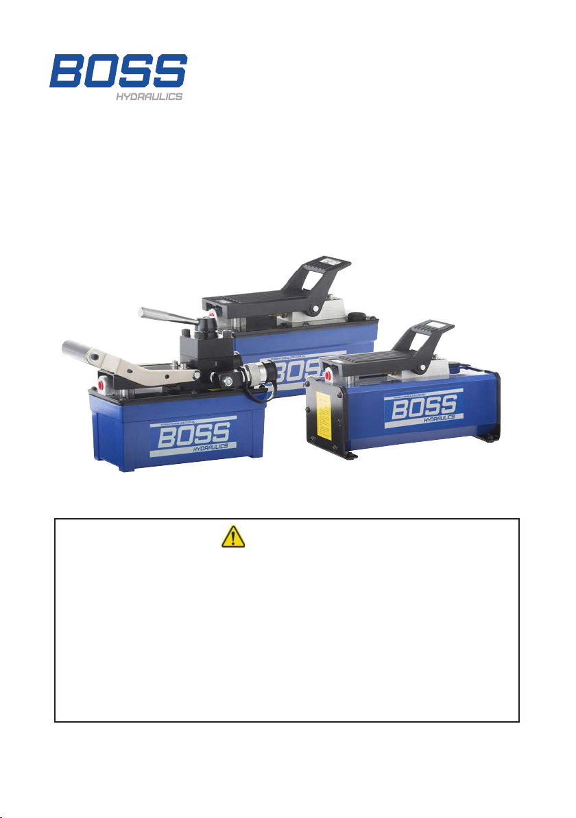
BOSSCO PA010 User manual
Model No.: PA010, PA019, PA019-2, PA019-3, PA019-8, PAD019,
PAD019-3, PAD019-8, PAR019
OPERATING INSTRUCTIONS
Air Pumps- 700 Bar (10,000 psi)
WARNING
Read and follow all Safety Instructions, Warnings, Cautions and
Important information provided in this manual before using the
equipment. They are provided for the safety of those operating the
equipment and to prevent personal injury and/or damage to property
when using this equipment.
THIS EQUIPMENT SHOULD ONLY BE USED BY OPERATORS
WHO HAVE BEEN TRAINED IN THE SAFE USE OF HIGH
PRESSURE HYDRAULIC EQUIPMENT
www.bosshydraulics.com.au
Form: BM004

BM004-V2
2
WARNING:
• Always wear the correct personal
protective equipment when
operating high pressure hydraulic
tools and equipment.
• Always stay clear of loads
supported by hydraulic systems,
the load must be secured
mechanically before work can
commence.
• Always keep your hands and feet
clear of the work activity during
operation to avoid personal injury.
• Never handle pressurised
hydraulic hoses. Escaping oil
under pressure can penetrate
the skin causing serious injury.
Contact a doctor immediately if
oil is injected under the skin.
• Never operate the system above
the maximum rated output
pressure.
• Never connect to the system
components, ttings, couplers,
hoses, valves etc. that are NOT
rated to the full system operating
pressure.
• Never exceed equipment ratings.
Never attempt to lift a load
greater than the capacity of the
cylinder. Overloading causes
equipment to fail and possible
personal injury or damage to
equipment.
• Boss cylinders and pumps
are designed to operate at a
maximum of 700 bar (10,000 psi)
unless specied. Never connect a
cylinder to a pump with a higher
output pressure.
• Never use pumps and cylinders
with disconnected couplers.
Always ensure where couplers
are used that they are all fully
engaged. Failure to do so can
result in the system becoming
overloaded and can result in a
catastrophic component failure
potentially causing severe
personal injury.
• Always ensure the system has
a stable set up before operating
the equipment. Cylinders should
be located on a at surface that
has the capacity to support the
load, cylinder bases and other
supports should be used where
applicable. Avoid situations where
the load is not directly centred on
the cylinders. Loads that are o
centre place considerable strain
on the cylinder and piston. This
can result in the load slipping or
the cylinder failing with potentially
dangerous results. Always
distribute the load evenly across
the entire surface of the cylinder
saddle. Always use a saddle to
protect the cylinder rod.

BM004-V2 3
IMPORTANT:
• Never lift or carry hydraulic
equipment by the hose or
couplers. Use carry handles or
another safe method to transport
or lift components.
• High pressure hydraulic
equipment should only be
serviced, adjusted, repaired and
tested by qualied hydraulic
technicians.
• After unpacking the equipment
it should be inspected by a
qualied person to ensure
there is no shipping damage or
missing part.
• A gauge is highly recommended
to be used, so the pressure in
the hydraulic system can be
monitored.
CAUTION:
• Avoid damage to hydraulic
hoses from sharp objects,
vehicles and heavy objects
falling on them, never kink or
t hoses with a sharp bend in
them. All of these things can
cause internal damage to the
hose leading to premature
hose failure.
• Keep hydraulic equipment
away from sources of
heat and ames. Heat will
soften seals and hoses
which results in hydraulic
uid leaks. For optimum
performance, equipment
should not be exposed to
temperatures of 65° C (150°
F) or higher. Always protect
hoses from weld splatter
or sparks from cutting or
grinding tools.
• Never weld to or modify
cylinders, pumps or other
system components as
they have been engineered
and tested to meet specic
standards.
• Always immediately replace
worn or damaged parts with
genuine Boss Hydraulics
parts. The use of non-
genuine parts can result in
failure potentially causing
personal injury and/or
property damage.
WARNING:

BM004-V2
4
1. INSTALLATION
• The lubrication oil for the air system should be SAE grade oil (5W-30W)
or equivalent and it should be set at 1 drop per minute. The thread
protector for the air inlet can be removed and replaced with an air
connection that is used locally. The air connection should be tightened
rmly 27-34Nm (20-25ft-lbs).
• PA010 and PA019 pumps are single acting and require only 1 hydraulic
hose. PAD019 pumps are double acting will have an external 3 position
valve and will require 2 hydraulic hoses which connect to the “A” and “B”
ports on the valve.
• When connecting hoses,
ttings or couplers to the
threaded ports on the
pump use a thread paste
sealant that remains soft,
it should be applied to
the male thread being
careful not to allow it into
the hydraulic system. If
using thread tape the rst
thread or 2 should be left
completely free of tape
so it does not end up in
the hydraulic system and
cause a failure, 1 or 2
layers of tape is sucient
to provide a seal. Threads
should be tightened rmly
88-100Nm (65-75ft-lbs),
overtightening can split
housings.
• The power source for the
pump is compressed air
therefore it is essential
that a lter regulator and
lubricator (FRL) unit is
tted to the airline before
the pump to remove
Dirt and water from the compressed air and add oil to lubricate the pump
internals

BM004-V2 5
2. COMMISSIONING
• With the pump on a level surface
the shipping plug should be
removed from the ller breather
port on the pump and the oil level
checked. The oil level should be
20mm (3/4”) below the pump lid if
it is low top the level up with Boss
Hydraulic oil .Then t the ller
breather.
• The pump can now be connected
to a cylinder ensuring all
couplings are fully engaged. For
the rst operation the cylinder
should be positioned below the
level of the oil in the pump.
• The airline can now be connected
to the pump.
• For single acting PA010 and
PA019 pumps depress the end
of the foot pedal end marked
“PUMP” the pump will operate
and the cylinder will extent.
To release the pressure in the
system and retract the cylinder,
depress the end of the foot pedal
marked “RELEASE”.
• For double acting PAD019 pumps
which have a 3 position valve the
hose connected to “A” port on the
valve should be connected to the
bottom or cap end of the cylinder.
• The hose connected to “B” port
on the valve is the connected to
the top or rod end on the cylinder.
With the valve handle in position 1
depress the end of the foot pedal
closest to the air inlet and the
cylinder will extend.
3. OPERATION
• Prior to each use the pump,
hoses and any gauges and
accessories should be visually
inspected and any damaged
components replaced.
• The oil level should be checked
regularly and when necessary
toped up with Boss Hydraulic oil.
• Do not attempt to connecting
unretracted cylinders as they can
cause the reservoir to overow.
• The pump output pressure can
be controlled by adjusting the
input air pressure with an air
pressure regulator however a
hydraulic pressure regulator
tted to the pump output is a
better option.
• To retract the cylinder place the
valve handle in position 3 and
depress the foot pedal. Placing
the valve handle in position 2
will block “A” and “B” ports and
depressing the foot pedal will
circulate oil back to the reservoir.
• For both single acting and double
acting pumps they should be
operated through 3 or 4 cycles
initially to remove any air from
the system.

BM004-V2
6
4. TROUBLESHOOTING
PROBLEM CAUSE SOLUTION
Pump will NOT
start Low air supply Check air supply
Pump stalls under
load Low air pressure Check air supply
Pump operates but
cylinder doesn’t
move
Low oil level Check oil level
Coupling not fully
connected Check couplings
Overloaded at
maximum pressure Check system pressure
External leak Check hoses, couplers and
connectors
Internal leak Contact a Boss Hydraulics
Authorised Service Centre
Suction blocked Contact a Boss Hydraulics
Authorised Service Centre
Breather blocked Contact a Boss Hydraulics
Authorised Service Centre
Pump fails to build
full pressure
Low air pressure Check air pressure
External leak Check hoses, couplers and
connectors
Internal leak Contact a Boss Hydraulics
Authorised Service Centre
4. MAINTENANCE
• Clean after use with warm soapy water being careful not to introduce the
water to the oil in the reservoir through the ller breather.
• When not in use pumps should be stored in a cool dry area free from dust.
• The air lter should be cleaned and drained of water frequently both prior
to use and during long periods of use.
• Change oil after 250 hours use or every 2 years, more frequently in dusty
environments.
• Servicing should be carried out by a qualied hydraulic technician.

BM004-V2 7
4. TROUBLESHOOTING (CONTINUED)
PROBLEM CAUSE SOLUTION
Pump
achieves full
pressure but
doesn’t hold
External leak Check hoses, couplers and
connectors
Internal leak Contact a Boss Hydraulics
Authorised Service Centre
Pump
operated
but cylinder
moves slower
than normal
Low air supply/ Dirty air lter Check air supply/ air lter
Poor connection Check hoses, couplers and
connectors
Restriction in the hydraulic line Check hydraulic lines for
blockages or damage
Leak in the system Check for external leaks
Cylinder will
not return
May require a load to retract Check cylinder type
Poor connection Check coupler
Restriction in the hydraulic line Check hydraulic lines for
blockages or damage
Blockage in the pump valve Contact a Boss Hydraulics
Authorised Service Centre
Broken spring in the cylinder Contact a Boss Hydraulics
Authorised Service Centre
5. SPECIFICATIONS
Model Input air pressure
(bar)
Air consumpon
(cfm)
Oil Cap.
(cc)
Useable Oil
(cc)
Weight
(kg)
PA010 7-10 9 850 750 5.4
PA019 7-10 9 1600 1300 7.3
PAR019 7-10 9 1600 1300 8.5
PA019-2 7-10 9 2600 2000 9.1
PA019-3 7-10 9 3000 2500 9.3
PA019-8 7-10 9 8000 7200 14
PAD019* 7-10 9 1600 1300 9.1
PAD019-3* 7-10 9 3000 2500 12
PAD019-8* 7-10 9 8000 7200 17
* Suitable for both Single and Double Acting Cylinders.

BOSS HYDRAULICS:
Head Ofce: 19 Ricketts Road, Mt Waverley VIC 3149 I P: 1300 BOSS HYD (1300 267 749)
E: [email protected] I W: www.bosshydraulics.com.au
This manual suits for next models
8
Table of contents
Other BOSSCO Water Pump manuals


Popular Water Pump manuals by other brands


Danfoss
Danfoss NovoCon L operating guide

Regulus
Regulus CSE2 MIX-BP F W 1F Installation and operation manual

Watson Marlow Pumps
Watson Marlow Pumps 323Dz manual

emaux
emaux SPV Series user manual

Durr Dental
Durr Dental VSA 300 S Installation and operating instructions

Pattfield Ergo Tools
Pattfield Ergo Tools PE-TP 1000 N instructions

Lowara
Lowara e-LNEEE Installation, operation and maintenance manual

Hozelock
Hozelock Flood Pump 7825 manual

Lutz-Jesco
Lutz-Jesco MEMDOS SMART LK operating instructions

Rinnai
Rinnai HJ COOPER LC Series Owner and installer guide

Renkforce
Renkforce 2302377 operating instructions

Zoeller
Zoeller X71 Series owner's manual