manuals.online logo
Brands
  1. Home
  2. •
  3. Brands
  4. •
  5. Boston Acoustics
  6. •
  7. Speakers
  8. •
  9. Boston Acoustics MCenter User manual

Boston Acoustics MCenter User manual

M Series
Loudspeakers
OWNER’S MANUAL / SAFETY INSTRUCTIONS / COMPLIANCE INFORMATION
Español
Parlantes
Serie M
Français
Haut-parleurs
Serie M
2
IMPORTANT SAFETY INSTRUCTIONS
This symbol found on the apparatus indicates hazards
arising from dangerous voltages.
This symbol found on the apparatus indicates the user
should read all safety statements found in the user
manual.
This symbol found on the apparatus indicates double
insulation.
WARNING!
To reduce the risk of fire or electrical
shock, do not expose this apparatus to rain or moisture.
This symbol found on the apparatus indicates that
the apparatus must be placed in a separate collection
facility for electronic waste and not disposed with
household waste.
1. Read these instructions.
2. Keep these instructions.
3. Heed all warnings.
4. Follow all instructions.
5. Do not use this apparatus near water.
6. Clean only with dry cloth.
7. Do not block any ventilation openings. Install in accordance
with the manufacturer’s instructions.
8. Do not install near any heat sources such as radiators, heat
registers, stoves, or other apparatus (including amplifiers)
that produce heat.
9. Do not defeat the safety purpose of the polarized or
grounding type plug. A polarized plug has two blades with
one wider than the other. A grounding-type plug has two
blades and a third grounding prong. The wide blade or
the third prong is provided for your safety. If the provided
plug does not fit into your outlet, consult an electrician for
replacement of the obsolete outlet.
10. Protect the power cord from being walked on or pinched
particularly at plugs, convenience receptacles, and the point
where they exit from the apparatus.
11. Only use attachments/accessories specified by the manu-
facturer.
12. Unplug this apparatus during lightning storms or when
unused for long periods of time.
13. Refer all servicing to qualified service personnel. Servicing
is required when the apparatus has been damaged in any
way, such as power-supply cord or plug is damaged, liquid
has been spilled or objects have fallen into the apparatus,
the apparatus has been exposed to rain or moisture, does
not operate normally, or has been dropped.
14. Maintain a minimum distance of 2” (50mm) around the
front, rear, and sides of the apparatus for sufficient ventila-
tion. The ventilation should not be impeded by covering the
ventilation openings or placing on or around the apparatus
items such as newspapers, table-cloths, curtains, etc.
15. No open flame sources, such as lighted candles, should be
placed on the apparatus.
16. The apparatus shall not be exposed to dripping or splash-
ing. No objects filled with liquids, such as vases, shall be
placed on the apparatus.
17.
Either the power inlet connector on the rear of the apparatus
or the power plug at the wall must remain accessible, to be
able to disconnect power from the apparatus.
18. T
o completely disconnect this apparatus from the AC
Mains, disconnect the power supply cord plug from the
AC receptacle.
19.
The mains plug of the power supply cord shall remain readily
operable.
American Users:
Note: This equipment has been tested and found to comply with
the limits for a Class B digital device, pursuant to part 15 of the
FCC Rules. These limits are designed to provide reasonable
protection against harmful interference in a residential installation
.
This equipment generates, uses, and can radiate radio frequency
energy and, if not installed and used in accordance with the
instructions, may cause harmful interference to radio commu-
nications. However, there is no guarantee that interference will
not occur in a particular installation. If this equipment does cause
harmful interference to radio or television reception, which can
be determined by turning the equipment off and on, the user is
encouraged to try to correct the interference by one or more of
the following measures:
• Reorient or relocate the receiving antenna.
• Increase the separation between the equipment and
receiver.
• Connect the equipment into an outlet on a circuit differ-
ent from that to which the receiver is connected.
• Consult the dealer or an experienced radio/TV technician
for help.
Canadian Users
This class B digital apparatus complies with Canadian ICES-003.
Cet appareil numérique de classe B est conforme á la norme
NMB-003 du Canada.
Use only with the cart, stand, tripod, bracket, or
table specified by the manufacturer, or sold with
the apparatus. When a cart is used, use caution
when moving the cart/apparatus combination
to avoid injury from tip-over.
3
Introduction
Thank you for selecting Boston Acoustics. The M Series family of loudspeakers is designed to deliver exceptionally accurate
and natural sound reproduction from an aesthetically pleasing design. Each M Series model is specifically engineered to
provide superior acoustic results for the intended application.
The M350, M340, M250 and M25 utilize the Extended Wide Bandwidth (EWB) tweeter and Boston Lo-Q™ Cabinet
construction for pure sound reproduction and minimal interference from the cabinet. The MCenter and MSurround utilize
an innovative new Balanced Mode Radiator (BMR) high-frequency driver to provide even sound output over a remarkably
wide area for clear dialog reproduction and an immersive surround-sound field for all listeners. The look of the M Series
includes traditional and modern design cues that provide exceptional sonic results and allow them to easily integrate in a
wide variety of home décors. All of the M Series models are designed to blend seamlessly with each other and to mix and
match with other Boston Acoustics speakers providing great results regardless of the system configuration and speaker
types. We hope that you enjoy your Boston Acoustics purchase for many years to come.
Features
• Second generation Extended Wide Bandwidth (EWB) Tweeter (M350, M340, M250 & M25) to minimize phase shift and
distortion while improving pistonic motion
• Balanced Mode Radiator (BMR) high frequency diver (MCenter & MSurround) to maximize dispersion resulting in improved
dialog intelligibly and surround-sound field immersion for all listeners
• Polypropylene midrange with mass loading (M350 & M340) provides smooth overall response with minimal coloration
in the critical midrange frequencies
• Polypropylene woofers are lightweight and rigid with large motor structures for maximum low frequency output
and heat dissipation
• Boston Lo-Q™ Cabinet Design (All except MSurround & MSubwoofer) to minimize cabinet response and interference
• Leatherette covered baffle (All except MSubwoofer & MSurround in White)
• Rounded cabinet design with premium quality finish
• Solid aluminum stand-offs (M350, M340 & M250)
• 5-way gold-plated precision binding posts
• High quality crossover network filter circuit boards and components
E
N
G
L
I
S
H
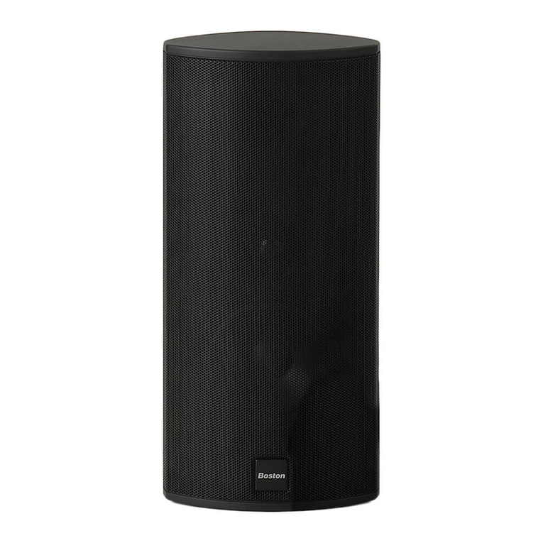
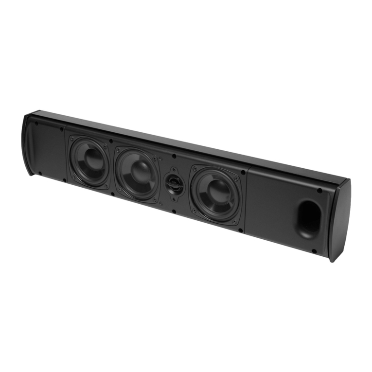
MCenter MSurround
M25
MSubwoofer M250 M340
M350
4
Specifications M350 M340 M250 M25
Frequency Range (±3dB):
45Hz – 30kHz 45Hz – 30kHz 60Hz – 30kHz 62Hz – 30kHz
High-Frequency Driver:
1” (2.5cm) 1” (2.5cm) 1” (2.5cm) 1” (2.5cm)
EWB Dome EWB Dome EWB Dome EWB Dome
Mid-Frequency Driver:
4½” (11.4cm) 4½” (11.4cm) 5¼” (13.3cm) —
mass loaded mass loaded polypropylene cone
polypropylene cone polypropylene cone
mid/low driver
Low-Frequency Driver(s):
4 x 5¼” (13.3cm) 4 x 4½” (11.4cm) 5¼” (13.3cm) 5¼”(13.3cm)
polypropylene cones polypropylene cones polypropylene cone polypropylene cone
Crossover Frequency:
400/3,000Hz 390/3,100Hz 450/2,900Hz 3,000Hz
Impedance:
Compatible with Compatible with Compatible with Compatible with
8 ohm outputs 8 ohm outputs 8 ohm outputs 8 ohm outputs
Sensitivity: [1 watt (2.83V) at 1m]
90dB 88dB 88dB 86dB
Recommended Amplifier Power
50-500 watts 50-350 watts 50-250 watts 50-200 watts
Dimensions (H x W x D):
423/8x 95/8x 123/16” 4 0 3/8 x 813/16 x 117/16” 3 87/16 x 95/8x 913/16” 1 23/8x 615/16 x 103/16”
(107.6 x 24.5 x 31cm) (102.6 x 22.4 x 29cm) (97.6 x 24.5 x 25cm) (31.4 x 17.6 x 25.8cm)
Weight:
55.9 lbs (25.4kg) 46.3 lbs (21.0kg) 35.3 lbs (16.0kg) 14.7 lbs (6.7kg)
Specifications MCenter MSurround
MSubwoofer
Frequency Range (±3dB):
68Hz – 22kHz 95Hz – 22kHz 23Hz – 150Hz
High-Frequency Driver:
2½” (6.4cm) 2½” (6.4cm) —
BMR flat planel BMR flat planel
Low-Frequency Driver(s):
2 x 4½” (11.4cm) 3½” (8.9cm)
10” (25.4cm) polypropylene cone
polypropylene cones polypropylene cone 2 x 8”(20.3cm) polypropylene
cone passive radiators
Crossover Frequency:
700Hz 700Hz 40Hz - 180Hz (variable)
Impedance:
Compatible with Compatible with —
8 ohm outputs 8 ohm outputs
Sensitivity: [1 watt (2.83V) at 1m]
87dB 86dB —
Amplifier Power: — — 500 watts RMS
(1000 watts Peak)
Recommended Amplifier Power
50-200 watts 50-150 watts —
Dimensions (H x W x D):
61/8x 215/8x 71/16” 9½ x 69/16” x 47/16” 1 3 1/16 x 163⁄4x 157⁄16”
(15.5 x 55 x 18cm) (24.2 x 16.6 x 11.3cm) (33.1 x 42.5 x 39.2cm)
Weight:
15.9 lbs (7.2kg) 5.5 lbs (2.5kg) 51.8 lbs (23.5kg)
Specifications subject to change without notice.
5
Unpacking the System
Carefully unpack the speakers. If there is any sign of damage from transit, report it immediately to your dealer or delivery service.
Retain the shipping carton and packing materials for future use.
Grilles
The cloth grilles should remain on the speaker during normal use. However, to remove a grille, use your fingers to carefully
pry the top edge of the grille away from the cabinet so you can insert your fingers between the grille and the cabinet. Then
slide your fingers down the inside of the grille frame from top to bottom which will cause the grille to pop free. The grille is
NOT designed to be removed by only pulling on one side. The pins that hold the grille can be damaged. Also, do not use any
objects other than your fingers to remove the grille as the finish or grille may be damaged. Be careful to keep rings, watches
and other sharp objects from scratching the finish or tearing the grille cloth.
To replace the grille, carefully align the two pins at the top of the grille with their corresponding grommets and gently push
them in until the grille is supported by the grommets. Then work your way down the grille gently pushing the grille pins into
the grommets evenly until the grille is fully seated. Be careful to align the pins with the grommets so the cabinet, grille pins
and grommets are not damaged. Also, take care to support the speaker so it does not tip over or fall off its mounting location
while the grille is being removed or replaced. MCenter Note: The same grille removal and replacement procedures apply
to the MCenter except you will begin at the left or right side and work towards the opposite side. MSubwoofer Note: The
MSubwoofer grille is not removable.
Feet & Spikes
The M350, M340 and M250 come with rubber feet installed at the factory which are ideal for hardwood floors. Spikes are also
included for placement on a carpeted surface. To install the spikes, carefully lay the speaker on its back on a soft, debris-free
surface and remove the rubber feet by hand turning them counter-clockwise. Thread the spikes by hand to make sure they
are inserted properly. Save the rubber feet for future use.
The M25, MCenter, and MSurround come with rubber stand-offs that are designed to be attached to the bottom of the
loudspeaker
when stand, shelf or cabinet mounting. This will minimize the vibration transferred from the loudspeaker to the
stand, shelf or cabinet. It will also help to protect the finish of the loudspeaker and the mounting location. The MSubwoofer
comes with rubber feet installed at the factory.
MSurround Note: It is recommended to mount the rubber stand-offs on the back of the side panels of the MSurround if it is
going to be wall mounted. This will minimize the amount of vibration that is transferred directly to the wall. You may need to
adjust the depth of the mounting screws to help ensure that the speaker is not mounted too loosely or too tightly.
Where to Place the Speakers
6
Front Left and Right Speakers
For optimal results, it is advisable to start with the front left and right speakers positioned 6-12 feet (2-4m) apart from each other,
at least 3 inches (76mm) away from the wall or curtains behind them, and at least 2 feet (0.6m) away from the corners of the room.
Putting the front left and right speakers too close to a wall or corner can produce an unnatural bass reinforcement and side wall
reflections that can detract from the speakers balanced, uncolored sound. If your listening position happens to be less than the
distance the speakers are apart, then you may prefer to aim the front of the speakers’inward toward the primary listening
position (“toe-in”). Experimentation is key to finding the best front left and right speaker positions. Playing a piece of stereo music
that you are very familiar with and has a large range of frequencies is often the simplest way to find the best speaker locations for
your room and listening preferences.
Center Speaker
For optimal results, it is advisable to place the center speaker directly below, behind (perforated screens only) or above the
center of the screen. The BMR driver has extremely wide dispersion characteristics so it is not necessary to “aim” the center
speaker baffle towards the listening position. If placed on a shelf or cabinet, position the speaker so the front of it is flush with
the edge of the shelf or cabinet. This will avoid sound reflections that detract from the balanced, uncolored sound.
Surround Speakers
For optimal results, it is advisable to position the surround speakers directly to the side of the listening position, above ear
level and at least 2 feet (0.6m) away from the corners of the room. If the speakers are mounted more than 3 inches (76mm)
from the ceiling, it is advisable to position the speaker so the two ports are aimed towards the ceiling. If the speaker is
mounted within 3 inches (76mm) of the ceiling, it is advisable to position the speaker so that the two ports are aimed towards
the floor.
There are two 4-way hangers built into the back of the MSurround for wall mounting the loudspeaker vertically or horizontally
with the ports pointing in either direction. It is recommended to mount the rubber stand-offs on the back of the side panels
of the MSurround if it is going to be wall mounted. This will minimize the amount of vibration that is transferred directly to
the wall. Consult a person knowledgeable about your wall type to recommend suitable hardware for hanging the speaker.
Usually it is best to leave soundbar off the wall until connections are made.
Connections
After your speakers are properly placed, you are ready to wire your system.
Loudspeaker Connections
Before you connect the speakers turn off all the system components. The M Series loudspeakers
feature gold-plated 5-way binding posts. They can accept bare wires, pin lugs, spade lugs, banana
plugs or dual banana plugs.
The illustration shows the bare wire speaker connection method. Remove about 3⁄8”(10mm) of
the wire insulation. Twist the strands of the wire into a neat bundle. Loosen the top cap by turn-
ing it counter-clockwise until the hole in the center of the terminal post is fully accessible. Insert
the wire through the hole and turn the top cap clockwise by hand to clamp it in place. Do not
use tools to tighten it. Be sure that no strands of wire are able to make contact with the opposite
terminal post. Repeat for the other loudspeaker connections.
If you are using pin lugs, attach them to the wires as specified by the manufacturer. Loosen the top cap by turning it counter-
clockwise until the hole in the center of the terminal post is fully accessible. Insert the pin lug through the hole and turn the
top cap clockwise by hand to clamp it in place. Do not use tools to tighten it. Repeat for the other loudspeaker connections.
7
If you are using spade lugs, attach them to the wires as specified by the manufacturer. Loosen the top cap by turning it
counter-clockwise until there is enough clearance for the spade lug to be positioned around the terminal post. Place the
spade lug around the post and turn the top cap clockwise by hand to clamp it in place. Do not use tools to tighten it.
Repeat for the other loudspeaker connections.
If you are using single or dual banana plugs, attach them to the wire as specified by the manufacturer. Turn the top cap
of the terminal clockwise to ensure that it is fully seated. Do not use tools to tighten it. Insert the banana plug into the
hole provided in the center of the top cap. Repeat for the other loudspeaker connections.
For information on connecting the speaker wires to your receiver or amplifier, refer to its owner’s manual.
Important!
To ensure the best performance, observe polarities when making loudspeaker connections. The terminal cups have +
and – symbols included on them and the top caps have a red ring for + and black ring for –. Connect each + terminal
on the back of the amplifier or receiver to the respective + (red) terminal on each loudspeaker. Connect the – (black)
terminals in the same way. If the connections are not made correctly, it can cause poor bass response and imaging. Also,
to avoid short circuits that may damage your equipment, be careful not to let the ends of the wires to make contact with
the ends of any other wires.
Subwoofer
For optimal results, place the subwoofer on the same wall (or in a corner) as your front speakers. In principal, the lower
the crossover point, the greater the distance the subwoofer can be from the front speakers, however, the sound is typi-
cally best when the subwoofer is within 12 feet (3.5m) of the front speakers. The perceived level of bass output from the
subwoofer will vary significantly at different positions in the room. When placed near walls, the output level is empha-
sized with corner placement providing the highest perceived output level. Placement away from walls may produce too
little perceived bass.
Regardless of the perceived bass level within the room, you always have the ability to adjust the level
of the subwoofer from the built in volume control or from the level control of your preamplifier or receiver. If at any time
you move the subwoofer, be sure to re-check your outputs levels and EQ settings if any. Since the human ear is less able to
localize low frequencies, the bass will still appear to come from the front speakers. Experimentation is key but most
positions in the room should work well
.
IMPORTANT: Do not place the subwoofer where there is a chance of contact between the rear panel and drapes
or furniture. The amplifier panel also serves to dissipate heat and should have at least 3 inches (76mm) clearance so it
does not overheat.
NOTE: Power is always supplied to the MSubwoofer electronics unless it is unplugged or switched to the OFF position
using the power switch located on the rear panel. The auto-on circuitry only activates or deactivates the power amplifier.
Make sure your MSubwoofer and preamp/receiver are unplugged when making connections.
Power: When plugging in your MSubwoofer be sure to use a wall outlet, or dedicated electrical outlet. Some receivers
will provide a switched outlet. Do not use this. These on board electrical outlets do not offer the amount of current or
proper isolation required by a power amplifier, such as the one in your MSubwoofer.
Line level or LFE:
On most systems use the Line Level input or the LFE input. These inputs accept the line-level signal
from your preamp/receiver’s subwoofer output. Your receiver’s manual should indicate which input is most appropriate.
8
Connecting the Subwoofer to Digital Home Theater Systems Using LFE
Multi-channel home theater electronics dedicate one channel (the “.1”) to reproduce the low-frequency effects (LFE)
(such as explosions and thunder) contained in digitally-encoded soundtracks.
Hooked up this way, the receiver’s amplifier is relieved of having to reproduce the difficult low bass signals that can drive the
receiver into audible distortion. In some cases it can also depend on several other settings within a receiver. We recommend
consulting your receiver manual for further assistance in this area.
Use an audio RCA cable (not included), as shown, to connect your digital receiver’s LFE/subwoofer output to the subwoofer.
Connect the other end to the Line Level/LFE input.
Connecting to Electronics Without a Subwoofer Output
If the preamp/receiver in your system does not have a subwoofer or LFE output you can connect the MSubwoofer
to a preamp/variable output. Use a stereo audio RCA cable (not included) to connect the preamp outputs to the “L” and “R”
Line Level inputs. Note: for preamps without multiple preamp outputs, splitters may be required.
Multi-Channel
AVR or Preamp
Sub Out
9
Adjusting the Crossover Control
When using the Line Level inputs (not the LFE input) the subwoofer’s built-in crossover is engaged. As a starting point, set the
crossover control on the subwoofer about 10Hz higher than the lower limit of your main speakers’ bass response. Fine-tune
the crossover setting by ear for the smoothest blend with your main speakers. The best setting of the crossover control will
depend on speaker placement and personal preference.
Speaker level
Use these high-level terminals with receivers that do not have subwoofer output. The speaker inputs accept both left and right
channel speaker signals from your receiver. When using a home theater receiver, set the speaker type to “Large.” The large
setting will produce a fuller sound.
Note
Certain receivers use speaker grounding circuits that may be incompatible with external powered audio products, such as
powered subwoofers. When speaker wire is used instead of line level cables, this incompatibility can result in an audible hum
when the receiver is turned off or switched to a different speaker channel.
If this should happen with your MSubwoofer,
you will need to make a ground cable and
connect it to either RCA line input on the
subwoofer and any unused RCA line input
or output
on your receiver (see diagram).
The proper
ground cable for this applica-
tion should consist of two male RCA plugs
that have
their negative outside terminals (or
“sleeve”)
connected to each other by any
length of single conductor copper cable.
Note: The inside positive (or "pin") terminals
should not be wired in either plug.
AUDIO
AUDIO VIDEO
VIDEOS VIDEO
V-AUX
IN
VCR
OUT
D-TV
/CBL
DVD
S VIDEO VIDEO
MONITOR OUT
MONITOR
OUT
D-TV
/CBL
DVD
CD
FM
ANT
IN
(PLAY)
MD
/CD-R
OUT
(REC)
75Ω UNBAL.
TUNER
COMPONENT VIDEO
DIGITAL
OUTPUT
DIGITAL
INPUT
6 CH INPUT
CD
COAXIAL
RL
RL
MAIN
SUB
WOOFER
DVD
MD/CD-R
MD/CD-R
OPTICAL
OPTICAL
D-TV/CBL
Y
PB/CB
PR/CR
SURROUND
CENTER
AM
ANT
GND
use either RCA jack
single conductor (-) RCA to (-) RCA ground cable
use any available RCA jack
back of subwoofer
back of receiver
10
MSubwoofer Operation
Audio On/Auto/Mute
Plug the MSubwoofer’s AC cord into a wall outlet. Do not use the outlets on the back of the receiver. Set the Audio On switch
to the desired setting.
AUDIO ON – The MSubwoofer audio is always on.
AUTO – The MSubwoofer audio will turn on whenever a signal is detected. If no signal is detected after several minutes, it will
automatically enter the Mute mode.
MUTE – The MSubwoofer is muted and will not produce any sound. You may want to unplug your MSubwoofer if you will
not be using it for some time or wish to conserve electricity. You may also turn off the main power switch, located next to the
power cord.
An LED indicator next to the Polarity switch indicates what mode the MSubwoofer is in.
OFF – The MSubwoofer is unplugged or power switch is in the "Off" position.
RED – Mute (No signal detected, Audio Off )
BLUE – Audio On (Signal detected, Audio On)
The MSubwoofer will automatically enter the Mute mode after several minutes when no signal is detected from your system.
The MSubwoofer audio will then turn on when a signal is detected.
Polarity Control
(0° or 180°): Selects regular (0°) or inverted (180°) phase for the MSubwoofer. Set this switch to provide the fullest, most
dynamic bass. The effect of phase will be most audible on low-frequency percussion instruments or music with a continu-
ously repeating bass line.
Crossover Control
Adjusts the frequency of the low pass filter for the MSubwoofer. Note: This control is not active when using the LFE input
jack.
Volume Control
Turn the MSubwoofer Volume control to the 11 o’clock position. If no sound emanates from the MSubwoofer check the AC-
line cord, Audio On switch, Power switch, and input cables.
Adjust the MSubwoofer Volume control until you hear a match between the main speaker and MSubwoofer. Bass response
should not overpower the room but rather be adjusted so there is a natural blend across the entire musical range.
Maintenance and Service
All wiring connections should be inspected and cleaned at least once a year.
If a problem does occur, make sure that all connections are properly made, secure and clean. If a problem occurs in one
loudspeaker, rewire that speaker in a different location within the system. Should the problem persist then the problem is
with the speaker. If the speaker works fine in the new position it is a strong indication of an issue with the wiring or
electronics in the system. In the event that your speakers ever need service, contact your Boston Acoustics dealer or visit
bostonacoustics.com.
11
Limited Warranty
Boston Acoustics warrants to the original purchaser of an M Series Loudspeaker that it will be free of defects in materi-
als
and workmanship in its mechanical parts for a period of 5 years from the date of purchase. The warranty period for the
electrical
components of the MSubwoofer is 1 year.
Your responsibilities are to install and use them according to the instructions supplied, to provide safe and secure trans-
portation to an authorized Boston Acoustics service representative, and to present proof of purchase in the form of your
sales slip when requesting service.
Excluded from this warranty is damage that results from abuse, misuse, improper installation, accidents, shipping, or
repairs/modifications by anyone other than an authorized Boston Acoustics service representative.
This warranty is limited to the Boston Acoustics product and does not cover damage to any associated equipment. This
warranty does not cover the cost of removal or reinstallation. This warranty is void if the serial number has been removed
or defaced. This warranty gives you specific legal rights, and you may also have other rights which vary from state to state.
If Service Seems Necessary
First, contact the dealer from whom you purchased the product.
Or contact us via e-mail at:
US: [email protected]
Japan: [email protected]
Asia Pacific: ser[email protected]
If that is not possible, write to:
Boston Acoustics, Inc.
100 Corporate Drive
Mahwah, NJ 07430 U.S.A.
We will promptly advise you of what action to take. If it is necessary to return your subwoofer, please ship it prepaid to
the above address. After it has been repaired, we will return it freight prepaid in the United States and Canada.
For EU Customers Only
This symbol found on the product indicates that the product must not be disposed of with household waste.
Instead, it may be placed in a separate collection facility for electronic waste or returned to a retailer when
purchasing similar product. The producer paid to recycle this product. Doing this contributes to reuse and recycling,
minimizes adverse effects on the environment and human health and avoids any fines for incorrect disposal.
32 7 Constitution Way, Woburn, MA 01801 USA
www.bostonacoustics.com
© 2013.
All rights reserved. Boston, Boston Acoustics, and the B/A ellipse symbol
,
are registered trademarks
and Boston Lo-Q
is a trademark of Boston Acoustics, Inc. Specications are subject to change without notice. 142-004248-5
~Boston-
Please
remove
and
read
the
reverse
side
Retire
y
lea
el
reverse
S'il
vous
plait supprimer et
lire
au
verso
Per
favore di togliere e leggere illata
di
retromarcia
Van
ligen flytta och
las
den motsatta
sidan
Bitte entfernen
Sie
und
lesen
Sie
die
ROckseite
Congratulations
on
you
r purchase
of
a Boston Acoustics M-Series
product.
TheM
-Series utilizes a
high
-
quality
leatherette
as
part
of
its cosmetic
and
acoustic design.Th
is
l
ea
th
er
ette
mater
ial
is
significantly softer
than
wood
and
susceptible
to
develop
ing
temporary
imp
r
ess
ions
wh
ile in
the
packaging.This is
normal
beh
avior
for
this
type
of material and any i
mp
ressions
that
re
main after
unboxing
should
complete
ly
disappear
within
a few
hour
s'
time.
To prevent
the
edge
of
th
e
gr
il
le
from
leaving an
im
p
ress
i
on
in
the
leatherette,
wh
ile in
the
packaging,
it
isshipped
wi
th spacers install
ed
on
th
e g
ri
lle pi
ns.
These spacers
do
not
affect sound
qua
lity
but
should
be
removed
to
allow
the
grille
to
sit fi
at
against
the
cabinet.This will
pr
eve
nt
t
he
grille
from
appearing curved
when
viewed
dir
ectly
from
the
side.To remove the spacer
s,
please refer
to
the
instru
ctio
ns in
th
e
owne
r's manual
for
re
mo
v
in
g and replaci
ng
t
he
g
ri
l
le.
While
the
grille is
re
mov
ed,
the
spacers can
be
easily
remov
ed
from
th
e grille pins
by
h
and
.
Thank you
for
your
support
of
Boston Acoustics.We
ho
pe
that
yo
ur
M-Series
prod
uct
provides
you
w
ith
man
y years
of
enjo
ym
e
nt
!
Felic
i
tac
ion
es
por sucompra de
un
p
rod
ucto
Boston
Acoust
ics
de
Ia
Se
r
ie
M.
Como
partede
su
di
seno
cos
metico
y
acus
t
ico
,
Ia
Se
ri
eM
ha
sido
fa
bricada
encu
erina
de alta
cal
i
dad
r
ec
ubriendoel baffe. La
cu
er
in
a
es
co
nsid
er
ab
le
-
me
nt
e mas
blanda
que
Iamadera
y
ti
ene
tendenciaaadquirir
impresiones
temporal
es
mientras
Ia
unidad
se
encuentra
en
su
embalaj
e.
Este
comportamiento
es
normalen
este
tipodemater
ia
ly
si
riene
ma
r
cas
vis
ib
les
de
sp
ue
sde desembalar
el
producto,
las
mismas
deberfan
desapa
rec
er
completamente
en
unas
cu
a
ntas
horas
.
As
imi
smo,
para
evitar que el borde de
Ia
rej
illamarque Iacuerina mientras
esta
em
bala
da,
se
des
pac
ha
con
es
paciadores
instalad
os
en
la
scla
vijas
de
Ia
parril
la
.
Los
espaciadores
no
afectan
Iacali
dad
del
son
ido y
pue
den
dejar
se
o retirar
se
aelecci6
n.
Si
dese
aquitarlos, par
fa
vor consulte l
as
in
strucci
ones
pa
ra
re
ti
rar
y
reemplaza
r Ia
rejil
la
del
ma
nu
al del
pr
opieta
ri
o.
Esto
ev
i
ta
raque Ia
rejilla
apa
re
zca
curv
ada
cuando
sea
vistadi
re
ctamente
desde
e
llat
er
a
l.
Des
pues
de
re
ti
ra
rIarejilla,
los
espaciadores
se
p
ued
en
extrae
rde
las
cl
av
ij
as
am
ano.
Gr
acias
por
apoya
r
a
Boston
Acoustics.
iEspe
r
amos
qu
e
Ia
Serie
M
le
ofrezca
muchos
anos
de
placer'
Felicitationspour vot
re
ac
hat
d'un produit
Boston
Acoust
i
cs
ser
ie
M.
L
es
ba
ffe
sde Ia
se
r
ie
Msont
reco
uverts
d'un
similicuir
de
haute qua
li
te pourcompleter leur e
st
ht?t
ique.Ce
matt?r
i
au
similicuir
es
t
se
n
sib
lement plus mou que le
bois
et
pl
us
susc
eptiblede
conse
r
ve
rd
es
marques
temp
ora
i
res
l
orsque
l'
apparei
lre
ste
dans
son
emba
lla
ge.
Cest
un comportement normal de
ce
type de m
ateriau
et
si
vous
decouvr
ez
-
des
m
arques
apres
le
debal
lage
,el
les
doivent
dispa
raitrecompletement
en
quel
ques
heu
re
s.
En
outre, pour
ev
iter que lebord de
Ia
gr
il
le
marque
le
si
m
il
icuir dans l
'e
mball
age
,el
le
est
munied'entretoises mont
ees
sur
ses
chev
il
l
es
.
Ces
entretois
es
n'affect
en
t
pas
Ia
qua
li
te
so
nore et peuvent €trecon
se
rv
ees
ou reti
rees
au
choix.
Cec
i evite
a
Ia
grille d'apparaitre courb
ee
vu
ede
profil.
Po
ur
ret
i
rer
l
es
entreto
ises,
co
nsultezl
es
instructions du
man
uel du propri€tairesur Iad
epose
et le
re
montage de
Ia
gri
lle
.U
ne
fo
is
Ia
gr
i
ll
e
est
de
posee,
le
s
en
tr
etoi
se
speuvent
etre
extra
ites
a
Ia
mai
n
de
s
chevi
ll
es
de Ia
gr
ille.
Merci
pourvotre
su
pport
de
Boston
Acoust
i
cs.
Nous
espe
ron
sq
ue
Ia
se
r
ie
M
vo
us
apport
era
de
nombreus
es
an
n
ee
sdep
lai
si
r!
Cong
ratul
azioni perilvostro
acquis
to
di un prodo
tl
o
Bo
ston
Acous
ti
cs
M-
Se
rie
s.
L
aM
-seri
es
e
prodo
tt
acon una
simi
lp
e
ll
ed'
alta
qualitache copre il deflettorecome
pa
rte del suo d
es
ign estetico e
acus
t
ico.
Ques
to
mate
ri
alein
simi
lpe
ll
e
e
cons
iderevolmente piumorbido de
ll
egno e piu
suscett
ibi
le
a
rive
l
are
impro
nt
etempo
ran
ee,
mentre
l'
apparecch
io rimane
ne
l
la
con
fezione
.Qu
es
tacomportamento enormale
pe
rquesta tipo di mate
rial
ee
se
si
presenta
no del
le
impronte visibili dopo l'
ap
e
rtura
de
ll
aconfezi
one,
qu
este
dovrebbero
scompar
i
re
del
tuttoentro
poc
he
or
e.
ln
oltre,
per
evit
are
che
il
bordo
della
g
ri
g
lia
possa
lascia
re
un'impr
on
ta
su
lla
similpe
ll
e,mentre
si
trova
ne
ll
a
co
nfezion
e,
il prod
ot
to viene s
ped
itocon dist
anzia
to
ri
i
nsta
ll
ati
s
ui
perni d
el
lagrigl
ia
.
Ques
ti distanziatori non
influenzano Iaquali
t.3
del suono epo
sso
no
essere
l
asciat
io
ri
moss
i,
se
si
des
ide
ra.
Per
rimu
overe
idist
anz
iatori, si
pregadi
fa
re
ri
ferimento a
il
e
is
truzioni co
nt
enute n
el
manu
ale
di
is
truzio
ni
per
Ia
rimozionee
Ia
sos
tituzione della
g
ri
g
li
a.
Questa impedi
ra
Iagriglia di
appa
ri
re
curva
qua
ndo vistadirettamentadal lato.Ment
re
Ia
gr
igliaviene
r
imossa,
idistanziatori possono e
sse
re
es
t
rat
ti a
mana
dai perni de
lla
grig
li
a.G
ra
zi
e
pe
ril
vo
stro
sup
porto
alia
Boston
Acoustic
s.
Ci
auguriamo
che
Ia
M-
ser
i
es
pos
sa
offrirvi molti
ann
i di divertimento!
Granis
ti
ll
ditt
kop
av
en
Bo
ston
Aco
u
stics
M-
se
ri
eproduk
t.
M-se
rien
ar
ko
nstruerad med
hogkva
litativt kon
st
lader
so
m
tac
ker
me
llan
vaggen
som
en
de
l
av
de
ss
kosme
ti
sk
aoch akusti
ska
des
i
gn.
Detta
k
ons
tladermat
er
ialar
bety
dl
igtmjuk
are
antra
och
mer
6mt~
li
g
t
oc
h
kan
fa
tem
porar
a
av
tr
yc
kda
en
heten
ar
i
forpackn
in
g
en.
Detta
ar
nor
ma
It for
denna
t
yp
av
mate
nal
och
om detfortfarande
finns
nag
ra
sy
nl
i
ga
avt
ry
ck
efter u
ppa
c
knin
gen,
sa
barde
forsvinna
helt efter n
ag
ra timm
ar.
For att forhind
ra
att
kante
n
pa
ga
llr
et
lamnar
avt
rycki
ko
nst
l
adre
t
da
enheten
ar
i
forpac
kningen,
sa
levere
r
as
gal
l
re
t m
ed
mellanrumsbrickori
ns
tallerade
pa
gallrets
st
if
t.
De
ttaforebygger
at
t
ga
ll
re
t
se
rbojt ut nar
man
se
rdet di
rek
t
fra
nsi
da
n.
Des
same
ll
an
l
agg
sbr
i
cko
r
pa
ve
rk
ar
inteljud
kv
a
li
tet
en
oc
h kan
la
mn
as
kva
re
ll
er
av
l
ags
na
s
oms~
onsk
as
.Foratt
av
l
ags
namellanl
aggs
b
ri
c
ko
rn
a,h
anv
isa ti
ll
i
ns
truktion
erna
i a
nv
a
nd
ar
-
handbokenfor hur
man
av
lags
n
ar
me
ll
an
l
aggsb
ri
ckorna
och
sa
tter
pa
ga
ll
ret
ig
en.
Nar
ga
llr
et
ha
r
ta
gitsbort
kan
me
ll
anl
ag
gsbri
c
korna
dr
as
bort
fr~n
gal
l
ret
fo
r
hand.
Tack
for ditt
in
tr
esse
for
Boston
Aco
u
st
i
cs.
Vi
ho
ppas
att
M-
serie
nger d
ig
manga
At
av
noje!
He
r
zl
1ch
en
G
lu
ckw
un
sch
zum Er
wer
b e
in
es
Pr
od
uktsderM-
Ser
ie
von
Bosto
n
Aco
usti
cs
.
Di
eM-
Serie
ist ei
ne
Fam
il
ie
hoc
hw
ertiger
Er
z
eu
gni
sse
mitKu
nst
l
ede
r.Bei
ih
rist jewei
ls
ein Um
le
nkbl
ec
h
in
d
as
opt
isch
eund
akus
ti
sc
heD
es
ign
integriert.
Das
z
ug
ehor
ige
L
ede
ri
mi
tatmate
ri
al ist um eini
ge
s
we
iche
ralsHolz
und
reag
iert emp
fi
ndl
ic
he
r
als
d1
es
es
auf
Kontak
t,
so
das
ssich
sc
hon in derVe
rpa
c
kung
vorObergehe
nd
Dru
ck
stel
l
en
bi
lden k
onne
n.
Di
es
istj
edoch
eine
norma
le
Rea
kt
io
nbei di
ese
rArt
von
Mat
er
ia
l.
Fall
s
Sie
beim
Ent
nehm
en
ausderVerpackung
Unrege
lm
aBigke
itenin
derProduktoptik be
me
rk
e
n:
Diese
verschwind
en
i.
d.
R.
inn
erha
lb w
en
iger Stunden vo
ll
sta
ndig.
Um
zu
sa
tz
li
chzu
ve
rhi
ndern,
dass
d
er
Verpa
c
ku
ngsr
and
wa
hre
nd
des
Verpa
ck
ens
Drucks
te
l
le
n im Kunstl
ede
r
hi
nterl
ass
t,
werden
fOr
denVersand
Abs
t
andh
alter
an
d
en
Sc
hutzgitter
sc
h
ra
ub
en
ang
ebrac
h
t.
Diese
Abstandha
lter
hab
en
ke
in
en
Ei
n
fi
uss
aufdieKlan
gq
ua
li
tat und
ko
n
nen
eingese
tzt blei
be
noder ab
ge
nommen
werden
.
Um
die
Ab
sta
n
dha
lter
abzu
ne
hm
en
,l
esen
Sieim Handbu
ch
nac
h,wie
Sie
das
Sc
hutzgi
tt
er
au
sb
au
en und wiedef ein
se
t
zen
kbnnen.
Dadurc
hwird
da
sGitt
er
vom auftretend
en
gekrummtenw
en
n sied
ir
ekt
v
on
der
Se
iteb
etra
chtet
ve
rhinde
rn
.Wenn
das
Sc
hutzgitt
er
au
sgebaut i
st,
lass
en
sic
hdie
Ab
standh
al
terv
on
Han
d vom
Sc
hutzgitter
he
runterzieh
en
.
Viel
en
Da
nk,
d
ass
S
ie
Bos
ton
Acoustics
lh
rVer
trauen
gesc
henkt
ha
be
n.Wirhoffen,d
ass
Sie
vi
ele
Jahre
la
ng
Fr
e
ud
e
an
lh
ren
Produkt
en
der
M-
Ser
ie
hab
en.

This manual suits for next models

6

Other Boston Acoustics Speakers manuals

Boston Acoustics BRAVO 2 User manual

Boston Acoustics

Boston Acoustics BRAVO 2 User manual

Boston Acoustics VRI595 User manual

Boston Acoustics

Boston Acoustics VRI595 User manual

Boston Acoustics VSi 555W2 User manual

Boston Acoustics

Boston Acoustics VSi 555W2 User manual

Boston Acoustics CS 23 II User manual

Boston Acoustics

Boston Acoustics CS 23 II User manual

Boston Acoustics HSi H460T2 Reference guide

Boston Acoustics

Boston Acoustics HSi H460T2 Reference guide

Boston Acoustics CS225 User manual

Boston Acoustics

Boston Acoustics CS225 User manual

Boston Acoustics Designer Series DX Pro User manual

Boston Acoustics

Boston Acoustics Designer Series DX Pro User manual

Boston Acoustics S65 User manual

Boston Acoustics

Boston Acoustics S65 User manual

Boston Acoustics SE45 User manual

Boston Acoustics

Boston Acoustics SE45 User manual

Boston Acoustics VRi553 User manual

Boston Acoustics

Boston Acoustics VRi553 User manual

Boston Acoustics SE65RC User manual

Boston Acoustics

Boston Acoustics SE65RC User manual

Boston Acoustics HSi 255 User manual

Boston Acoustics

Boston Acoustics HSi 255 User manual

Boston Acoustics CR55 User manual

Boston Acoustics

Boston Acoustics CR55 User manual

Boston Acoustics HSi S6W2 User manual

Boston Acoustics

Boston Acoustics HSi S6W2 User manual

Boston Acoustics Voyager RK5 User manual

Boston Acoustics

Boston Acoustics Voyager RK5 User manual

Boston Acoustics PC520 User manual

Boston Acoustics

Boston Acoustics PC520 User manual

Boston Acoustics VR-MX User manual

Boston Acoustics

Boston Acoustics VR-MX User manual

Boston Acoustics SoundWare XL User manual

Boston Acoustics

Boston Acoustics SoundWare XL User manual

Boston Acoustics S95 User manual

Boston Acoustics

Boston Acoustics S95 User manual

Boston Acoustics Lynnfield VR965 User manual

Boston Acoustics

Boston Acoustics Lynnfield VR965 User manual

Boston Acoustics DSi450 User manual

Boston Acoustics

Boston Acoustics DSi450 User manual

Boston Acoustics SC95 User manual

Boston Acoustics

Boston Acoustics SC95 User manual

Boston Acoustics PW520 User manual

Boston Acoustics

Boston Acoustics PW520 User manual

Boston Acoustics TVee 10 User manual

Boston Acoustics

Boston Acoustics TVee 10 User manual

Popular Speakers manuals by other brands

Philips BM5C/98 user manual

Philips

Philips BM5C/98 user manual

Philips css2133b quick start guide

Philips

Philips css2133b quick start guide

Xoopar Tornado 2 user manual

Xoopar

Xoopar Tornado 2 user manual

Samson MEDIAONE BT3 Product information

Samson

Samson MEDIAONE BT3 Product information

Bang & Olufsen BeoSound 3 Additions and Corrections to the Owner's Manual

Bang & Olufsen

Bang & Olufsen BeoSound 3 Additions and Corrections to the Owner's Manual

Enabling Devices 4090 user guide

Enabling Devices

Enabling Devices 4090 user guide

Panasonic SC-HTB770S quick start guide

Panasonic

Panasonic SC-HTB770S quick start guide

Logitech Mini Boombox Getting started with

Logitech

Logitech Mini Boombox Getting started with

JBL Voyager quick start guide

JBL

JBL Voyager quick start guide

Kenwood KFC-1390ie manual

Kenwood

Kenwood KFC-1390ie manual

Inklang AYERS Two passive user manual

Inklang

Inklang AYERS Two passive user manual

Estelon XB Mk II manual

Estelon

Estelon XB Mk II manual

Boston HSi H460T2 quick guide

Boston

Boston HSi H460T2 quick guide

Bowers & Wilkins Signature 7NT installation manual

Bowers & Wilkins

Bowers & Wilkins Signature 7NT installation manual

Nxg nx-soundbar-40 owner's manual

Nxg

Nxg nx-soundbar-40 owner's manual

KEF LS50 Requirement for firmware update

KEF

KEF LS50 Requirement for firmware update

Miiego AXTIVE MIINI quick start guide

Miiego

Miiego AXTIVE MIINI quick start guide

Soft dB deep quick start guide

Soft dB

Soft dB deep quick start guide

manuals.online logo
manuals.online logoBrands
  • About & Mission
  • Contact us
  • Privacy Policy
  • Terms and Conditions

Copyright 2025 Manuals.Online. All Rights Reserved.