Bouffalo Lab BL602 User manual


Contents
1 System and memory overview ................................ 7
1.1 Introduction ..................................... 7
1.2 Main features .................................... 7
1.3 Function description ................................. 7
1.4 Interrupt source ................................... 9
2 Reset and clock ...................................... 11
2.1 Introduction ..................................... 11
2.2 Reset source ..................................... 11
2.3 Clock source ..................................... 12
3 GLB ............................................ 14
3.1 Introduction ..................................... 14
3.2 GLB function description ............................... 14
3.2.1 Clock .................................... 14
3.2.2 Reset .................................... 14
3.2.3 Bus ..................................... 14
3.2.4 Memory ................................... 15
3.2.5 GPIO overview ............................... 15
3.2.6 GPIO main features ............................. 15
3.2.7 GPIO function description .......................... 15
3.2.8 GPIO function ................................ 16
3.2.9 GPIO output ................................. 18
3.2.10 GPIO input ................................. 19
BL602/604 Reference Manual 2/ 195 @2020 Bouffalo Lab

BL602/604 Reference Manual
3.2.11 GPIO optional function ............................ 19
3.2.12 GPIO interrupt ................................ 19
3.3 Register description ................................. 19
3.3.1 clk_cfg0 ................................... 20
3.3.2 clk_cfg2 ................................... 21
3.3.3 clk_cfg3 ................................... 21
3.3.4 GPADC_32M_SRC_CTRL .......................... 22
3.3.5 GPIO_CFGCTL0 .............................. 23
3.3.6 GPIO_CFGCTL1 .............................. 23
3.3.7 GPIO_CFGCTL2 .............................. 24
3.3.8 GPIO_CFGCTL3 .............................. 25
3.3.9 GPIO_CFGCTL4 .............................. 26
3.3.10 GPIO_CFGCTL5 .............................. 27
3.3.11 GPIO_CFGCTL6 .............................. 28
3.3.12 GPIO_CFGCTL7 .............................. 28
3.3.13 GPIO_CFGCTL8 .............................. 29
3.3.14 GPIO_CFGCTL9 .............................. 30
3.3.15 GPIO_CFGCTL10 .............................. 31
3.3.16 GPIO_CFGCTL11 .............................. 32
3.3.17 GPIO_CFGCTL12 .............................. 33
3.3.18 GPIO_CFGCTL13 .............................. 33
3.3.19 GPIO_CFGCTL14 .............................. 34
4 ADC ............................................ 36
4.1 Introduction ..................................... 36
4.2 ADC main features .................................. 36
4.3 ADC functional description .............................. 37
4.3.1 ADC pins and internal signals ........................ 38
4.3.2 ADC channel ................................ 38
4.3.3 ADC clock .................................. 39
4.3.4 ADC conversion mode ............................ 40
4.3.5 ADC consequence .............................. 40
4.3.6 ADC interrupt ................................ 41
4.3.7 ADC FIFO .................................. 42
BL602/604 Reference Manual 3/ 195 @2020 Bouffalo Lab

BL602/604 Reference Manual
4.3.8 ADC configuration process .......................... 42
4.3.9 VBAT measurement ............................. 43
4.3.10 TSEN measurement ............................. 43
4.4 Register description ................................. 44
4.4.1 gpadc_config ................................ 45
4.4.2 gpadc_dma_rdata .............................. 46
4.4.3 gpadc_reg_cmd ............................... 46
4.4.4 gpadc_reg_config1 ............................. 49
4.4.5 gpadc_reg_config2 ............................. 51
4.4.6 gpadc_reg_scn_pos1 ............................ 52
4.4.7 gpadc_reg_scn_pos2 ............................ 53
4.4.8 gpadc_reg_scn_neg1 ............................ 53
4.4.9 gpadc_reg_scn_neg2 ............................ 54
4.4.10 gpadc_reg_status .............................. 54
4.4.11 gpadc_reg_isr ................................ 55
4.4.12 gpadc_reg_result .............................. 55
4.4.13 gpadc_reg_raw_result ............................ 56
4.4.14 gpadc_reg_define .............................. 56
5 DAC ............................................ 57
5.1 Introduction ..................................... 57
5.2 Main features .................................... 57
5.3 Function description ................................. 57
5.4 Register description ................................. 58
5.4.1 gpdac_config ................................ 58
5.4.2 gpdac_dma_config ............................. 59
5.4.3 gpdac_dma_wdata ............................. 60
6 DMA ............................................ 61
6.1 Introduction ..................................... 61
6.2 DMA main features .................................. 61
6.3 DMA functional description .............................. 62
6.3.1 DMA transactions .............................. 62
6.3.2 DMA channel configuration .......................... 64
6.3.3 Peripheral support .............................. 64
BL602/604 Reference Manual 4/ 195 @2020 Bouffalo Lab

BL602/604 Reference Manual
6.3.4 Linked List Mode .............................. 65
6.3.5 DMA interrupt ................................ 66
6.4 Transmission mode .................................. 66
6.4.1 Memory to memory ............................. 66
6.4.2 Memory to peripheral ............................ 66
6.4.3 Peripheral to memory ............................ 67
6.5 Register description ................................. 67
6.5.1 DMA_IntStatus ............................... 68
6.5.2 DMA_IntTCStatus .............................. 69
6.5.3 DMA_IntTCClear .............................. 69
6.5.4 DMA_IntErrorStatus ............................. 70
6.5.5 DMA_IntErrClr ................................ 70
6.5.6 DMA_RawIntTCStatus ............................ 70
6.5.7 DMA_RawIntErrorStatus ........................... 71
6.5.8 DMA_EnbldChns .............................. 71
6.5.9 DMA_SoftBReq ............................... 71
6.5.10 DMA_SoftSReq ............................... 72
6.5.11 DMA_SoftLBReq .............................. 72
6.5.12 DMA_SoftLSReq .............................. 72
6.5.13 DMA_Config ................................. 73
6.5.14 DMA_Sync ................................. 73
6.5.15 DMA_C0SrcAddr .............................. 73
6.5.16 DMA_C0DstAddr .............................. 74
6.5.17 DMA_C0LLI ................................. 74
6.5.18 DMA_C0Control ............................... 74
6.5.19 DMA_C0Config ............................... 75
6.5.20 DMA_C1SrcAddr .............................. 76
6.5.21 DMA_C1DstAddr .............................. 77
6.5.22 DMA_C1LLI ................................. 77
6.5.23 DMA_C1Control ............................... 77
6.5.24 DMA_C1Config ............................... 78
6.5.25 DMA_C2SrcAddr .............................. 79
6.5.26 DMA_C2DstAddr .............................. 79
BL602/604 Reference Manual 5/ 195 @2020 Bouffalo Lab

BL602/604 Reference Manual
6.5.27 DMA_C2LLI ................................. 80
6.5.28 DMA_C2Control ............................... 80
6.5.29 DMA_C2Config ............................... 81
6.5.30 DMA_C3SrcAddr .............................. 82
6.5.31 DMA_C3DstAddr .............................. 82
6.5.32 DMA_C3LLI ................................. 83
6.5.33 DMA_C3Control ............................... 83
6.5.34 DMA_C3Config ............................... 84
7 L1C ............................................ 86
7.1 Introduction ..................................... 86
7.2 Main features .................................... 87
7.3 Function description ................................. 87
7.3.1 Mutual conversion between TCM and Cache RAM resources ......... 87
7.3.2 Cache .................................... 87
7.4 Register description ................................. 88
7.4.1 l1c_config .................................. 89
7.4.2 hit_cnt_lsb .................................. 89
7.4.3 hit_cnt_msb ................................. 89
7.4.4 miss_cnt .................................. 90
8 IR ............................................. 91
8.1 Introduction ..................................... 91
8.2 IR main features ................................... 91
8.3 Function description ................................. 91
8.3.1 Fixed receiving protocol ........................... 91
8.3.2 Pulse width reception ............................ 93
8.3.3 Normal sending mode ............................ 93
8.3.4 Pulse width transmission ........................... 93
8.3.5 Carrier modulation .............................. 94
8.3.6 IR interrupt ................................. 94
8.4 Register description ................................. 94
8.4.1 irtx_config .................................. 95
8.4.2 irtx_int_sts .................................. 96
8.4.3 irtx_data_word0 ............................... 96
BL602/604 Reference Manual 6/ 195 @2020 Bouffalo Lab

BL602/604 Reference Manual
8.4.4 irtx_data_word1 ............................... 97
8.4.5 irtx_pulse_width ............................... 97
8.4.6 irtx_pw ................................... 98
8.4.7 irtx_swm_pw_0 ............................... 98
8.4.8 irtx_swm_pw_1 ............................... 99
8.4.9 irtx_swm_pw_2 ............................... 99
8.4.10 irtx_swm_pw_3 ............................... 100
8.4.11 irtx_swm_pw_4 ............................... 100
8.4.12 irtx_swm_pw_5 ............................... 100
8.4.13 irtx_swm_pw_6 ............................... 101
8.4.14 irtx_swm_pw_7 ............................... 101
8.4.15 irrx_config .................................. 102
8.4.16 irrx_int_sts ................................. 102
8.4.17 irrx_pw_config ................................ 103
8.4.18 irrx_data_count ............................... 103
8.4.19 irrx_data_word0 ............................... 104
8.4.20 irrx_data_word1 ............................... 104
8.4.21 irrx_swm_fifo_config_0 ............................ 104
8.4.22 irrx_swm_fifo_rdata ............................. 105
9 SPI ............................................. 106
9.1 Introduction ..................................... 106
9.2 Main features .................................... 106
9.3 Function description ................................. 106
9.3.1 Clock control ................................ 106
9.3.2 Master continuous transmission mode .................... 107
9.3.3 Acceptance filtering function ......................... 107
9.3.4 Receive error correction ........................... 108
9.3.5 Slave mode timeout mechanism ....................... 108
9.3.6 I/O transfer mode .............................. 108
9.3.7 DMA transfer mode ............................. 108
9.3.8 SPI interrupt ................................. 109
9.4 Register description ................................. 109
9.4.1 spi_config .................................. 110
BL602/604 Reference Manual 7/ 195 @2020 Bouffalo Lab

BL602/604 Reference Manual
9.4.2 spi_int_sts .................................. 111
9.4.3 spi_bus_busy ................................ 112
9.4.4 spi_prd_0 .................................. 113
9.4.5 spi_prd_1 .................................. 113
9.4.6 spi_rxd_ignr ................................. 113
9.4.7 spi_sto_value ................................ 114
9.4.8 spi_fifo_config_0 ............................... 114
9.4.9 spi_fifo_config_1 ............................... 115
9.4.10 spi_fifo_wdata ................................ 115
9.4.11 spi_fifo_rdata ................................ 116
10 UART ........................................... 117
10.1 Introduction ..................................... 117
10.2 Main features .................................... 117
10.3 Function description ................................. 118
10.3.1 Data format description ........................... 118
10.3.2 Basic architecture diagram .......................... 118
10.3.3 Clock source ................................ 118
10.3.4 Baud rate setting .............................. 119
10.3.5 Transmitter ................................. 120
10.3.6 receiver ................................... 120
10.3.7 Automatic baud rate detection ........................ 121
10.3.8 Hardware flow control ............................ 122
10.3.9 DMA transfer mode ............................. 122
10.3.10 UART interrupt ............................... 122
10.4 Register description ................................. 123
10.4.1 utx_config .................................. 124
10.4.2 urx_config .................................. 125
10.4.3 uart_bit_prd ................................. 125
10.4.4 data_config ................................. 126
10.4.5 utx_ir_position ................................ 126
10.4.6 urx_ir_position ................................ 127
10.4.7 urx_rto_timer ................................ 127
10.4.8 uart_int_sts ................................. 127
BL602/604 Reference Manual 8/ 195 @2020 Bouffalo Lab

BL602/604 Reference Manual
10.4.9 uart_int_mask ................................ 128
10.4.10 uart_int_clear ................................ 129
10.4.11 uart_int_en ................................. 129
10.4.12 uart_status ................................. 130
10.4.13 sts_urx_abr_prd ............................... 130
10.4.14 uart_fifo_config_0 .............................. 130
10.4.15 uart_fifo_config_1 .............................. 131
10.4.16 uart_fifo_wdata ............................... 132
10.4.17 uart_fifo_rdata ................................ 132
11 I2C ............................................. 133
11.1 Introduction ..................................... 133
11.2 Main features .................................... 133
11.3 Function description ................................. 133
11.3.1 Start and stop conditions ........................... 134
11.3.2 Data transmission format ........................... 134
11.3.3 Arbitration .................................. 135
11.4 I2C clock setting ................................... 136
11.5 I2C configuration process ............................... 136
11.5.1 Configuration item .............................. 136
11.5.2 Read and write flags ............................. 137
11.5.3 Slave address ................................ 137
11.5.4 Slave device address ............................ 137
11.5.5 Slave device address length ......................... 137
11.5.6 Data .................................... 137
11.5.7 Data length ................................. 137
11.5.8 Enable signal ................................ 137
11.6 FIFO management .................................. 138
11.7 Using DMA ...................................... 139
11.7.1 DMA transmission process .......................... 139
11.7.2 DMA receiving process ........................... 139
11.8 Interrupt ....................................... 140
11.9 Register description ................................. 140
11.9.1 i2c_config .................................. 141
BL602/604 Reference Manual 9/ 195 @2020 Bouffalo Lab

BL602/604 Reference Manual
11.9.2 i2c_int_sts .................................. 141
11.9.3 i2c_sub_addr ................................ 143
11.9.4 i2c_bus_busy ................................ 143
11.9.5 i2c_prd_start ................................ 144
11.9.6 i2c_prd_stop ................................ 144
11.9.7 i2c_prd_data ................................ 144
11.9.8 i2c_fifo_config_0 ............................... 145
11.9.9 i2c_fifo_config_1 ............................... 146
11.9.10 i2c_fifo_wdata ................................ 146
11.9.11 i2c_fifo_rdata ................................ 146
12 PWM ............................................ 148
12.1 Introduction ..................................... 148
12.2 Main features .................................... 148
12.3 Function description ................................. 148
12.3.1 Clock and divider .............................. 148
12.3.2 Pulse generation principle .......................... 149
12.3.3 PWM interrupt ................................ 150
12.4 Register description ................................. 150
12.4.1 pwm_int_config ............................... 151
12.4.2 pwm0_clkdiv ................................ 152
12.4.3 pwm0_thre1 ................................. 152
12.4.4 pwm0_thre2 ................................. 152
12.4.5 pwm0_period ................................ 153
12.4.6 pwm0_config ................................ 153
12.4.7 pwm0_interrupt ............................... 154
12.4.8 pwm1_clkdiv ................................ 154
12.4.9 pwm1_thre1 ................................. 155
12.4.10 pwm1_thre2 ................................. 155
12.4.11 pwm1_period ................................ 155
12.4.12 pwm1_config ................................ 156
12.4.13 pwm1_interrupt ............................... 156
12.4.14 pwm2_clkdiv ................................ 157
12.4.15 pwm2_thre1 ................................. 157
BL602/604 Reference Manual 10/ 195 @2020 Bouffalo Lab

BL602/604 Reference Manual
12.4.16 pwm2_thre2 ................................. 157
12.4.17 pwm2_period ................................ 158
12.4.18 pwm2_config ................................ 158
12.4.19 pwm2_interrupt ............................... 159
12.4.20 pwm3_clkdiv ................................ 159
12.4.21 pwm3_thre1 ................................. 160
12.4.22 pwm3_thre2 ................................. 160
12.4.23 pwm3_period ................................ 160
12.4.24 pwm3_config ................................ 161
12.4.25 pwm3_interrupt ............................... 161
12.4.26 pwm4_clkdiv ................................ 162
12.4.27 pwm4_thre1 ................................. 162
12.4.28 pwm4_thre2 ................................. 162
12.4.29 pwm4_period ................................ 163
12.4.30 pwm4_config ................................ 163
12.4.31 pwm4_interrupt ............................... 164
13 TIMER ........................................... 165
13.1 Introduction ..................................... 165
13.2 Main features .................................... 166
13.3 Function description ................................. 166
13.3.1 8-bit divider ................................. 166
13.3.2 General timer operating mode ........................ 167
13.3.3 Watchdog timer operating mode ....................... 168
13.3.4 Alarm setting ................................ 168
13.3.5 Watchdog alarm ............................... 168
13.4 Register description ................................. 169
13.4.1 TCCR .................................... 171
13.4.2 TMR2_0 ................................... 171
13.4.3 TMR2_1 ................................... 172
13.4.4 TMR2_2 ................................... 172
13.4.5 TMR3_0 ................................... 172
13.4.6 TMR3_1 ................................... 173
13.4.7 TMR3_2 ................................... 173
BL602/604 Reference Manual 11/ 195 @2020 Bouffalo Lab

BL602/604 Reference Manual
13.4.8 TCR2 .................................... 173
13.4.9 TCR3 .................................... 174
13.4.10 TMSR2 ................................... 174
13.4.11 TMSR3 ................................... 174
13.4.12 TIER2 .................................... 175
13.4.13 TIER3 .................................... 175
13.4.14 TPLVR2 ................................... 176
13.4.15 TPLVR3 ................................... 176
13.4.16 TPLCR2 ................................... 177
13.4.17 TPLCR3 ................................... 177
13.4.18 WMER ................................... 177
13.4.19 WMR .................................... 178
13.4.20 WVR .................................... 178
13.4.21 WSR .................................... 179
13.4.22 TICR2 .................................... 179
13.4.23 TICR3 .................................... 180
13.4.24 WICR .................................... 180
13.4.25 TCER .................................... 180
13.4.26 TCMR .................................... 181
13.4.27 TILR2 .................................... 181
13.4.28 TILR3 .................................... 182
13.4.29 WCR .................................... 183
13.4.30 WFAR .................................... 183
13.4.31 WSAR ................................... 183
13.4.32 TCVWR2 .................................. 184
13.4.33 TCVWR3 .................................. 184
13.4.34 TCVSYN2 .................................. 184
13.4.35 TCVSYN3 .................................. 185
13.4.36 TCDR .................................... 185
14 Revision history ....................................... 186
BL602/604 Reference Manual 12/ 195 @2020 Bouffalo Lab

List of Figures
2.1 Resetsource ................................................. 21
2.2 ClockBlockDiagram............................................. 22
3.1 GPIOBasicStruct .............................................. 25
4.1 ADCblockdiagram.............................................. 46
4.2 ADCClock .................................................. 48
6.1 DMAarchitecture............................................... 72
6.2 LLIarchitecture................................................ 74
7.1 L1carchitecture ............................................... 95
7.2 Cachearchitecture.............................................. 97
8.1 neclogical................................................... 101
8.2 nec....................................................... 101
8.3 rc5logical................................................... 101
8.4 rc5....................................................... 102
9.1 SPIclock ................................................... 116
9.2 SPIignore................................................... 117
10.1UARTdata .................................................. 127
10.2UARTclock.................................................. 128
10.3UARTsample................................................. 129
10.4UARTfixedcharactermode......................................... 130
10.5UARTflowcontrol .............................................. 131
11.1I2Cstop/startcondition ........................................... 143
11.2Mastertransmission ............................................. 144
BL602/604 Reference Manual 13/ 195 @2020 Bouffalo Lab

BL602/604 Reference Manual
11.3Mastertxandslaverx ............................................ 144
11.4Masterrxandslavetx ............................................ 144
11.5TxandRxtogether.............................................. 145
12.1Pwm...................................................... 158
13.1Timerblockdiagram ............................................. 174
13.2Watchdogtimerblockdiagram ....................................... 175
13.3TimerPreload................................................. 176
13.4Watchdogtiming ............................................... 177
13.5Watchdogalarmmechanism ........................................ 178
BL602/604 Reference Manual 14/ 195 @2020 Bouffalo Lab

List of Tables
1.1 Busconnection................................................ 17
1.2 Addressmapping............................................... 17
1.2 Addressmapping............................................... 18
1.3 Interruptdistribution ............................................. 18
1.3 Interruptdistribution ............................................. 19
3.1 Pindescription ................................................ 26
3.1 Pindescription ................................................ 27
4.1 ADCinternalsignals ............................................. 47
4.2 ADCexternalpins .............................................. 47
4.3 Meaning of ADC conversion result . . . . . . . . . . . . . . . . . . . . . . . . . . . . . . . . . . . . . 50
7.1 WayDisablesettings ............................................. 96
11.1Pinlists .................................................... 142
12.1DutyCycleParameters ........................................... 159
14.1Documentrevisionhistory.......................................... 195
BL602/604 Reference Manual 15/ 195 @2020 Bouffalo Lab

1
System and memory overview
1.1 Introduction
The on-chip processor uses RISC-V 32-bit with floating point. With high-speed processing memory system (see
the L1C chapter for details), to achieve high-quality computing efficiency. External to the processor is a multilayer
32-bit AHB architecture with low power consumption, low latency, and high flexibility. The memory section contains
high-speed tightly coupled memory as well as cache and system shared memory. Off-chip memory supports Flash
expansion.
1.2 Main features
• RISC-V 32-bit with floating point
• Multi-layer 32-bit AHB bus architecture
• 96KB high-speed memory
• 180KB system memory
• 128KB read-only memory
• Off-chip memory Flash
1.3 Function description
The BL602 bus connection and address access are summarized as follows: The bus master includes CPU, SDIO,
DMA, encryption engine, and debug interface. The bus includes memory, peripherals, WiFi / BLE. Except the en-
cryption engine can only access the memory, all other bus masters can access all bus slaves.
BL602/604 Reference Manual 16/ 195 @2020 Bouffalo Lab
BL602/604 Reference Manual
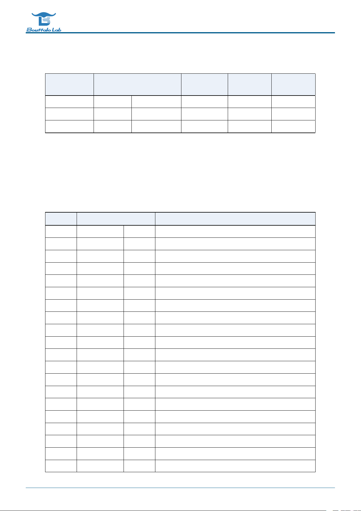
Table 1.1: Bus connection
Slave/Master CPU SDIO DMA encryption
engine
Debug
interface
memory V V V V V
Peripheral V V V - V
WiFi/BLE V V V - V
The address access mainly distinguishes ”memory” or ”peripheral” by [27:24], and the [31:28] bits can be ignored. The
memory space is consecutive addresses 0x2008000 ~ 0x204BFFF (272KB SRAM), the read-only memory address is
0x1000000, and the deep sleep memory address is 0x0010000. The off-chip space address is 0x3000000 (maximum
support 16MB Flash). The peripheral space is 0x0000000 ~ 0x000F000.
Table 1.2: Address mapping
Name Address Size Description
WRAM 0x42030000 112KB Wireless SRAM memory
RETRAM 0x40010000 4KB Deep sleep memory (RAM reserved)
HBN 0x4000F000 4KB Deep Sleep Control (Hibernation)
PDS 0x4000E000 4KB Sleep control (power-down sleep)
SDU 0x4000D000 4KB SDIO control
DMA 0x4000C000 4KB DMA control
QSPI 0x4000B000 4KB Flash control
IRR 0x4000A600 256B Infrared remote control
TIMER 0x4000A500 256B Timer control
PWM 0x4000A400 256B Pulse width modulation control
I2C 0x4000A300 256B I2C control
SPI 0x4000A200 256B SPI master / slave control
UART1 0x4000A100 256B UART control
UART0 0x4000A000 256B UART control
L1C 0x40009000 4KB Cache control
eFuse 0x40007000 4KB eFuse memory control
TZ2 0x40006000 4KB Trust zone isolation
TZ1 0x40005000 4KB Trust zone isolation
SEC 0x40004000 4KB Security engine
GPIP 0x40002000 4KB Universal DAC/ADC/ACOMP interface control
BL602/604 Reference Manual 17/ 195 @2020 Bouffalo Lab

BL602/604 Reference Manual
Table 1.2: Address mapping
Name Address Size Description
MIX 0x40001000 4KB Mixed signal register
GLB 0x40000000 4KB Global register
RAM 0x22020000
/0x42020000
64KB On-chip memory.If used as data memory, use address
0x42020000 for access; if used as program memory, use ad-
dress 0x22020000 for access
XIP 0x23000000 16MB XIP flash
TCM1 0x22014000
/0x42014000
48KB Cache memory.If used as data memory, use address
0x42014000 for access; if used as program memory, use
address 0x22014000 for access
TCM0 0x22008000
/0x42008000
48KB Cache memory.If used as data memory, use address
0x42008000 for access; if used as program memory, use
address 0x22008000 for access
ROM 0x21000000 128KB Read-only memory
1.4 Interrupt source
BL602/BL604 contains a total of 18 interrupt sources. The interrupt sources and corresponding interrupt numbers are
shown in the following table:
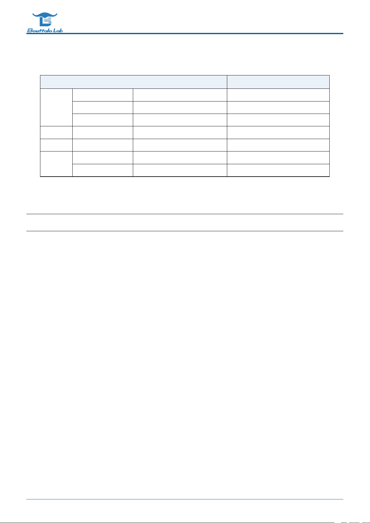
Table 1.3: Interrupt distribution
Interrupt source Number Description
L1C L1C_BMX_ERR IRQ_NUM_BASE+2 L1C BMX Error Interrupt
L1C_BMX_TO IRQ_NUM_BASE+3 L1C BMX Timeout Interrupt
DMA DMA_BMX_ERR IRQ_NUM_BASE+8 DMA BMX Error Interrupt
IR IRTX IRQ_NUM_BASE+19 IR TX Interrupt
IRRX IRQ_NUM_BASE+20 IR RX Interrupt
ADC GPADC_DMA IRQ_NUM_BASE+25 GPADC_DMA Interrupt
SPI SPI IRQ_NUM_BASE+27 SPI Interrupt
UART UART0 IRQ_NUM_BASE+29 UART0 Interrupt
UART1 IRQ_NUM_BASE+30 UART1 Interrupt
I2C I2C IRQ_NUM_BASE+32 I2C Interrupt
PWM PWM IRQ_NUM_BASE+34 PWM Interrupt
BL602/604 Reference Manual 18/ 195 @2020 Bouffalo Lab
BL602/604 Reference Manual
Table 1.3: Interrupt distribution
Interrupt source Number Description
TIMER TIMER_CH0 IRQ_NUM_BASE+36 Timer Channel 0 Interrupt
TIMER_CH1 IRQ_NUM_BASE+37 Timer Channel 1 Interrupt
TIMER_WDT IRQ_NUM_BASE+38 Watch Dog Interrupt
GPIO GPIO_INT0 IRQ_NUM_BASE+44 GPIO Interrupt
PDS PDS_WAKEUP IRQ_NUM_BASE+50 PDS Wakeup Interrupt
HBN HBN_OUT0 IRQ_NUM_BASE+51 Hibernate out 0 Interrupt
HBN_OUT1 IRQ_NUM_BASE+52 Hibernate out 1 Interrupt
Note: The IRQ_NUM_BASE is 16, and the interrupt numbers 0-15 are reserved for RISC-V interrupts.
BL602/604 Reference Manual 19/ 195 @2020 Bouffalo Lab

2
Reset and clock
2.1 Introduction
The reset sources included in the chip: hardware reset, watchdog reset, software reset. The chip contains multiple
clock sources: XTAL, PLL, RC. It is allocated to each module through configuration such as frequency division.
2.2 Reset source
The reset sources are as follows:
• Hardware reset: reset via pins
–Pin global reset (PAD_EXT_RST = 1-> 0): all logic will reset and return to the initial state(for QFN40)
–Pin power reset (CHIP_EN = 0-> 1): similar to power management reset
–Power management reset: The chip is restored from power failure, and the HBN logic resets the chip system
• Watchdog reset
–When the watchdog alarm triggers a reset signal, the reset management unit will reset the chip system after
necessary preparations, and the internal logic of the watchdog will record the status of the watchdog reset
• Software reset: local or partial reset according to software setting register
–Software initial reset (reg_ctrl_pwron_rst): The rising edge of this register is triggered by software to reset the
chip system
–Software CPU reset (reg_ctrl_cpu_reset): The rising edge of this register is triggered by software to reset the
CPU part of the system
–Retain necessary logic processing such as power management unit, perform chip system reset
–Software module reset: Set software reset according to the requirements of specific modules
BL602/604 Reference Manual 20/ 195 @2020 Bouffalo Lab
This manual suits for next models
1
Table of contents
Popular Medical Equipment manuals by other brands


Getinge
Getinge Arjohuntleigh Nimbus 3 Professional Instructions for use

Mettler Electronics
Mettler Electronics Sonicator 730 Maintenance manual

Pressalit Care
Pressalit Care R1100 Mounting instruction

Denas MS
Denas MS DENAS-T operating manual

bort medical
bort medical ActiveColor quick guide

AccuVein
AccuVein AV400 user manual


