BougeRV IU12-2KW User manual

User Manual
12V 2000W High Frequency
Pure Sine Wave Inverter
Limitless energy,limitless life.


Safety Instructions
Feature
Warranty
Appearance and Interface Description
Installation and Wiring
Basic Parameters
Interface Function Description
Protection Function
Common Problems and Solutions
System Maintenance
FAQ
-------------------------------------------- 1
---------------------------------------------------------- 3
-------------------------------------------------------- 4
------------------ 5
-------------------------------------- 6
--------------------------------------------- 9
--------------------------- 11
---------------------------------------- 17
---------------------- 18
-------------------------------------- 21
-------------------------------------------------------------- 22
Content

Safety Instructions
Please follow the safety instructions for operation, the damage caused by not
following the safety instructions shall be borne by the individual.
Please save these instructions
Inverter Safety Information
1. Forbidden for non-professionals to disassemble, repair or modify the inverter.
2. Do not place the inverter where children can touch it.
3. Keep the inverter far away from harsh environments such as damp, greasy, flammable,
explosive, or a large amount of dust.
4. The AC output of the inverter is a high voltage, please do not touch the wiring.
5. Please read the product installation steps to ensure all connections are correct.
6. Do not touch it when it working and keep away from materials or materials affected by high
temperature.
7. Please do not open the terminal protection cover when the inverter is working.
8. Be sure to disconnect the fuse or circuit breaker near the battery and AC output terminals,
before installing and adjusting the wiring of the inverter,
9. After installation, check whether all cable connections are tight to avoid the danger of heat
accumulation due to virtual connections.
10. The inverter is an off-grid, and the input power supply of the load equipment needs to
confirm as the only input device, and do not use in parallel with other input AC power to avoid
damage.
Connection security information
1. The DC voltage must be matched;
Each inverter has a nominal voltage, and the selected battery voltage must be consistent with
the nominal DC input voltage of the inverter. For example, a 12V inverter must select a 12V
battery.
2. The output power of the inverter must be greater than the maximum power of the electrical
appliance;
The maximum power of equipment with large starting energy requirements, such as motors and
air conditioners, cannot be greater than the output power of the inverter, and an additional
power margin is required.
3. The positive and negative poles must be wired correctly;
The diameter of the connecting wire must be thick enough, and the length of the connecting
wire should be minimized.
4. The inverter shell should be properly grounded to avoid personal injury due to leakage.
1

2
Installation Safety Instructions
Before installation, please read this manual carefully and be familiar with the installation
steps.
Be very careful when installing the battery. When installing a lead-acid liquid battery, you
should wear protective glasses. Once you come into contact with the battery acid, please rinse
it with clean water in time.
Avoid placing metal objects near the battery to prevent short circuits of the battery.
Acid gas may be generated when the battery is charged, make sure the surrounding environ-
ment is well-ventilated.
When installing the cabinet, be sure to leave enough space around the inverter for heat
dissipation; do not place the inverter and the lead-acid liquid battery together.
False connection points and corroded wires can cause extreme heat to melt wire insulation,
burn surrounding materials, and even cause fire, so make sure that the connectors are
tightened, and the wires are fixed by cable ties to avoid loose connectors caused by shaking of
the wires during mobile applications.
When installing outdoors, avoid direct sunlight and rainwater infiltration.
After the power switch is turned off, there is still high voltage inside the inverter, please do
not open or touch the internal components, and related operations can only be performed after
the capacitor is fully discharged.
Please do not install the inverter in harsh environments such as damp, greasy, flammable,
explosive, or a large amount of dust.
It is forbidden to reverse the polarity of the battery input terminal of this product, otherwise, it
is easy to damage the equipment or cause unpredictable dangers.
The AC output is a high voltage, please do not touch the wiring.
When the fan is working, do not touch it to avoid injury.
It is necessary to confirm that the inverter is the only input device for the input power of the
load equipment, and it is forbidden to use it in parallel with other input AC power sources to
avoid damage.
Additional Safety note
In order to protect the personal and property safety of users while using this product, the
relevant information is provided in the manual and highlighted with the following symbols.
If you encounter the following symbols in the manual, please read the relevant text carefully.
WARNING: Indicates a hazard of electric shock which, if not avoided, will result in equip-
ment damage or personal electric shock/injury.
ATTENTION: Indicates a potential hazard that, if not avoided, could result in equipment
damage.
NOTE: Indicates an important prompt during operation, failure to execute may cause an
equipment failure alarm.

3
Feature
Reliable
- Advanced SPWM modulation technology pure sine wave output, high power quality.
- High power density and long life components are selected to support long-term
operation at full power.
Efficient
- High conversion efficiency, low loss, low harmonic distortion.
- Three-speed operation mode, ON/OFF/ECO to maximize power saving.
Smart
- Standard Bluetooth, support mobile APP to check device operating parameters.
- With multiple expansion interfaces to meet the diverse needs of users.
Security
- With battery overvoltage, overdischarge protection, output overload, short circuit
protection and over temperature protection (note, no backconnection protection,
please do not backconnect).

4
Warranty
BougeRV provides 1-on-1 Solar Solution. If you have any questions
during use, please feel free to contact us:
If you could provide the following relevant information to our email
(service@bougerv.com)
BougeRV provides an 18-month warranty service for the battery. Please read and follow the
safety instructions in the manual carefully. The warranty service takes effect from the date of
purchase.
Please provide the order number of the purchased product and the serial number (bar code).
Before contacting us: we can provide you with technical support solutions faster.
(1) Voltage of battery
(2) Power of electrical appliance etc.
The company does not assume any responsibility for damages caused by the follow-
ing circumstances
1. Damage caused by improper use or use in an inappropriate place.
2. The current, voltage, and power of the load exceed the limit value of the inverter.
3. Damage caused by the working environment temperature exceeding the limited working
temperature range.
4. Unauthorized disassembly and maintenance of the inverter due to arcing, fire, explosion and
other accidents caused by failure to follow the inverter logo or manual instructions.
5. Force majeure
1-669-232-7427
www.bougerv.com
1-669-232-7427
WhatsApp
5
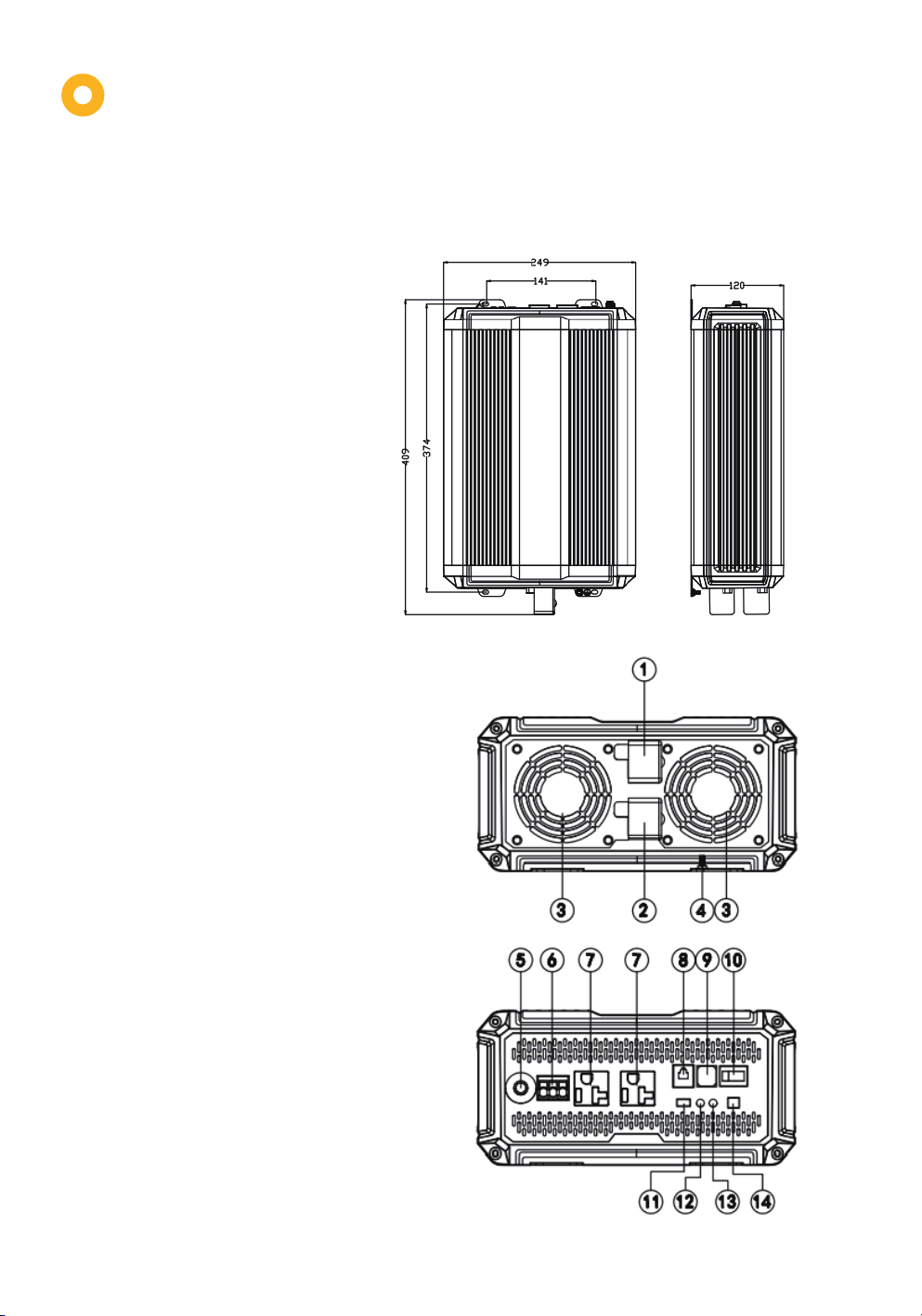
Appearance and
Interface Description
1 Positive electrode of battery input
2 Negative electrode of Battery input
3 Cooling fan
4 Input grounding terminal
5 Output overload protector
6 AC output terminal 1
7 AC output terminal 2
8 RS485 communication interface
9 USB interface
10 ON/OFF/ECO mode switch
11 TTL communication interface
12 Running indicator
13 Fault indicator
14 External switch contact interface
Product size:
409*249*120mm/16.1*9.8*4.7in
Interface Description

6
Installation and Wiring
Installation Steps:
Step 1: Read the user manual carefully.
Step 2: Determine the installation position and heat dissipation space.
Determine the installation position (wall-mounted or horizontal installation mode can be used).
When installing the inverter, ensure that sufficient space is available and the inverter is removed
At least 200mm (7.9in) space should be left between the tuyere and the intake for air circula-
tion.
Step 3: Connect cables
Wiring sequence:
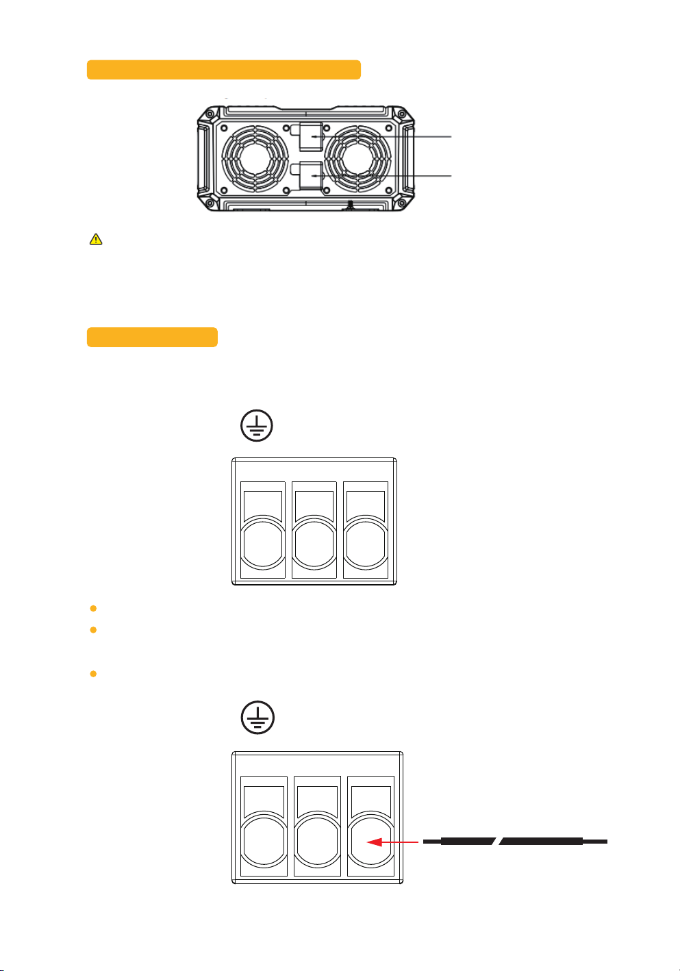
3.1 Ground wire:
If installed in a closed container, ensure that heat dissipation can be dissipated through the
container; otherwise, reduce the amount of heat used.
1. The AC device shall be determined according to the continuous output power of the
inverter, but the impact power of the AC device. Do not exceed the instantaneous impact
power of the inverter. Otherwise, the inverter may be damaged.
2. Before wiring, set the inverter switch to OFF state.
3. During the wiring process, do not close the circuit breaker or safety, and confirm the
lead connection of the electrodes of each component
The connection is correct.
4. The battery end needs to be installed with insurance, which is selected according to
the inverter input rated current of 2-2.5 times
Ensure that the safe position is not more than 150mm away from the battery.
5. The input has no reverse connection protection. Before connecting the battery cable,
ensure that the positive and negative terminals are correctly connected.
Grounding wire
Air inlet
200mm
Air inlet
200mm
200mm 200mm
7
3.2 Battery positive and negative wires
3.3 AC Equipment
1) The device has two AC output interfaces. Connect the load device to the following 3P
terminals if the power of a single load device is higher than 70% of the rated power, defined as
follows:
Single strand copper wire with a wire diameter less than 4 mm² is recommended;
Add soldering tin to the wiring place to make it integral and insert it into the corresponding
hole if multiple strands of wire are used;
Please connect the ground wire first, then the fire wire L and zero wire N.
Input has no reverse connection protection. Before connecting the battery cable, ensure that
the positive and negative terminals are correctly connected; otherwise, the inverter may be
damaged!
N L
N L
BAT+: positive
BAT-: Negative

8
2) The inverter is equipped with 2 standard American standard terminal, as shown in the figure
below, the maximum current bearing capacity of the terminal is 20A.
Step 4: Start the inverter
4.1 Close the circuit breaker at the DC input end of the inverter or the insurance at the battery
end;
4.2 Short-circuit the external switch contact interface of the inverter (factory default short-cir-
cuit state);
4.3 Set the mode switch of the inverter to ON and start the output of the inverter: the running
indicator is steady green and normally outputs AC power;
4.4 Close the circuit breakers on the AC load line, turn on the AC load one by one, and check the
running state of the inverter and the load;
4.5 If the fault indicator is red and the buzzer alarms after the inverter are started, shut down the
load and inverter, please refer to Common problems and solutions for troubleshooting. After the
fault is rectified, repeat the preceding steps.
Stop the inverter to remove the wiring, then use a sharp tool to insert the small hole above the
interface and pull out the connecting wire by force.
N L

9
Basic Parameters
Product Model IU12-2KW Note
Default: 120 V, adjusted by
communication
Rated output power W 2000W
Rated output power vA 2000VA
instantaneous
impact power 4000W
Rated output voltage 110VAC/115VAC/120VAC (±3%)
Default: 60 HZ, adjusted by
communication
OFF mode
Output frequency 50/60 Hz (±0.2%)
Output waveform Pure sine wave
Output harmonic
component THDV<4% (pure resistance load)
Load power factor 0.2-1 (load power ≤ output continu-
ous power)
Rated input voltage 12VDC
The input voltage
ranges 10.8 to 16.0VDC
Rated output
efficiency >89.0%
Maximun output
efficiency >92.0% (30% load)
Standby/ECOcurrent <0.2A
ON mode,no-load
30-100W (adjustable)
No-load current <0.1A
RS485
coumunication
Non-isolated RS485 communication,
power supply5VDC/200mA, interface
set remote switch and CAN commu-
nication function (optional)
USB port Double USB output,5VDC/2A
ON\0FF\ECO Mode
10.8~16.0VDC
ON - AC normal output
OFF - no AC output, standby
ECO - energy-saving mode, auto
switch
Eco startup power <30W
30s-30min (adjustable)
ECO interval time 1 min
TTL interface Non-isolated TTL communication,
power supply 12.5V/200mA
Indicator Green - Operating normally; Red
-Fault

10
Product Model IU12-2KW Note
When this function is used, it
is necessary to switch ON
mode
External switch
contact interfacc
Can be switched on and off by
external relays, mechanical
No input reverse connection
protection!
Protection function
Input over-voltage/over-discharge
protection, output
overload/short-circuit protection,
and device overtemperature
protection
Operating ambient
temperature -20°C - 60°C / -4°F - 140°F
Storage environment
temperature -35°C - 80°C / -31°F - 176°F
Relative humidity ≤95%
Protection level IP20
Heat dissipation
mode
Natural heat dissipation & intelligent
air cooling
Noise ≤60dB
Product size 409*249*120mm/16.1*9.8*4.7in
Installation
dimensions 374*141*φ5mm/14.7*5.6*φ0.2in
The net weight of the
product 6.5kg/14.3lb

11
2 USB interface
Dual USB output interface with a total output capacity of 5V 2A is capable of charging mobile
phone/ PAD and other mobile devices, and no output when the battery is over-discharged or
with over-voltage.
S/N Definition
USB+5.0VDC
NC
NC
USB-
1
2
3
4
Interface Function Description
1 RS485 communication
1) The default baud rate is 9600kps; Check digit: None; Data bit: 8bit; Stop bit: 1bit
2) Interface type RJ45, communication power output specification: 5V/200mA
3) RS485 communication line sequence is defined as follows. The interface integrates remote
switch interface (SW1/SW2) and CAN communication interface
When the port (SW1/SW2) is suspended in open circuit=OFF mode; Switch interface
(SW1/SW2) is short circuited=ON mode.
Switch position Switch position
Positive terminal 5.0 VDC
D+
D-
Power ground
SW1
SW2
CANH
CANL
1
2
3
4
5
6
7
8
3 TTL communication interface
1) The default baud rate is 9600kps; Check digit: None; Data bit: 8bit; Stop bit: 1bit
2) Output specification of communication power supply: 12.5V/200mA
S/N Description
VCC communication power supply output
RX - inverter data receiving end
TX - inverter data sending end
GND - power ground
1
2
3
4

12
4 Operating mode switch
With a 3rd position boat switch, the inverter has 3 operating modes including OFF, ON, and ECO
when the external switch contact is closed.
5 External switch contact interface
2P switch interface: Inverter can work when the interface is short-circuited; Inverter fails to work
when the interface is open. The interface can be connected to a mechanical switch or relay to
control the inverter to start/stop (this application requires keeping the mode switch in the ON or
ECO mode position) in practical application.
Switch position
Remark: When using an APP or other communication devices to switch the working mode,
the current actual working mode will be inconsistent with the boat switch position. The
working mode of the inverter is based on the last adjusted position at the APP or communi-
cation device or the boat switch.
Definition of mode Description of mode
OFF Idle mode, no AC output
Device is in standby idle state, indicator, commu-
nication function, USB output and other functions
are normal, no AC output
ON Normal mode with AC
output Device is in normal working state with AC output
ECO
Application drawing 2: external
relay switch
Relay-SPST
Trigger
signal
Application drawing 1: external
mechanical switch
SW-SPST
Energy-saving mode
with Intermittent AC
output
Device with the detected output load power lower
than the ECO starting power (default 30W) will
automatically close the AC output, enter idle
mode, and re-start the AC output after ECO
interval time (default 1min). And the AC will
continuously output if the load power is larger
than the ECO starting power (+10 W);
13
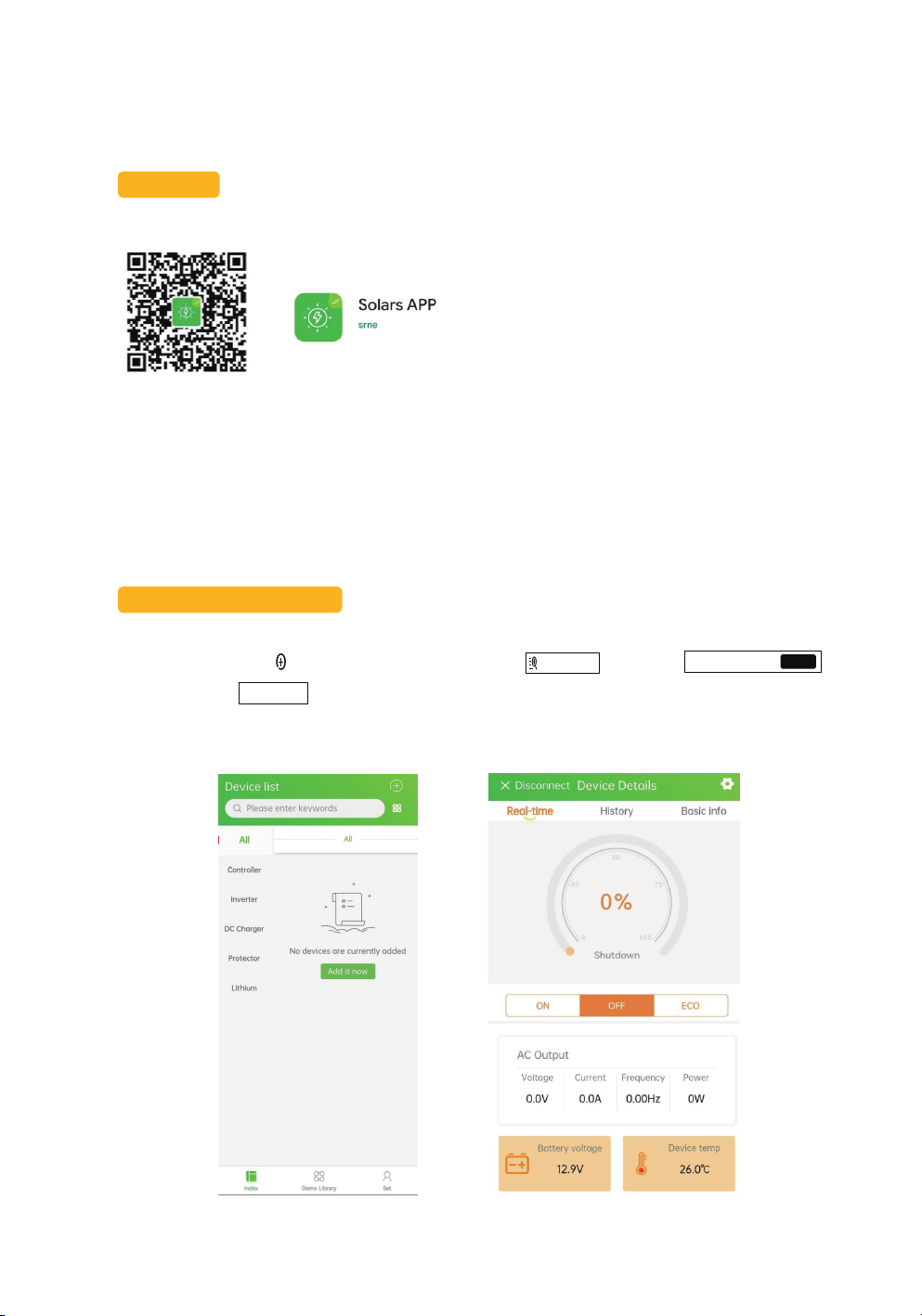
Pairing with You Phone
1. Turn on the Bluetooth and GPS on your phone to enter the ‘Index’ interface 1,
2. After clicking the ‘ ’, search for Bluetooth through ‘ ’ and then
‘ ’
3. Or click the ‘ ’ to connect
4. Enter interface 2 after the connection is successful
Add it now
Add Device BT-TH-300F624D
DC:0D:30:0F:62:4D Connect
6 Bluetooth module
Built-in Bluetooth communication function can monitor the operation data, fault status and
adjust the operation parameters of the inverter in real time through mobile APP.
Download
Scan the QR code on the right to download the application;
IOS & Android
1 2
14
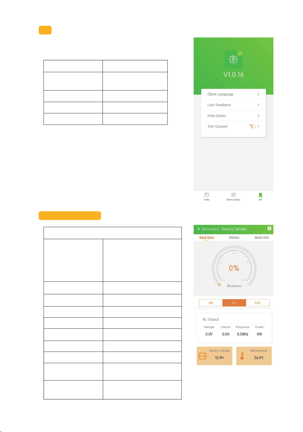
set
Learn about software versions and change settings
Device Information User Setting
1. Client Language Change for English
or Chinese
2. User FeedBack Share Your Advice
3. Help Center Help to Connect
4. Term Convert For °C / °F
APP main interface
Real-time status
1. Percentage
The ratio of inverter output
power to the maximum
power of the inverter. For
example, when the output
power is 500W, the display
value is 25%.
2. ‘ON’State Running Mode
3. ‘OFF’ Idle Mode
4. ‘ECO’ Energy Saving Mode
5. Voltage AC Output Voltage
6. Current Operating Current
7. Frequency AC Frequency
8. Power Output Power
9. Battery Voltag The Battery Voltage Read by
the inverter
10. Equipment
Temp Internal Temp of Inverter
15
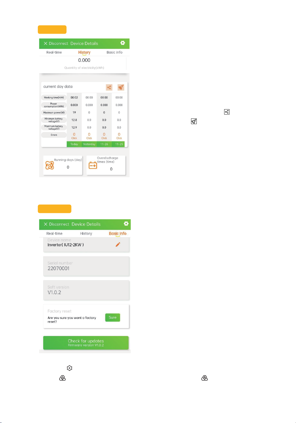
History
The usage data of a week can be viewed and
the accumulated electricity consumption
needs to be counted for 24 hours, and the
electricity consumption of the day is normally
displayed according to the date.
Historical data can be shared in multiple
ways or cleared
Basic info
Know the inverter's serial number 、software
version, and check for updates.
You could also perform factory reset opera-
tions in the interface
Click on it on the main interface to enter the parameter modification interface
Click to save the current parameter settings, and then click here to view the saved data
16
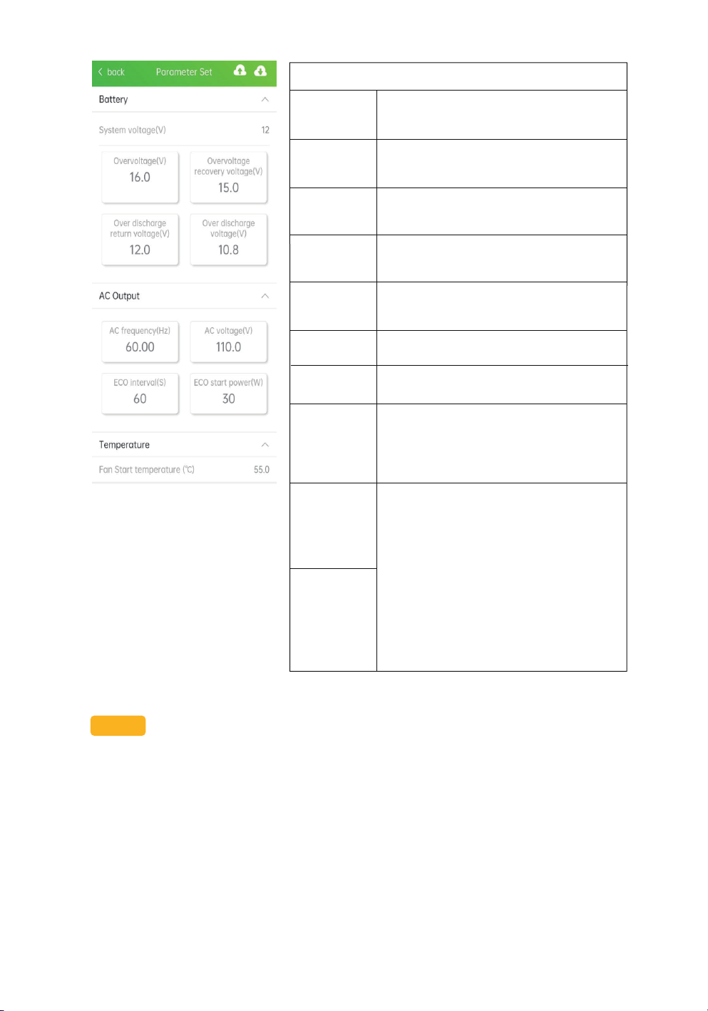
Parameter Set
Voltage of
System
Rate input voltage.
The default value is 12V, which can not
be changed
Overvoltage Battery overvoltage protection voltage
Default 16V, adjustment range is
12-16V
overvoltage
recovery
voltage
Battery overvoltage recovery voltage.
Default 15V,adjustment range is
11-15V
Over-dis-
charge
voltage
Overdischarge protection voltage.De-
fault is 10.8 V, the adjustment range is
10-15V
AC voltage Inverter AC rated output voltage,
default 120V; can be changed to 110V
Frequency Inverter AC rated output frequency,
default 60hz; can be changed to 50HZ
Fan start-up
temp
Inverter internal cooling fan start-up
temp.Can be customized. The
temperature range is 40 ° C-65 ° C OR
104 ° F-149 ° F. Temperature units can
be switched at home
ECO mode
startup
power
ECO interval
time
In energy-saving mode, if the intermittent
AC output is detected with an output load
power less than the set ECO start power
(30W by default) , the AC output is
automatically turned off and put into idle
mode. After the ECO interval (default is 1
minute) , start the AC output again. If the
load power is greater than (ECO start
power + 10W) , AC output start on.
Default interval of 60S with an adjustable
range of 30S-1800S and a default power
of 30W with an adjustable range of
30-100W
Over-dis-
charge return
voltage
overdischarge return
voltage. Default is 15V, the adjustment
range is 11-15.5 V
note:
After turning on the phone's Bluetooth and positioning the connection display connection
timeout, please check the battery voltage, if the battery voltage is lower than the minimum input
voltage, it cannot be connected. If the battery is dormant, please activate the battery and
reconnect it.
17
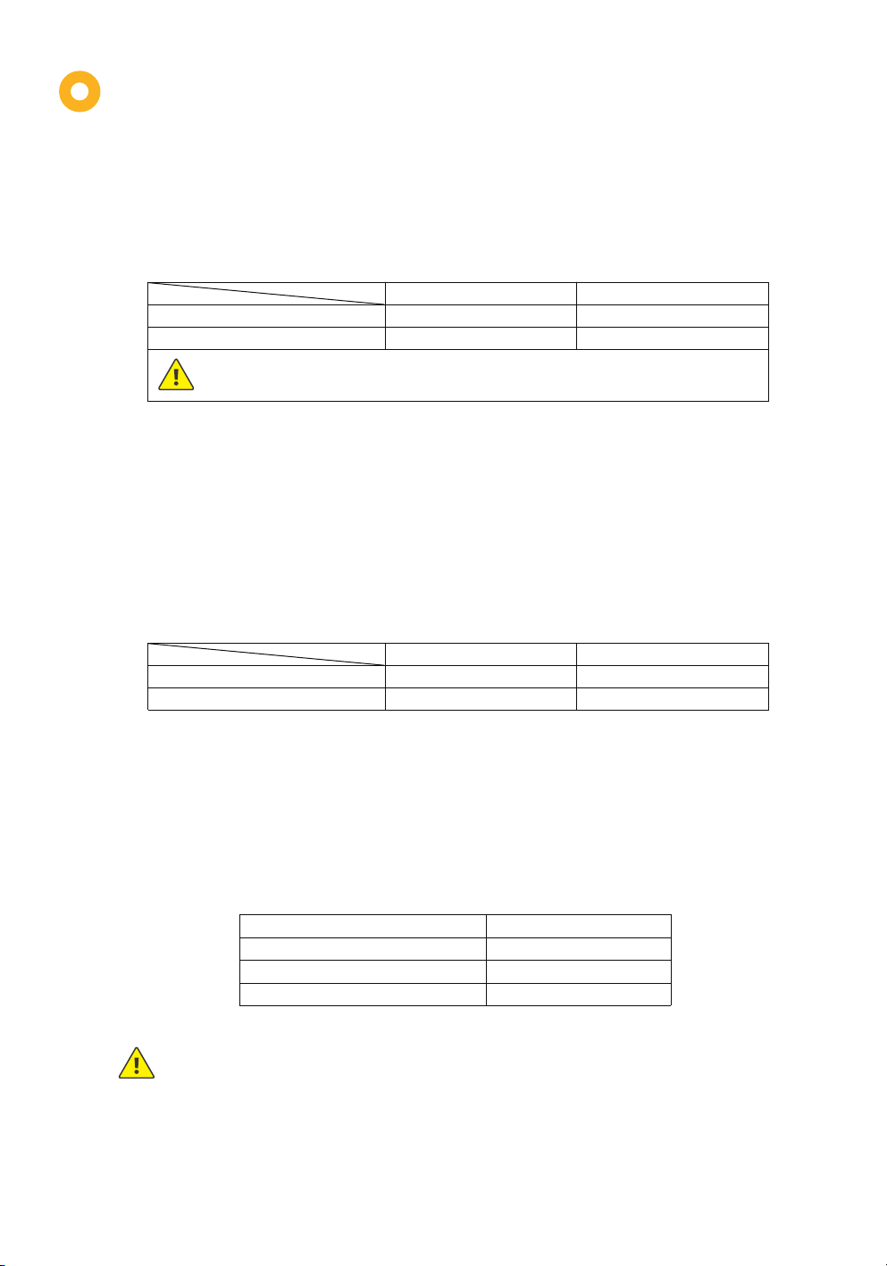
12V system
Input voltage of over-voltage protection 16.0V 32.0V
15.0V 31.0VInput recovery voltage of over-voltage protection
Although the inverter has an input of voltage protection, the input voltage of the 12 V system shall not be higher
than 20 V; The 24 V system input voltage shall not be higher than 35 V, otherwise, the inverter may be damaged.
24V system
Protection Function
1. Input overvoltage protection
When the battery voltage is higher than the input overvoltage protection voltage, the AC output
is turned off, and the fault indicator light and buzzer prompt; when the battery voltage is lower
than the input overvoltage protection voltage -1V, the AC output is restored
3. Output overload protection
When the AC load is greater than the rated output power, corresponding protection is provided
according to different overload levels, as follows:
2. Input low voltage protection
When the battery voltage is lower than the input low-voltage protection voltage, the AC output
will be turned off, and the fault indicator light and buzzer will prompt; when the battery voltage is
greater than
When the low voltage protection recovery voltage is input, the AC output is restored.
!
12V system
Input voltage of over-voltage protection 10.8V 21.6V
12.0V 24.0VInput recovery voltage of low-voltage protection
24V system
!
When the inverter is under overload protection, the AC output has 3 automatic recovery
functions (the first delay is 5s, the second delay is 10s, and the third delay is 15s). It will
not recover automatically for the fourth time. Check the equipment and restart the
inverter after troubleshooting to restore the AC output.
Load power
102% ≤ Po ≤ 120%
120% < Po ≤ 150%
Po﹥150%
Possible duration
1 min
30s
10s
Table of contents
Other BougeRV Inverter manuals

Popular Inverter manuals by other brands


SolarEdge
SolarEdge SE5000H-US installation guide

Fuji Electric
Fuji Electric FRENIC-Lift 400 V Series Starting guide

Redback
Redback SH4600 Guide

Solter
Solter TAPP-1300 instruction manual

Generac Power Systems
Generac Power Systems 4000XL 9777-2 owner's manual

Hitachi
Hitachi SJ700-2 Series instruction manual

SMA
SMA SUNNY TRIPOWER 5.0 SMART ENERGY Quick reference guide

MELINERA
MELINERA 48768 Operation and safety notes

Karl Storz
Karl Storz AUTCON III 400 instruction manual

Darfon
Darfon HB51 Quick installation guide

Zamp Solar
Zamp Solar KIT1009 quick start guide

Riello
Riello CS 25 R Plus Pack of 3 installation instructions