Solter TAPP-1300 User manual

MA UAL DE I STRUCCIO ES
NSTRUCC ONES PARA EL USO Y EL MANTEN M ENTO, LEA ESTE
MANUAL ANTES DE PONER EN MARCHA EL EQU PO
I STRUCTIO MA UAL
NSTRUCT ONS FOR THE USE AND MA NTENANCE, READ TH S
MANUAL BEFORE START NG THE EQU PMENT
MA UAL DE I STRUÇÕES
NSTRUÇÕES PARA O USO E MANUTENÇÃO, LE A ESTE MANUAL
ANTES DE UT L ZAR O EQU PAMENTO
BEDIE U GSA LEITU G
BED ENUNGS- UND WARTUNGSANLE TUNG, LESEN S E D ESE
ANLE TUNG VOR NBETR EBNAHME DES GERÄTES
MA UEL D’I STRUCTIO S
NSTRUCT ONS POUR L’UT L SAT ON ET LA MA NTENANCE, L SEZ
CE MANUEL AVANT DE METTRE L’APPARE L EN MARCHE
ES
M 03000-05 10/2014
INVERTER
E
FR
DE
PT


I TRODUCCIÓ
Agradecemos la deferencia hacia nuestra marca y esperamos le sea de gran utilidad la máquina de
soldar que acaba de adquirir.
El presente manual de instrucciones contiene las informaciones y las advertencias necesarias para
una correcta utilización dentro de las máximas condiciones de seguridad para el operario.
Las máquinas de soldar NVERTER deben ser empleadas por personal experto que conozca y com-
prenda los riesgos involucrados en la utilización de las mismas.
En caso de incomprensión o duda sobre este manual rogamos se ponga en contacto con nosotros. La
manipulación interna del equipo conlleva un peligro importante de descarga eléctrica. Rogamos se
abstenga efectuar cualquier manipulación en el aparato. Sólo personal técnicamente preparado
puede realizarlo.
El fabricante declina toda responsabilidad por prácticas negligentes en la utilización y/o manipulación.
Este manual debe adjuntarse y conservarse con el modelo de máquina adquirido.
Es responsabilidad de las personas que la utilicen y reparen que el producto no deje de cumplir los
requisitos de las normas mencionadas.
SEGURIDAD Y PROTECCIÓ
ELECTRICIDAD
El buen funcionamiento de la máquina se asegura con una buena instalación. Verificar que
la tensión (V) de la máquina corresponde con la de la red.
Debe conectarse S EMPRE la toma de tierra (T).
Personas con elementos eléctricos implantados (MARCAPASOS) no deben utilizar aparatos
de esta índole.
PRE DAS PERSO ALES
Todo el cuerpo del soldador está sometido a la posible acción de agentes agresivos, por lo
que debe protegerse íntegramente. Usar botas de seguridad, guantes, manguitos, polainas
y mandiles de cuero.
PROTECCIÓ CO TRA QUEMADURAS
No tocar nunca con las manos desnudas partes del alambre o el material una vez soldado.
Evitar que las partículas que se desprendan entren en contacto con la piel. No apunte con la
antorcha a ninguna parte del cuerpo.
PROTECCIÓ DE LOS OJOS
Los soldadores y sus ayudantes deben utilizar gafas de seguridad provistas de filtros que
detengan las radiaciones perniciosas para el ojo humano. Usando pantallas especiales es
posible observar la zona de soldadura durante el proceso.
PROTECCIÓ CO TRA I CE DIO
El proceso de soldadura origina proyecciones de metal incandescente que pueden provocar
incendios. No utilizar la máquina en ambientes con gases inflamables. Limpiar el área de
trabajo de todo material combustible. Proteger especialmente las botellas de gas de acuerdo
con los requerimientos que precisen.
PROTECCIÓ CO TRA BOMBO AS DE GAS
Las bombonas que contienen gases de protección los almacenan a altas presiones. Si estas
sufren algún tipo de avería pueden estallar.
Tratar siempre con cuidado las bombonas y soldar lo más lejos posible de ellas.
SOLTER SOLDADURA S.L. I VERTER 1
ES

AL PROCEDER A SOLDAR DEPÓSITOS CO RESTOS DE MATERIALES I FLAMA-
BLES EXISTE U GRA RIESGO DE EXPLOSIÓ . ES RECOME DABLE DISPO ER
DE EXTI TOR LISTO PARA SU USO.
PERTURBACIO ES ELECTROMAG ÉTICAS
Las interferencias electromagnéticas del equipo de soldadura pueden interferir en el funcio-
namiento de aparatos sensibles a esta (ordenadores, robots, etc).
Asegúrese que todos los equipos en el área de soldadura sean resistentes a la radiación
electromagnética.
Para reducir en lo posible la radiación, trabaje con cables de soldadura lo más cortos posi-
bles, y dispuestos en paralelo en el suelo, si es posible.
Trabaje a una distancia de 100 metros o más de equipos sensibles a las perturbaciones.
Asegúrese de tener el equipo de soldadura correctamente puesto a tierra.
Si a pesar de todo hay problemas de interferencias, el operador deberá tomar medidas ex-
tras como mover la máquina de soldar, usar filtros, cables blindados para asegurar la no in-
terferencia con otros equipos.
RECICLADO
En cumplimiento de la normativa Europea 2002/96/EC sobre los desechos de equipos eléc-
tricos y electrónicos. El equipo, al final de su vida útil, debe depositado en su centro de reci-
clado local.
DESCRIPCIO ES GE ERALES
El equipo de soldar con tecnología NVERTER se compone de un circuito electrónico en el que se in-
sertan todos los componentes. El aparato funciona a una frecuencia de unos 70 KHz lo que permite
un cebado del arco óptimo así como una gran homogeneidad en el proceso.
DATOS TÉC ICOS
EC 974 Norma sobre la cual está construido el aparato.
EN 60974 Norma internacional de construcción del aparato.
S/N…. Número de serie.
MMA Soldadura por electrodos revestidos.
T G Soldadura procedimiento T G.
UO Tensión secundaria en vacío.
X Factor de servicio %.
Corriente de soldadura (A).
U Tensión secundaria con corriente de soldadura 2.
U1 Tensión nominal de alimentación.
50/60 Hz Alimentación monofásica 50Hz-60Hz.
Corriente absorbida a la correspondiente corriente de soldadura 2. Cuando
se utiliza el proceso T G dividir por 1.6.
P21 Grado de protección exterior de la máquina.
sApta para trabajar en lugares con riesgo aumentado.
CO EXIÓ A LA RED
Conectar la máquina de soldar en un enchufe provisto de toma de tierra, y se encenderá el piloto
verde. Atención a que la corriente esté dentro de los márgenes (230 V ± 10).
Fuera de estas tensiones la máquina no funcionará. Es obligatorio que la toma de corriente disponga
de la conexión de tierra.
ESQUEMA DEL PA EL FRO TAL
Para la soldadura MMA conectar la pinza de masa en (-)4y la pinza de soldar (+)5si no especifica lo
contrario el fabricante de los electrodos (Fig. 1).
Para la soldadura T G es a la inversa: (+)5pinza masa y el (-)4para la antorcha T G.
1 - Mando potenciómetro para la regulación de la máquina.
2 - LED verde cuando la máquina está en funcionamiento.
SOLTER SOLDADURA S.L. I VERTER 2

3 - LED ámbar cuando existe la intervención térmica o fallo en el suministro eléctrico.
4 - Toma dinse negativa.
5 - Toma dinse positiva.
6 - T G – MMA.
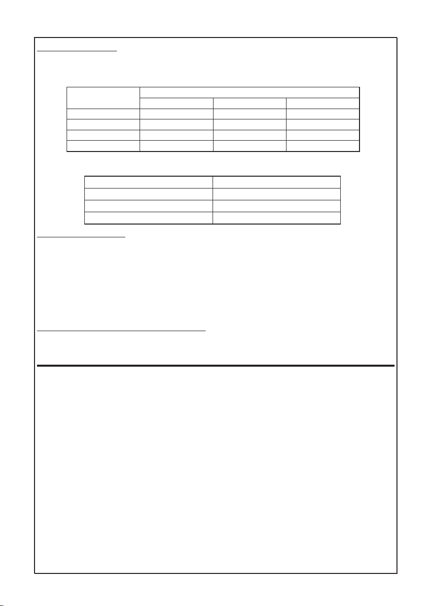
CABLES DE ALARGO
En caso de tener que usar un cable de alargo para conectar la máquina, proceda de acuerdo con la
siguiente tabla:
En caso de querer alargar el cable de masa o el cable de la pinza de soldar:
DISPOSITIVOS DE PROTECCIÓ
PROTECCIÓ TÉRMICA
En el supuesto de un uso prolongado a máxima potencia, al alcanzar unos valores máximos de tem-
peratura la máquina se parará y se encenderá el piloto ámbar. El ventilador seguirá funcionando para
refrigerar la máquina y en pocos minutos ésta volverá a funcionar.
TE SIÓ DE RED I ADECUADA
La máquina se para automáticamente si la tensión de red (V) no es la adecuada.
Se encendería el LED nº 3 ámbar.
Comprobar siempre que ésta se encuentra dentro de los parámetros establecidos.
Particularidad del modelo STYL PRO:
El led ámbar parpadeará si se ha producido un fallo de tensión momentáneo. El fallo puede ser por
exceso o defecto de tensión.
PROCEDIMIE TO DE SOLDADURA MEDIA TE ELECTRODOS REVESTIDOS
• La soldadura por arco eléctrico con electrodos revestidos es un procedimiento por medio del cual se
realiza la unión entre dos partes metálicas aprovechando el calor generado por un arco eléctrico que
se produce entre el electrodo fusible y el material a soldar.
• Las máquinas de soldar pueden ser de corriente continua o corriente alterna; los primeros pueden
soldar cualquier tipo de electrodo, mientras que los segundos pueden soldar solamente electrodos
previstos para corriente alterna.
• La característica constructiva de estas máquinas es tal como para garantizar un buen grado de esta-
bilidad del arco en cuanto a las variaciones de su longitud debidas al acercamiento o alejamiento del
electrodo provocadas por la mano del soldador.
• El electrodo está constituido por dos partes fundamentales:
a) El alma, que es de la misma naturaleza del material de base (aluminio, hierro, cobre, acero,
inoxidable) y cumple con la función de aportar material en la junta.
b) El revestimiento, constituido por varias substancias minerales y orgánicas mezcladas entre si
cuyas funciones son:
Protección gaseosa. Una parte del revestimiento, volatilizada a temperatura del arco, aleja el
aire de la zona creando una columna de gas ionizado que protege el material fundido.
AMP. Alargos de
10m 25m 50m
80-100 A 2,5 mm2 2,5 mm2 4 mm2
130-150-140-160 A 2,5 mm2 4 mm2 4 mm2
160-180 A 2,5 mm2 4 mm2 6 mm2
180-200 A 4 mm2 6 mm2 6 mm2
Hasta 5 m Cable de sección de 16 mm2
De 5 a 20 m Cable de sección de 25 mm2
De 20 a 30 m Cable de sección de 35 mm2
DATOS APROX MADOS.
SOLTER SOLDADURA S.L. I VERTER 3
ES

SOLTER SOLDADURA S.L. I VERTER 4
Aporte de elementos aglutinantes y escorificantes. Una parte del revestimiento se funde y
aporta en el baño de fusión algunos elementos que se combinan con el material del alma.
Los principales tipos de revestimiento son:
Revestimientos al rutilo. Estos revestimientos confieren al cordón una muy buena apariencia
estética por lo cual su empleo está ampliamente difundido. Se puede soldar tanto en corriente
alterna como en corriente continua con ambas polaridades.
Revestimientos básicos. Se utilizan esencialmente para las soldaduras de buena calidad me-
cánica, aunque el arco tiende a salpicar y la estética del cordón resulta inferior a la del revesti-
miento al rutilo. Se utilizan generalmente en corriente continua con el electrodo al polo
positivo (polaridad inversa), si bien existen unos electrodos básicos para corriente alterna. Los
revestimientos básicos son sensibles a la humedad, por tanto deben guardarse en ambiente
seco, dentro de cajas bien cerradas. Recordamos además que los aceros con contenido de
carbono superior a 0,6 es necesario soldarlos con electrodos especiales.
Revestimientos ácidos. Estos revestimientos dan lugar a una buena soldabilidad y pueden
emplearse en corriente alterna o en corriente continua con pinza-porta electrodo al polo nega-
tivo (polaridad directa). El baño de fusión es muy fluido por esa razón los electrodos son aptos
esencialmente para la soldadura en plano.
ELECCIÓ DEL ELECTRODO
La elección del diámetro del electrodo depende del espesor del material, del tipo de junta y de la posi-
ción de la soldadura. Cuando se ejecutan soldaduras “en positivo” el baño tiende a bajar por la fuerza
de la gravedad, por tanto se aconseja utilizar electrodo de pequeño diámetro en pasadas sucesivas.
Para electrodos de diámetro grueso se necesitan elevadas corrientes de soldadura que aporten una
adecuada energía térmica.
ELECCIÓ DE LA CORRIE TE DE SOLDADURA
La estabilidad y continuidad de la soldadura permiten trabajar con corrientes de valores bajos y en
condiciones de particular dificultad.
La tabla siguiente anota indicativamente la corriente mínima y máxima utilizable para la soldadura
sobre acero al carbono.
ESQUEMA DE SOLDADURA CO ELECTRODO REVESTIDO (Fig. 2)
1 - Conectar el cable-masa a la toma negativa de la máquina de soldar (-).
2 - Conectar el cable porta-electrodos a la toma positiva (+).
3 - nsertar el electrodo en la pinza porta-electrodos.
4 - Conectar la máquina a la red.
5 - Situar el potenciómetro nº 2 en una posición adecuada para iniciar la soldadura.
PROCEDIMIE TO DE SOLDADURA TIG
Gas Tungsten Arc Welding (GTAW) es la definición del procedimiento de soldadura en el que el arco,
durante el trabajo, se mantiene por medio de un electrodo metálico infusible (comúnmente tungsteno).
La zona de arco (electrodo y baño de fusión) es protegida contra la contaminación atmosférica por
medio de un gas inerte como argón o helio que fluye continuamente a través de apropiados conduc-
tos en conexión con la antorcha. Por simplificación y uniformidad toda referencia al procedimiento en
este manual es expresada con el térmico T G (Tungsten nert Gas).
DIÁMETRO ELECTRODO CORRIE TE DE SOLDADURA
mm Mínima Máxima
1,6 25 A 50 A
2 40 A 70 A
2,5 60 A 110 A
3,25 100 A 140 A
4 140 A 180 A
5 180 A 200 A

SOLTER SOLDADURA S.L. I VERTER 5
Este procedimiento puede ser usado para efectuar soldaduras limpias y exactas sobre toda clase de
metales respetando su composición físico-química. Gracias a esta característica, la soldadura T G re-
presenta el único método apto para unir ciertos metales.
A causa de estas características inherentes al proceso T G, el planteamiento de la soldadura debe sa-
tisfacer unas especificaciones bien precisas. Los soldadores T G son diseñados y construidos con
estas disposiciones. Al ser instalados, usados y mantenidos en modo correcto ellos pueden proporcio-
nar un largo y satisfactorio servicio creando soldaduras correctas y limpias.
La antorcha T G se conecta directamente con la salida de la máquina de soldar y está inducido en la
antorcha el control manual de gas. El cebado queda facilitado gracias a las características del genera-
dor.
Frecuentemente el cebado del arco se obtiene por medio de un dispositivo llamado de alta frecuencia
(HF) que genera impulsos de alta tensión (kV), en cambio la salida por rozamiento no prevé “alta fre-
cuencia” sino una situación momentánea de corto circuito; en el momento en que se levanta el elec-
trodo se establece el arco y la corriente se transfiere al valor precedente planteado.
ESQUEMA DE SOLDADURA TIG (Fig. 3)
1 - Respetar las indicaciones dadas anteriormente acerca de la primaria y de la instalación.
2 - Conectar el cable masa a la toma positiva + de la máquina de soldar.
3 - Conectar la antorcha a la toma negativa – de la máquina de soldar.
4 - Conectar la bombona de gas (argón) al dispositivo en la antorcha T G.
4 - Proceder a la soldadura regulando la intensidad mediante el potenciómetro.
GAS DE PROTECCIÓ SOLDADURA TIG
El gas de protección normalmente usado es el argón puro con una cantidad variable según la co-
rriente empleada (4-8 l/min).
El procedimiento T G es indicado para la soldadura de los aceros (tanto el carbono como aleados),
permite una soldadura de óptimo aspecto, a menudo es utilizada para la primera pasada sobre tubos.
Es necesario antes de cada soldadura efectuar una esmerada preparación y limpieza de los bordes.
ELECCIÓ DE ELECTRODOS PARA SOLDADURA TIG
Los electrodos normalmente utilizados son de tungsteno con Torio (coloración roja). A título orientativo
damos una tabla con los diámetros y las correspondientes intensidades.
PREPARACIÓ DE ELECTRODOS PARA SOLDADURA TIG
Es necesaria una particular atención en la preparación de la punta del electrodo, según indicamos en
el siguiente dibujo.
El ángulo a varia con la corriente de soldadura; la tabla siguiente aconseja el valor del mismo:
Electrodo (mm) Corriente de soldadura (A)
1,6 5-35
2 30-100
2,4 100-160
Ángulo ()Corriente de soldadura (A)
30 5-30
60-90 30-120
90-120 120-160
ES

SOLTER SOLDADURA S.L. I VERTER 6
MODELOS DIGITALES
DESCRIPCIÓ
1 - Selector.
2 - ndicador de anomalías.
3 - Corriente de refuerzo del arco (Ifor): Modo MMA. Este parámetro configura el incremento de la co-
rriente de pico durante la soldadura para incrementar la potencia de soldadura al acortar el arco. Los valores
de ajuste son del 0% al 25% de incremento sobre 1.
4 - Corriente de soldeo (I1): En este parámetro introduciremos la corriente en amperios que el equipo debe
suministrar, esta dependerá del electrodo utilizado. El límite de ajuste está comprendido entre 10A y 200A
(según modelo).
5 - Corriente de Inicio (Ihot): Modo MMA. Determina la corriente de inicio de arco (Hot Start), mejorando la
arrancada de electrodos difíciles. En este caso los valores posibles son desde el 0% al 25% de incremento
sobre 1. Una vez seleccionado el % de incremento, se podrá seleccionar el tiempo durante el que se apli-
cará la corriente Ihot.
6 - ndicador de unidad en amperios (A).
7 - ndicador de unidad en segundos (S).
8 - ndicador de unidad en porcentaje (%).
9 - Display.
10 - ndicador de modo para electrodos revestidos (MMA).
11 - ndicador de modo para electrodos de tungsteno (TIG).
SELECCIO AR TIPO DE SOLDADURA
Pulsar 1 durante 2 segundos. En la pantalla aparece _ _ _. Girar 1 para seleccionar entre el modo MMA i el
T G. Pulsar nuevamente 1 para confirmar la selección.
MODIFICAR U PARÁMETRO
Girando a derecha o izquierda el selector 1, podemos seleccionar el parámetro deseado. El número de pará-
metros disponible dependerá del tipo de soldadura seleccionado. Pulsar brevemente 1 para poder modificar
el parámetro, el LED indicador parpadeará. Girar el selector 1 para conseguir el valor deseado. Pulsar nue-
vamente 1 para confirmar la modificación. Algunos parámetros pueden ser dobles, como por ejemplo hot.
En este caso con el mismo LED iluminado nos indicará dos valores, % de la corriente i el tiempo en segun-
dos.
PARÁMETROS E MODO MMA
- I1 (A): Corriente principal de soldadura
- Ihot (%): Corriente de nicio.
- Thot (S): Tiempo de aplicación de Ihot
- Ifor (%): Corriente de refuerzo del arco
PARAMETROS E MODO TIG
- I1 (A): Corriente principal de soldadura
LED A OMALÍA
Este se iluminará siempre que exista una anomalía en el equipo, puede ser por tensión inferior al límite o por
sobrecalentamiento. Es normal que la anomalía se encienda en los primeros segundos del arranque del
equipo. En la pantalla aparece Er1.
I
1
I
for.
I
hot.
A
%
S
1
2
345
6
7
8
9 10 11

SOLTER SOLDADURA S.L. I VERTER 7
POSIBLES A OMALÍAS Y SOLUCIO ES
POSIBLES A OMALÍAS Y SOLUCIO ES E LA MÁQUI A
A OMALÍAS E EL PROCESO DE SOLDADURA
FIGURAS
MODELO TAPP, COTT (Fig. 1)
MODELO COTT S, STYL (Fig. 2)
MODELO COTT SD, STYL Di. (Fig.3)
POLARIDAD MMA / TIG (Fig. 4 / 5)
ESQUEMA ELÉCTRICO (Fig.6)
DESPIECES
GAMA TAPP (Fig. 7)
1- Circuito nverter TAPP; 2- nterruptor; 3- Ventilador; 4- Circuito de regulación
GAMA COTT (Fig. 8)
1- Circuito nverter COTT; 2- nterruptor; 3- Ventilador; 4- Circuito de regulación
GAMA COTT S (Fig. 9)
1- Circuito nverter COTT S; 2- nterruptor; 3- Ventilador; 4- Circuito de regulación
GAMA STYL (Fig. 10)
1- Circuito nverter STYL / STYL Di; 2- nterruptor; 3- Ventilador; 4- Circuito de regulación
GAMMA STYL PRO (Fig.11)
1- Circuito nverter STYL PRO; 2- Conmutador; 3- Ventilador; 4- Circuito de regulación
A OMALÍA POSIBLE CAUSA
No se pone en marcha LED verde
apagado (Fig. 2).
Verificar si hay tensión en la toma de corriente.
nterruptor defectuoso.
Apagar el equipo o desconectarlo durante 1 minuto, volver
a intentar la puesta en marcha.
Circuito electrónico defectuoso.
La regulación de soldadura no es
correcta.
Potenciómetro de regulación defectuoso.
Verificar posición potenciómetro.
La máquina no funciona y tiene el
LED ámbar encendido (Fig. 3).
Máquina sobrecalentada y en fase de enfriamiento, espe-
rar a que se recupere.
La tensión no es la adecuada.
Uso de un alargo no apropiado
Error 1 (modelos digitales).
Máquina sobrecalentada y en fase de enfriamiento, espe-
rar a que se recupere.
La tensión no es la adecuada.
Uso de un alargo no apropiado
A OMALÍA POSIBLE CAUSA
Poca penetración
Baja intensidad de soldadura.
Velocidad excesiva al soldar.
Polaridad invertida.
Poros en la soldadura Electrodo húmedo.
Pieza muy fría al soldarla.
Salpicaduras Exceso de intensidad de soldadura.
Arco inestable Pieza con óxido, o mal preparada para soldar, revisar el
contacto de la pinza de masa.
ES

ESPECIFICACIO ES TÉC ICAS
MODELO TAPP-1300 TAPP-1500 COTT-1500 COTT-135 COTT-145 COTT-155
Voltaje de entrada (V) 230 ± 10% 230 ± 10% 230 ± 10% 230 ± 10% 230 ± 10% 230 ± 10%
Frecuencia (Hz) 50 – 60 Hz 50 – 60 Hz 50 – 60 Hz 50 – 60 Hz 50 – 60 Hz 50 – 60 Hz
Voltaje circuito abierto Vcc (V) 80 95 60 75 75 75
Ciclo de trabajo del 100% (A) 30 20 65 55 60 65
Ciclo de trabajo del 60% (A) 45 40 95 75 80 90
Ciclo de trabajo del 35% (A) 80 (25%) 90 (25%) 130 (25%) 110 130 150
ntensidad de alimentación (A) 19 14 26 20 26 28
Potencia absorbida (KVA) 2,2 33,3 44,5 5,5
Índice de protección P23 P23 P23 P23 P23 P23
Dimensiones (mm) 110x190x245 110x190x245 120x230x255 120x230x255 120x230x255 120x230x255
Peso (Kg) 1,9 1,9 3,5 3,5 3,5 3,5
Ø máx. de los electrodos (mm) 2,5 2,5 3,25 3,25 3,25 4
MODELO COTT-1800 S COTT-175 SD COTT-195 SD STYL-185 Di. STYL-185 STYL-1900 STYL-205 Di.
Voltaje de entrada (V) 230 ± 10% 230 ± 10% 230 ± 10% 230 ± 10% 230 ± 10% 230 ± 10% 230 ± 10%
Frecuencia (Hz) 50 – 60 Hz 50 – 60 Hz 50 – 60 Hz 50 – 60 Hz 50 – 60 Hz 50 – 60 Hz 50 – 60 Hz
Voltaje circuito abierto Vcc (V) 95 95 95 80 80 80 80
Ciclo de trabajo del 100% (A) 80 85 90 90 90 130 140
Ciclo de trabajo del 60% (A) 105 90 120 140 140 180 200
Ciclo de trabajo del 45% (A) 155 (25%) 160 (30%) 180 160 160
ntensidad de alimentación (A) 27,5 29 35 29 29 28 38
Potencia absorbida (KVA) 6,3 6,5 86,5 6,5 6,2 9
Índice de protección P23 P23 P23 P21 P21 P21 P21
Dimensiones (mm) 133X280X300 133X280X300 133X280X300 305x115x225 305x115x225 305x115x225 305x115x225
Peso (Kg) 3,9 3,9 4447,5 7,5
Ø máx. de los electrodos (mm) 4 4 4 4 4 4 4
SOLTER SOLDADURA S.L. I VERTER 8

SOLTER SOLDADURA S.L. I VERTER 9
ES

I TRODUCTIO
Thank you for choosing our brand, we hope that the welding machine you have purchased will serve
you well.
This instruction manual contains the necessary information and warnings for correct use within the
maximum operator safety conditions.
NVERTER welding equipment must be used by expert personnel who know and understand the risks
involved in the use of this equipment.
f you have any doubts or queries concerning this manual please contact us. nternal manipulation of
the equipment involves the risk of electric shocks. We request you not to carry out any manipulation of
the equipment. Only technically trained personnel can do this.
Solter Soldadura denies all responsibility for negligent practices in the use or manipulation of this ma-
chine.
This manual must be kept with the equipment purchased.
t is the responsibility of those persons who use and repair this machine to comply with the require-
ments of the above mentioned regulations.
SAFETY A D PROTECTIO
ELECTRICITY
The correct operation of the machine can be ensured through its correct installation. Verify
that the electric current (V) of the equipment corresponds to that of the electricity supply.
ALWAYS connect the earth terminal (T).
Those persons carrying electronic body implant devices (PACEMAKERS) must not use
equipment of this type.
PERSO AL CLOTHI G
The entire body of the welder is subject to possible contact with aggressive agents and so
must be totally protected. Use safety boots, gloves, oversleeves, gaiters and leather aprons.
BUR PROTECTIO
Never touch parts of the wire or the material with your bare hands once soldered. Avoid skin
contact with airborne particles. Do not point the torch at any part of the body.
EYE PROTECTIO
Welders and their assistants must use safety masks or goggles with filters which stop harm-
ful radiation entering the eyes. Use special and screens if possible to observe the welding
area during the process.
FIRE PROTECCIÓ
The welding process produces flying incandescent metal parts which may cause fires. Do
not use the machine in areas where there may be inflammable gases. Clean the working
area of all inflammable material. Pay special attention to the protection of the gas cylinders in
accordance with the necessary requirements.
PROTECTIO FOR GAS CYLI DERS
Cylinders containing gas (fire extinguishers etc.) store their contents at high pressure. f
these suffer any form of damage they may explode. Always treat these cylinders with care
and weld as far away from them as possible
WELD NG N TANKS WH CH MAY CONTA N THE TRACES OF NFLAMMABLE MATER -
ALS NS DE NVOLVES A H GH R SK OF EXPLOS ON. WE RECOMMEND KEEP NG AN
EXT NGU SHER READ LY AVA LABLE FOR USE.
SOLTER SOLDADURA S.L. I VERTER 1

ELECTROMAG ETIC DISTURBA CES
Electromagnetic interferences produced by welding equipment may interfere in the operation
of equipment which is sensitive to this kind of interference (computers, robots etc).
Ensure that all the equipment in the welding area is resistant to electromagnetic radiation.
n order to reduce radiation as much as possible work with welding wires as short as possi-
ble, placed in parallel on the floor if possible.
Work at a distance of 100 metres or more from equipment which is sensitive to disturbances.
Ensure that the machine equipment is correctly earthed.
f there are interference problems despite having taken the above described precautionary
measures, the operator must take extra measures such as moving the welding machine, and
the use of filters or protected cables to ensure that interference with other equipment does
not occur.
RECYCLI G
n compliance with European Directive 2002/96/EC on waste electric and electronic equip-
ment this equipment must be deposited in your local recycling centre at the end of its useful
life.
GE ERAL DESCRIPTIO S
Welding equipment which uses NVERTER technology comprises an electric circuit in which all the
components are inserted. The equipment functions at a frequency of 70 KHz which permits an opti-
mum arc starting as well as a constant weld.
TECH ICAL DATA
EC 974 This equipment has been constructed in keeping with this regulation.
EN 60974 nternational regulation for the construction of this equipment.
S/N…. Serial number.
MMA Welding using coated electrodes
T G T G welding process.
UO Secondary electric voltage in vacuum.
X Service factor %.
Welding current (A).
U Secondary current with a welding current of 2.
U1 Nominal supply current.
50/60 Hz 50Hz-60Hz single phase supply
Current absorbed into the corresponding welding current of 2.
When the T G process is used divide by 1.6.
P21 Equipment external protection grade.
S Apt for work in high-risk locations.
MAI S SUPPLY CO ECTIO
Connect the welding machine into a plug socket with an earth connection and the green pilot light will
come on. Ensure that the current is within the margins of (230 V ± 10).The machine will not operate
outside of these limits. The connection to the mains supply MUST have an earth terminal.
FRO T PA EL DIAGRAM
For MMA welding connect the earth clamp (-)4 and the welding clamp (+)5 if not otherwise specified
by the manufacturer of the electrodes.
For T G welding the process is the other way around: (+)5 for the earth clamp and (-)4 for the T G
torch.
1 - Potentiometer control for machine regulation.
2 - Green LED when the machine is operational.
3 - Amber LED when thermal intervention occurs or the electric supply fails.
4 - Negative dinse socket.
5 - Positive dinse socket.
6 - T G – MMA.
SOLTER SOLDADURA S.L. I VERTER 2
E
EXTE SIO CABLES
Where an extension cable has to be used to connect the machine, proceed in accordance with the fol-
lowing
Where the earth cable or the clamp cable for welding is to be extended:
PROTECTIO DEVICES
THERMAL PROTECTIO
During prolonged use at maximum power, the equipment will stop on reaching maximum temperature
values and the amber pilot light will come on. The fan will continue to function in order to cool the ma-
chine, and in a few minutes the equipment will start again.
I ADEQUATE ELECTRICAL POWER
The machine will stop automatically if the electrical power (V) is inadequate.
The amber LED nº 3 will light up.
Always check that the electrical supply is within the established limits.
Special Characteristics of the STYL PRO model:
The amber LED will flash if the power supply has been cut off momentarily. This may be due to an ex-
cess or deficit of power.
WELDI G PROCEDURE USI G COATED ELECTRODES
• Electric arc welding using coated electrodes is a procedure through which a joint is made between
two metallic parts, making use of the heat generated by an electric arc which is produced between the
melting electrode and the material to be soldered.
• Welding equipment may be DC or AC; the former can weld any type of electrode while the latter can
only weld electrodes made for AC.
• The manufacturing characteristics of these machines guarantee a high degree of arc stability with re-
spect to length variations from the electrode caused by the welder’s hand.
• The electrode is made up of two basic parts:
a) The core which is the same type of base material (aluminium, iron, copper, steel, stainless
steel) and provides material to make the join.
b) The coating, which is made of various mineral and organic substances mixed together and
with the functions of:
Gas protection. One part of the coating is activated at arc temperature and moves air away
from the area, creating a column of ionised gas which protects the melted material.
Provision of agglutinating and dross materials: A part of the coating melts and provides ele-
ments which combine with the core material in the fusion process.
The main types of coating are:
Stick welding coatings. These coatings lend the seam a better appearance and they are
widely used. Welding may be carried out using both AC and DC currents with both polarities.
Basic coatings. These are used essentially for high quality mechanical welding, although the
AMP. Extensions of
10m 25m 50m
80-100 A 2,5 mm2 2,5 mm2 4 mm2
130-150-140-160 A 2,5 mm2 4 mm2 4 mm2
160-180 A 2,5 mm2 4 mm2 6 mm2
180-200 A 4 mm2 6 mm2 6 mm2
Up to 5 m Cable section of 16 mm2
Up 5 to 20 m Cable section of 25 mm2
Up 20 to 30 m Cable section of 35 mm2
TH S DATA S APPROX MATE
SOLTER SOLDADURA S.L. I VERTER 3

arc tends to spatter and the appearance of the seam is less attractive than that of coated stick
welding. DC current is generally used with the electrode at the positive connection (reverse
polarity), although there are some basic electrodes for AC currents. The basic coatings are
sensitive to humidity and therefore should be stored in a dry place inside sealed boxes. You
are reminded that steels with carbon content of over 0.6 must be welded with special elec-
trodes.
Acid coatings. These coatings provide high degree welding and can be used with AC or DC
with a clamp-electrode on at the negative terminal (direct polarity). The molten pool is highly
liquid and so the electrodes are basically suited to flat welding.
THE CHOICE OF ELECTRODE
The choice of the diameter of the electrode depends on the thickness of the material, on the type of
joint, and on the position of the weld. When “positive” welds are made the pool tends to lower due to
gravity, and therefore use of a small diameter electrode is recommended for repeated welds. Large di-
ameter electrodes need high welding currents which provide adequate thermal energy.
CHOICE OF WELDI G CURRE T
The stability and continuity of the weld mean that work can be carried out with low value currents in
difficult conditions.
The following table shows the minimum and maximum current which can be used for carbon steel
welding.
ELECTRODE DIAMETER WELDI G CURRE T
The stability and continuity of the weld mean that work can be carried out whith low value currents in
difficult conditions.
The following table shows the minimum and the maximum current which can be used for carbon steel
welding.
WELDI G SCHEME WITH COATED ELECTRODE(Fig. 2)
1 - Connect the earth cable to the negative terminal on the welding machine (-).
2 - Connect the electrode-carrier cable to the positive terminal (+).
3 - nsert the electrode into the electrode-carrier clamp.
4 - Connect the machine to the electrical supply.
5 - Place potentiometer nº 2 in a suitable position in order to begin welding.
TIG WELDI G PROCEDURE
Gas Tungsten Arc Welding (GTAW) is the name of the welding procedure in which the arc is main-
tained during work through an infusible metallic electrode (usually tungsten)). The area of the arc
(electrode and molten pool) is protected against atmospheric contamination through the use of an inert
gas such as argon or helium which flows continually through the appropriate conducts in connection
with the torch. For purposes of simplification and uniformity all references to this procedure in this
manual use the term T G (Tungsten nert Gas).
This procedure may be used in clean and precise welds on all types of metal, respecting their physi-
cal-chemical composition. Due to this characteristic, T G welding is the only apt method for joining cer-
tain metals.
ELECTRODE D AMETER WELD NG CURRENT
mm Minimum Maximum
1,6 25 A 50 A
2 40 A 70 A
2,5 60 A 110 A
3,25 100 A 140 A
4 140 A 180 A
5 180 A 200 A
SOLTER SOLDADURA S.L. I VERTER 4
E

Due to these inherent characteristics in the T G welding process the welding process to be carried out
must satisfy certain exact specifications. T G welders are designed and constructed in accordance
with these specifications. Correct installation, use and maintenance will result in a long, satisfactory
service, providing clean and proper welding.
The T G torch is connected directly to the outlet of the welding machine and the manual gas control is
induced in the torch. Starting is facilitated by the characteristics of the generator.
The starting of the arc is often obtained through the use of a high frequency (HF) device which gener-
ates high voltage impulses (kV), however “high frequency” is not anticipated in scratch ignition but a
momentary short-circuit situation; at the moment that the electrode is raised, the arc is produced and
the current is transferred to the previously established value.
TIG WELDI G SCHEME (Fig.3)
1 - Respect the previously detailed indications on preparation and installation.
2 - Connect the earth cable to the positive terminal + of the welding machine.
3 - Connect the torch to the negative terminal – of the welding machine.
4 - Connect the argon gas cylinder to the device on the T G torch.
5 - Carry out welding, regulating the intensity using the potentiometer.
PROTECTIO GAS FOR TIG WELDI G
The protection gas normally used is pure argon of variable quantity in accordance with the current
used (4-8 l/min).
The T G welding procedure is suitable for welding steel (both carbon and alloys), and allows a welding
with a top quality appearance, it is often used for a primary weld on tubes.
You must carry out detailed preparation and clean all edges before each weld.
CHOICE OF ELECTRODES FOR TIG WELDI G
The electrodes normally used are made of tungsten with Thorium (red colour). As a general guide we
have provided a table with the diameters and the corresponding intensities.
PREPARATIO OF ELECTRODES FOR TIG WELDI G
Special attention is needed in the preparation of the point of the electrode, as indicated in the following
diagram.
The table below indicates recommended values for the angle of variation with the welding current.
Electrode (mm) Welding Current (A)
1,6 5-35
2 30-100
2,4 100-160
Angle ()Welding Current (A)
30 5-30
60-90 30-120
90-120 120-160
SOLTER SOLDADURA S.L. I VERTER 5

DIGITAL MODELS
DESCRIPTIO
1 - Selector.
2 - Fault ndicator
3 - Arc reinforcement current (Ifor): MMA mode. This parameter configures the increase in peak cu-
rrent while welding to increase welding power by shortening the arc. The adjustment values vary from
0% to 25% of the increase over 1.
4 - Welding current (I1): This parameter will introduce the current in amperes the equipment should
supply; this will depend on the electrode used. The setting limit lies between 10A and 200A (in accor-
dance with the model).
5 - Start current (Ihot): MMA mode. Determines the initial arc current (Hot Start), improving the start-up
of difficult electrodes. n this case the values vary from 0% to 25% of the increase over 1. After selec-
ting the % increase, you can determine the duration of hot.
6 - Units of measurement: A = Amps.
7 - Units of measurement: S = seconds.
8 - Units of measurement: % = percentage.
9 - Display.
10 - MMA weld mode indicator.
11 - T G weld mode indicator.
TO SELECT THE WELDI G MODE
Press 1 for 2 seconds. The display shows _ _ _. Turn 1 to select between MMA or T G mode. Press 1 again
to accept your option.
TO MODIFY A PARAMETER
Turn Selector 1 to the right or to the left to select your welding parameters. The number of available parame-
ters depends on the welding mode selected. To modify a parameter, press selector 1 briefly until the LED in-
dicator flickers. Turn the selector to choose the welding parameters. Press 1 again to accept the change.
Some parameters can be double as, for example, the hot. n this case, the LED lights up to show two values:
Current in %, and Time in seconds.
PARAMETERS FOR MMA MODE
- I1 (A): Main welding current
- Ihot (%): nitial welding power expressed in % - which will be added to 1 (LED % lit).
- Thot (S): Parameter in which both the hot LED and the S (seconds) LED are lit. The time displayed will be
the time-value applied in the hot parameter.
- Ifor (%): Additional current that the unit will supply in case of short-circuit. Value expressed in % which will
be added to 1.
PARAMETERS FOR TIG MODE
- I1 (A): Welding current in Amps
FAULT LED
This LED lights up when there is a fault in the unit. t indicates either too low supply voltage or overheating.
The Fault ndicator might light up during a few seconds when the unit starts. The display will show Er1.
I
1
I
for.
I
hot.
A
%
S
1
2
345
6
7
8
9 10 11
SOLTER SOLDADURA S.L. I VERTER 6
E

POSSIBLE PROBLEMS A D SOLUTIO S
POSSIBLE PROBLEMS A D SOLUTIO S WITH THE MACHI E
PROBLEMS I THE WELDI G PROCESS
FIGURES
TAPP, COTT MODEL (Fig. 1)
COTT S, STYL MODEL (Fig. 2)
COTT SD, STYL Di. MODEL (Fig.3)
MMA / TIG POLARITY (Fig. 4 / 5)
ELECTRIC SHEME (Fig.6)
FIGURES
TAPP MODEL (Fig. 7)
1- TAPP nverter circuit; 2- Switch; 3- Ventilator; 4- Regulation circuit.
COTT MODEL (Fig. 8)
1- COTT inverter circuit; 2- Switch; 3- Ventilator; 4- Regulation circuit.
COTT S MODEL(Fig. 9)
1- COTT S nverter circuit; 2- Switch; 3- Ventilator; 4- Regulation circuit.
STYL MODEL (Fig. 10)
1- STYL / STYL Di nverter circuit; 2- Switch; 3- Ventilator; 4- Regulation circuit.
STYL PRO MODEL (Fig.11)
1- STYL PRO nverter circuit; 2- Switch; 3- Ventilator; 4- Regulation circuit.
PROBLEM POSSIBLE CAUSE
Does not start. The green LED is
off (Fig. 2).
Check for power in the electric supply socket.
Defective switch.
Turn off the equipment or disconnect it for 1 minute, try
starting again.
Defective electric circuit.
The welding regulation is not co-
rrect.
Defective regulation potentiometer.
Check potentiometer position.
The machine does not work and
the amber LED light is on (Fig. 3).
Machine overheated and in cooling phase, wait until it
cools.
nadequate voltage.
Use of inappropriate extension.
Error 1 (digital models).
Machine overheated and in cooling phase, wait until it
cools.
nadequate voltage.
Use of inappropriate extension.
PROBLEM POSSIBLE CAUSE
Poor penetration.
Low welding intensity.
Welding too fast.
Reverse polarity.
Pores in the weld Moist electrode.
Parts are cold on welding.
Spattering Excess intensity of welding.
Unstable arc Rusty piece or poorly prepared piece for welding, check the
contact for the earth terminal.
SOLTER SOLDADURA S.L. I VERTER 7

SOLTER SOLDADURA S.L. I VERTER 8
E
TECH ICAL SPECIFICATIO S
MODEL COTT-1800 S COTT-175 SD COTT-195 SD STYL-185 Di. STYL-185 STYL-1900 STYL-205 Di.
Entry Voltage (V) 230 ± 10% 230 ± 10% 230 ± 10% 230 ± 10% 230 ± 10% 230 ± 10% 230 ± 10%
Frequency (Hz) 50 – 60 Hz 50 – 60 Hz 50 – 60 Hz 50 – 60 Hz 50 – 60 Hz 50 – 60 Hz 50 – 60 Hz
Vcc Open Circuit Voltage (V) 95 95 95 80 80 80 80
100% Working Cycle (A) 80 85 90 90 90 130 140
60% Working Cycle (A) 105 90 120 140 140 180 200
35% Working Cycle (A) 155 (25%) 160 (30%) 180 160 160
Power ntensity (A) 27,5 29 35 29 29 28 38
Absorbed Power (KVA) 6,3 6,5 8 6,5 6,5 6,2 9
Protection ndex P23 P23 P23 P21 P21 P21 P21
Dimensions (mm) 133X280X300 133X280X300 133X280X300 305x115x225 305x115x225 305x115x225 305x115x225
Weight (Kg) 3,9 3,9 4 447,5 7,5
Max. Ø of Electrodes (MM) 4 44 4 4 4 4
MODEL TAPP-1300 TAPP-1500 COTT-1500 COTT-135 COTT-145 COTT-155
Entry Voltage (V) 230 ± 10% 230 ± 10% 230 ± 10% 230 ± 10% 230 ± 10% 230 ± 10%
Frequency (Hz) 50 – 60 Hz 50 – 60 Hz 50 – 60 Hz 50 – 60 Hz 50 – 60 Hz 50 – 60 Hz
Vcc Open Circuit Voltage (V) 80 95 60 75 75 75
100% Working Cycle (A) 30 20 65 55 60 65
60% Working Cycle (A) 45 40 95 75 80 90
35% Working Cycle (A) 80 (25%) 90 (25%) 130 (25%) 110 130 150
Power ntensity (A) 19 14 26 20 26 28
Absorbed Power (KVA) 2,2 3 3,3 4 4,5 5,5
Protection ndex P23 P23 P23 P23 P23 P23
Dimensions (mm) 110x190x245 110x190x245 120x230x255 120x230x255 120x230x255 120x230x255
Weight (Kg) 1,9 1,9 3,5 3,5 3,5 3,5
Max. Ø of Electrodes (MM) 2,5 2,5 3,25 3,25 3,25 4

I TRODUCTIO
Nous vous remercions de votre confiance et nous espérons que la machine à souder que vous venez
d’acquérir vous sera d’une grande utilité.
Ce manuel d’instructions contient les informations et les mises en garde nécessaires à la bonne utilisa-
tion de cet appareil dans le respect des meilleures conditions de sécurité pour l’utilisateur.
Les machines à souder NVERTER doivent être utilisées par un personnel formé et habilité qui connaît
et qui comprend les risques que leur utilisation implique.
Veuillez nous contacter en cas d’incompréhension ou de doute concernant ce manuel. La manipulation
à l’intérieur de l’appareil implique un risque important de décharge électrique. Nous vous prions de vous
abstenir d’effectuer toute manipulation dans l’appareil. Ces opérations ne peuvent être réalisées que
par un personnel techniquement formé.
Le fabricant décline toute responsabilité en cas de d’utilisation ou de manipulation négligentes.
Ce manuel doit être gardé avec le modèle de la machine achetée.
Les utilisateurs de cet appareil et les réparateurs sont responsables du fait que celui-ci continue à res-
pecter les exigences des normes mentionnées.
SÉCURITÉ ET PROTECTIO
ÉLECTRICITÉ
Le bon fonctionnement de la machine est garanti par une bonne installation. Vérifiez que la ten-
sion (V) de la machine correspond à celle du réseau.
l faut TOUJOURS connecter la prise de terre (T).
Les personnes portant des éléments électriques implantés (PACEMAKER) ne doivent pas uti-
liser ce type d’appareils.
VÊTEME TS PERSO ELS
Le corps entier du soudeur est soumis à l’éventuelle action d’agents agressifs; c’est la raison
pour laquelle, il doit se protéger intégralement en utilisant des vêtements et des éléments de
sécurité tels que des bottes, des gants, des manchettes, des guêtres et des tabliers en cuir.
PROTECTIO CO TRE LES BRÛLURES
Ne touchez jamais avec les mains nues les parties du fil de fer ou du matériel une fois soudé.
Évitez que les particules qui se dégagent entrent en contact avec la peau. Ne pointez la torche
vers aucune partie du corps.
PROTECTIO DES YEUX
Les soudeurs et leurs assistants doivent utiliser des lunettes de sécurité équipées de filtres
qui empêchent le passage des radiations nuisibles à l’œil humain. Pendant le processus de
soudage, vous pourrez observer la zone de travail à l’aide d’écrans spéciaux.
PROTECTIO CO TRE I CE DIE
Le processus de soudage est à l’origine de projections de métal incandescent qui peuvent pro-
voquer des incendies. N’utilisez pas la machine en présence de gaz inflammable. Enlevez tous
les matériaux combustibles de la zone de travail. Protégez tout spécialement les bouteilles de
gaz en respectant les exigences qui leur sont propres.
PROTECTIO CO TRE LES BOMBO ES DE GAZ
Les gaz de protection sont conditionnés dans des bombonnes à haute pression. Elles peuvent
exploser en cas de panne.
Manipulez toujours les bombonnes avec précaution et soudez le plus loin possible de celles-
ci.
SOLTER SOLDADURA S.L. I VERTER 1
This manual suits for next models
12
Table of contents
Languages:
Popular Inverter manuals by other brands


Hoymiles
Hoymiles HMT-1800 Series Quick installation guide

Potek
Potek PI500-AP owner's manual

TECO-Westinghouse
TECO-Westinghouse E510-201-H-U Installation and start-up manual

SolaX Power
SolaX Power X1 Series Quick installation guide

Northern Lights
Northern Lights NL843NW3 parts manual

Shundaiwa
Shundaiwa DGA20EM Owner's and operator's manual