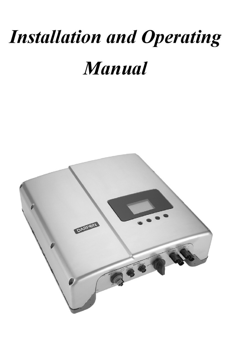
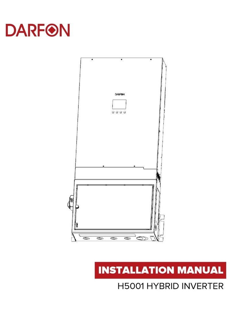
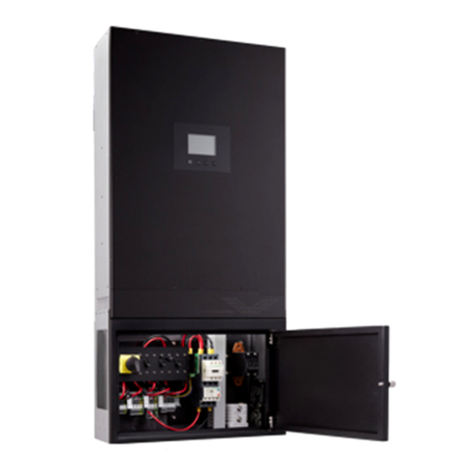
Darfon HB51 User manual

Quick Installation G uide H B 51 Hybrid Inverter
Rev.1 ©2018 Darfon Electronics Corp. 1 | Page
IMPORTANT SAFETY WARNINGS
PLEASE READ ALL INSTRUCTIONS AND CAUTIONARY MARKINGS ON THE UNIT AND THIS GUIDE BEFORE INSTALLING THE INVERTER.
AND, STORE THIS USER MANUAL WHERE IT CAN BE ACCESSED EASILY.
This manual is for qualified personnel. The tasks described in this manual should be performed by qualified personnel only.
Safety Symbols
WARNING. This indicates the risk of electric shock. The presence of high voltage levels may constitute a risk of injury or death to users
and/or installers.
CAUTION. This indicates important information where failure to comply may result in safety hazards or cause damage to this product.
General Precautions
CAUTION. Before installing and using this inverter, read all instructions and cautionary markings on the inverter and all appropriate
sections of this guide. Installing this inverter by licensed electricians only.
CAUTION. Normally grounded conductors may be ungrounded and energized when a ground fault is indicated.
CAUTION. This inverter is heavy. It should be lifted by at least two persons for the safety.
WARNING. Authorized service personnel should reduce the risk of electrical shock by disconnecting AC, DC and battery power from
the inverter before attempting any maintenance or cleaning or working on any circuits connected to the inverter. Turning off controls
will not reduce this risk. Internal capacitors can remain charged for 5 minutes after disconnecting all sources of power.
WARNING. Do not disassemble this inverter yourself. It contains no user-serviceable parts. Attempt to service this inverter yourself may
cause a risk of electrical shock or fire and will void the warranty from the manufacturer.
WARNING. To avoid a risk of fire and electric shock, make sure that existing wiring is in good condition and that the wire is not
undersized. Do not operate the Inverter with damaged or substandard wiring.
WARNING. To reduce risk of fire hazard, do not cover or obstruct the cooling fans.
CAUTION. Do not install the Inverter if it has received a sharp blow, been dropped, or otherwise damaged in any way. If the Inverter is
damaged, call for an RMA (Return Material Authorization).
CAUTION. This inverter is not allowed to operate in parallel. Do not parallel connect more than one unit in AC output connector.
Otherwise, it will damage this inverter.
Manufactured by
Darfon Electronics Corp.
167 Shan-ying Road, Gueishan
Taoyuan 333, Taiwan, (R.O.C.)
Tel: +886 3 2508800
USA Office
Darfon America Corp.
103A Pioneer Way
Mountain View, CA 94041
Tel: +1.650.316.6300
For more information
www.darfonsolar.com
©2018 Darfon Electronics Corp. All rights reserved. All specifications are subject to change without prior notice. Darfon and the Darfon logo are trademarks of Darfon
Electronics Corp. All other trademarks are the property of the respective owners.
WHAT’S IN THE BOX
1
54
2 3
Parts Description Qty
1. HB51 Inverter 1
2. Backplate 1
3. Bracket 2
4. Wood Screws 6
5. Self-drilling Screws 6
Quick Installation G uide H B 51 Hybrid Inverter
Rev.1 ©2018 Darfon Electronics Corp. 2 | Page
PRODUCT OVERVIEW
Communication Ports
RJ12 RS485 S RS485 MRJ45
Dip Switches
Distribution Box
Grid
on
off
Load
on
off
By pass
on
off
PV Input
Grid Input
Load Ouput
AC Input II
(Optional)
Basic Hybrid PV Storage System
RS-485 PIN
DEFINITIONS
RS485 S
RS485 M
1
2
3
4
1
2
3
4
D+
D-
D+
D-
D+
D-
D+
D-
PORT
FUNCTION
RJ45
For H200 External Display
RJ12 (x2)
For Parallel (Stacking) Function
RS485 S (Pin 1&2)
For Data Logger and Remote Access
Dip Switches
For Long Distance Cable Communication
RS485 M (Pin 1&2)
For Battery BMS and Meter
25mm (1.0in)
514mm (20.2in)
150mm (5.9in)
858mm (33.8in)
181mm (7.1in)

Quick Installation G uide H B 51 Hybrid Inverter
Rev.1 ©2018 Darfon Electronics Corp. 3 | Page
MOUNTING THE INVERTER
1. Mount the backplate onto the wall
using at least two screws; one on
each side of the backplate.
2. Install the brackets the inverter.
3. Hang the inverter onto the
backplate.
4. Secure the brackets to the wall using at least two screws; one on each side of the inverter.
DEAD-FRONT COVER
Notes
The dead-front cover must be
removed when making or modifying
connections in the distribution box,
and reinstalled when connections
have been completed.
To remove the dead-front cover, use
the following steps.
Reverse the steps to reinstall the
dead-front cover.
1. Remove the screws from the
dead-front cover.
2. Pull off the dead-front cover.
Mounting Dimensions
Wall Types
Stud: The inverter will need to be mounted to the wall using Unistrut. The Unistrut must be
secured to two studs in the wall. There should be two rows of Unistrut installed: one for the
backplate and the other for the side brackets.
Solid: Use the backplate and mounting dimensions to mark for screw locations.
Notes
The unit cannot be mounted on flammable construction materials.
Allow 20cm (8in) of clearance to the sides and 50cm (20in) to the top and bottom of the unit
for proper air circulation to dissipate heat.
The unit has an IP20 protection rating and a PD2 Pollution Degree rating. The unit is for
indoor applications only and must be mounted in a protected area that is dry, free of
excessive dust and has adequate air flow.
CAUTION. This inverter is heavy (74lb/33.6kg). Mounting should be handled by two
people. Do not place any additional weight onto the inverter.

Quick Installation Guide H B 51 Hybrid inverter
Rev.1 ©2018 Darfon Electronics Corp. 4| Page
CONNECTIONS
System Types: Quick Disconnect Terminals
Installing Conductors in to the Terminal Blocks
1. Push a screwdriver into terminal.
2. Insert the wire into the terminal.
3. Remove the screwdriver.
Installing the Battery Conductors
1. Crimp or bolt ring lugs to the battery
cables.
2. Connect the red cable to the
positive (+) battery terminal.
3. Connect the black cable to the
negative (-) battery terminal.
8mm
(0.3in)
16mm
(0.6in)
Ring Lug Dimensions
Tor que Val ue:
2 to 3Nm
(18 to 26 in-lb)
Torque Val ue:
2 to 3Nm
(18 to 26 in-lb)
Wire/Cable Requirements
GRID
LOAD
BATTERY
Size
8 AWG
8 AWG
2 AWG
Length
--
--
< 3m
Strip 15mm(0.6in) off the AC wires and
battery cables.
WARNINGS
Make sure the circuit breaker is off before making or modifying any connections.
To prevent the risk of electric shock, make sure the ground wire is properly earthed
before operating this unit whether the grid is connected or not.
To reduce the risk of injury, use the recommended wire/cable size.
Do not apply anti-oxidant substance on battery terminals connections are made.
Notes
Order of connections should be Grid, Load, then Battery.
Order of wire connections should be Ground, N, L1, L2.
Connect AC wires according to the labels on the terminal block or your system type.

Quick Installation Guide H B 51 Hybrid inverter
Rev.1 ©2018 Darfon Electronics Corp. 5| Page
WIRING DIAGRAM
TURNING ON THE SYSTEM
1. Turn on the grid breaker if grid is
connected.
2. Turn on the batttery breaker if
batteries are connected.
3. Turn on the Main Switch.
4. If batteries are the only power source,
once the display turns on, hold the
key down until it beeps twice.
5. Turn on the Load Breaker.
Grid
KWH Meter
Main Utility Panel
NGND
Essential Load Panel
N
GND
NL1 L2
NL1 L2
Load Terminals
HB51 Inverter
Battery
Terminals
48V Battery Bank
Micro Inverters
PV Panels
G
G
+
-
Grid Terminals

Quick Installation Guide H B 51 Hybrid inverter
Rev.1 ©2018 Darfon Electronics Corp. 6| Page
TURNING OFF THE SYSTEM
1. Turn off the Main Switch.
2. Turn off the battery breaker.
3. Turn off all AC breakers.
DISPLAY KEYS & ICONS
Power Flow Page w/Load Output
Power Information Page
Power Flow Page w/AC-Couple Input
System Settings Page
KEY FUNCT ION
Enters System Settings
page or confirms selection.
Exits setting mode.
Previous page, previous
item or decrease number.
Next page, next item
or increase number.
ICON
DESCRIPTION
PV Array
Battery Array
Utility
Load
Hybrid Inverter
PC Connection
Warning/Error Codes
Overload Occurred
System Mode Setting
System Time Setting
System Information
Current Time

Quick Installation Guide H B 51 Hybrid inverter
Rev.1 ©2018 Darfon Electronics Corp. 7| Page
CHANGING THE MODE OF OPERATION
1. In System Setting page, press the
key twice.
2. Use the or keys to toggle
between modes and to select.
MODES OF OPERATION
1
Back-Up (Default)
2
Residential
3
TOU Without Battery Feed In
4
TOU With Battery Feed In
5
Remote Control
6
Peak Shave
3. (TOU Modes) Enter “High Price
Duration” in 24-hour notation. Use
the or keys to adjust each digit,
and use the key to set it.
4. When done, press the key. You
will see a message stating the
settings are being updated.
5. When you see “Setting OK!!”
message, pess any key.
6. Manually restart the inverter using
the main switch.
SETTING SYSTEM TIME
1. In the System Setting Page, press
to select “Time Setting”, and then
press .
2. Enter the date (DD/MM/YYYY) and
time (hh:mm:ss). Use the and
keys to adjust each digit, and use the
key to set it.
FIELD
RANGE
Ye a r
2010 to 2100
Month
1 to 12
Day
1 to 31
Hour
0 to 23
Minute
0 to 59
Second
0 to 59
3. When done, press the key. You
will see a message stating the
settings are being updated.
4. When you see “Setting OK!!”
message, pess any key.
5. Manually restart the inverter using
the main switch.

Quick Installation Guide H B 51 Hybrid inverter
Rev.1 ©2018 Darfon Electronics Corp. 8| Page
SETTING BATTERY TYPE
1. In the System Setting Page, press
to enter the page and select to
select Battery Type.
2. Use the or keys to select
Battery Type and to select it.
3. Use the or keys to toggle
between the battery types and press
to select it.
BATTERY TYPE
0
None
1
Lead-Acid
2
Golden Crown
3
Darfon LNMC
4
Panasonic
5
Darfon LFP
4. You will see a message stating the
settings are being updated.
5. When you see “Setting OK!!”
message, pess any key.
6. Manually restart the inverter using
the main switch.
Table of contents
Other Darfon Inverter manuals

Darfon
Darfon H5001 User manual

Darfon
Darfon H5000 User manual

Darfon
Darfon PVI5000 User manual

Darfon
Darfon MIG300 User manual

Darfon
Darfon G640 User manual

Darfon
Darfon H5001 User manual

Darfon
Darfon MIG240UL00 User manual

Darfon
Darfon MIG240 User manual

Darfon
Darfon G320 User manual

Darfon
Darfon H5001 User manual
Popular Inverter manuals by other brands

Telair
Telair TIG 3000D Use and maintenance manual and instructions for installation

Mitsubishi Electric
Mitsubishi Electric FR-E8TR instruction manual

Sinergex
Sinergex Elite 300 user manual

Setec Power
Setec Power SET-IVS9000 Series System manual

Sunforce
Sunforce Pro Series 50060 manual

Solplanet
Solplanet ASW S Series user manual