Boulevard DVP36LPKR-1 User manual

36468-2-0220 Page 1Empire Comfort Systems Inc. • Belleville, IL
INSTALLATION INSTRUCTIONS
FOR USE ON: DVLL(36,48)BP SERIES FIREPLACES ONLY
INSTRUCTIONS MUST BE LEFT WITH THE OWNER FOR FUTURE REFERENCE AFTER INSTALLATION.
CARTON CONTENTS:
• Rear Porcelain Panel
• Left Side Porcelain Panel
• Right Side Porcelain Panel
• Screw Package
• Side Retainer Bracket
(Qty. 2)
TOOLS NEEDED:
• Gloves
• Eye Protection
• 5/16" Hex Driver
PREPARATION
CAUTION
Sharp edges! To avoid injury, wear safety gloves to
install liner.
1. Refertothereplaceinstallationmanualforremoval
oftheBarrierandGlassDoorassembliespriorto
installationoftheporcelainlinerkit.
2.
Removedecorativemediafromhearthandburnercover.
3. Carefullyunpacktheporcelainliners,verifythatall
componentsareincluded,andinspectforhidden
damage,priortoinstallation.
4. RemovethefrontLightCoverbyliftingitupandout,
then set it aside.
5. Ifinstalled,removepaintedlinersfromthereplace.
Removethescrewretainingtherightsidepanelwith
a5/16"nutdrive,andremovethepanel.Repeatthe
processfortheleftsidepanel.See Figure 5 for screw
location.
6. Removethetwoscrewsthatretaintherearlinerpanel
andthenremovethepanel.See Figure 3 for screw
locations.
INSTALLATION
1. ChecktheRearLinerPaneltomakesureitisnot
bowed.NOTE:Thebottomedgehaseighttabsthat
mustbeinastraightlinetomatchupwiththeslots
attherearoftherebox.Checktomakesurethe
insulationonthebackofthepanelremainsinplace
beforeinstallation.
2. InstalltheRearPanelbyaligningtheeighttabsonthe
bottomedgewiththeeightslotsinthebackrearofthe
rebox.NOTE:Theeightslotsarelocatedbehindthe
burnercoverplate.See Figure 1.
SLOTS
TABS
Figure 1
DVLL(36,48)BP SERIES FIREPLACE KITS
DVP36LPKR-1 Porcelain Panel Kit DVP48LKR-1 Porcelain Panel Kit

36468-2-0220Page 2 Empire Comfort Systems Inc. • Belleville, IL
3. Once the tabs are inserted into the slots, rotate the
Rear Panel upward against the back of the rebox.
See Figure 2. Re-install the two previously removed
screws(step6inPreparationsection)throughthetop
tabsoftheRearPaneltosecure. See Figure 3.
Figure 2
Figure 3
4. Check to make sure the insulation is secured to the
backpriortoinstallingtheRightSidePanel.Placethe
RightSidePanelsothetworeartabsalignwiththetwo
slots at the right end of the Rear Panel. See Figure 4.
Figure 4

36468-2-0220 Page 3Empire Comfort Systems Inc. • Belleville, IL
5. Hold the front of the panel against the side retainer
bracket,thenshiftthesidepanelrewardtoengagethe
rear tabs and slots.At the same time, hook the front
angeofthesidepaneloverthesideretainerbracket.
See Figures 5 and 6.
Figure 5
6. Oncethepanelisproperlypositioned,installone5/16
X1/2"screwthroughthetopextendedtabintothepilot
hole located at the top right corner of the Rear liner
paneltosecure.See Figure 6.
TOP VIEW:
FRONT OF SIDE
LINER ENGAGING
THE RETAINER
BRACKET
Figure 6
7. Checktomakesuretheinsulationissecuredtotheback
priortoinstallingtheLeftSidePanel.ToinstalltheLeft
SidePanel,placetheitsothatthetworeartabsalign
with the two slots at the left end of the Rear Panel. Hold
thefrontofthepanelagainstthesideretainerbracket,
thenshiftthesidepanelrewardtoengagethereartabs
and slots.At the same time, hook the front ange of
thesidepaneloverthesideretainerbracket.Oncethe
panel is properly positioned, secure with one 5/16 X
1/2"screwthroughthetopextendedtabintothepilot
hole located at the top left corner of the Rear Panel.
See Figure 7.
Figure 7
8. Check to see that all exposed insulation is tucked
behind the side panels. If necessary, trim away the
excessinsulationaway,usingautilityknife.
9. ReplacetheLightCover.
10.Adddecorativemediaasdesired.
11. ReplaceGlassDoorandBarrierassemblies.

36468-2-0220Page 4
1
2
3
5
4
5
4
INDEX
NUMBER
PART NUMBER DESCRIPTION QUANTITY
SUPPLIED
DVP36LPKR DVP48LKR
1 40500BL 36421BL Panel,RearLiner 1
2 36422BL 36422BL Panel,LeftLiner 1
3 36423BL 36423BL Panel,RightLiner 1
4 35632 35632 Bracket,SidePanel 2
5 R2737 R2737 Screw,#10X1/2" 6
N/S R11285 (2) R11286 (3) Insulation-RearPanel 3
N/S R11970 R11970 Insulation-SidePanel 2
N/S - Not Shown
www.empirecomfort.com
Empire Comfort Systems Inc.
Belleville, IL
Ifyouhaveageneralquestion
aboutourproducts,pleasee-mail
usat[email protected].
Ifyouhaveaserviceorrepair
question,pleasecontactyourdealer.

36468-2-0220 Page 1Empire Comfort Systems Inc. • Belleville, IL
INSTRUCTION D’INSTALLATION
À UTILISER SUR : FOYERS SÉRIE DVLL(36,48)BP SEULEMENT
APRÈS LE MONTAGE, LE FEUILLET D’INSTALLATION DOIT ÊTRE
LAISSÉ AU PROPRIÉTAIRE POUR CONSULTATION ULTÉRIEURE.
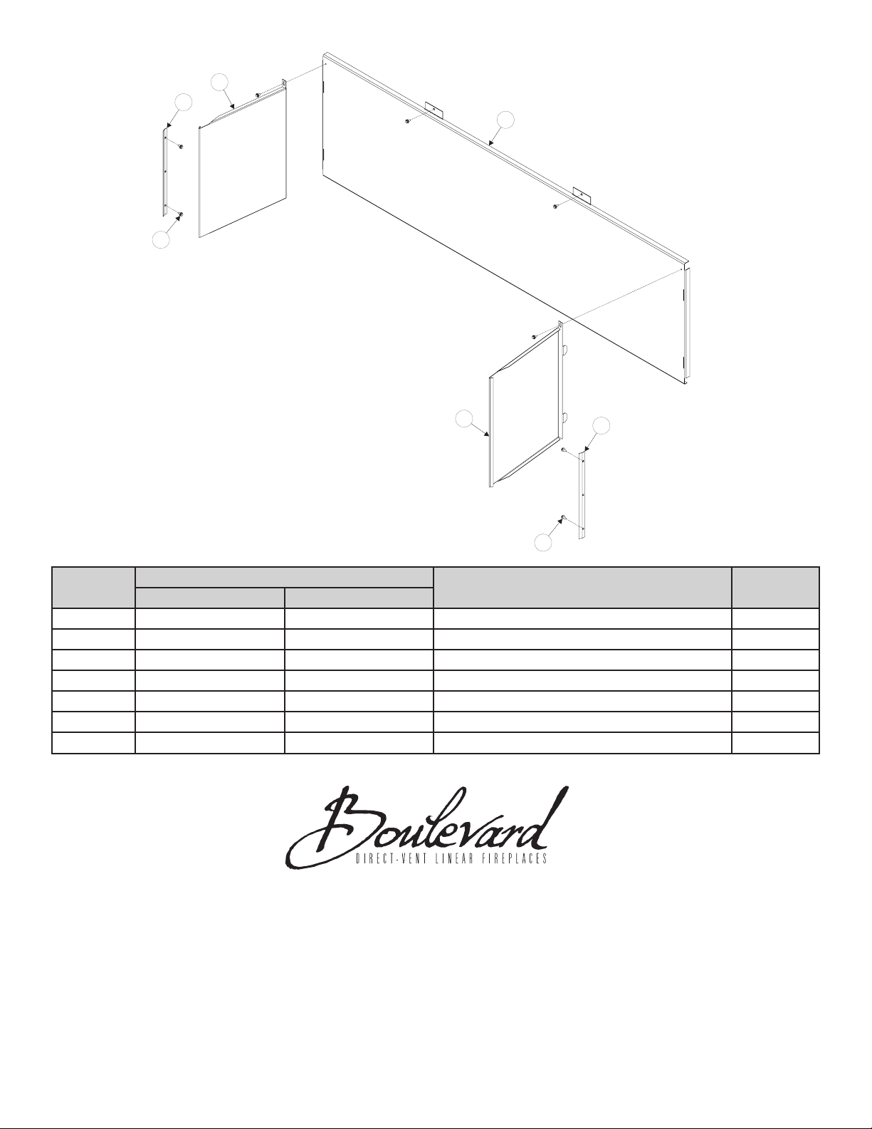
CONTENU DE L’EMBALLAGE :
• Panneaudeporcelaine
arrière
• Panneaudeporcelaine
gauche
• Panneaudeporcelainedroit
• Sac de vis
• Supportsderetenue
latéraux(2)
OUTILS REQUIS :
• Gants
• Protectionoculaire
• Tourne-écrouhex.
5/16po
PRÉPARATION
ATTENTION
Bords tranchants! Pour éviter les blessures, porter
des gants de sécurité lors du montage des garnitures.
1. Pourdéposerl’écranetlaportevitréepour
l’installationdesgarnituresdeporcelaine,seréférerau
manueld’assemblagedufoyer.
2.
Déposeretsortirlespiècesdécorativesetlecouvercle
dubrûleurdel’âtre.
3. Déballersoigneusementlespanneauxdeporcelaine
etvérierquetoutlematérielestprésentet,avant
l’installation,conrmerqu’aucunepiècen’est
endommagée.
4. Déposerlecouvercleavantducompartiment
d’éclairageenlesoulevantetlemettredecôté.
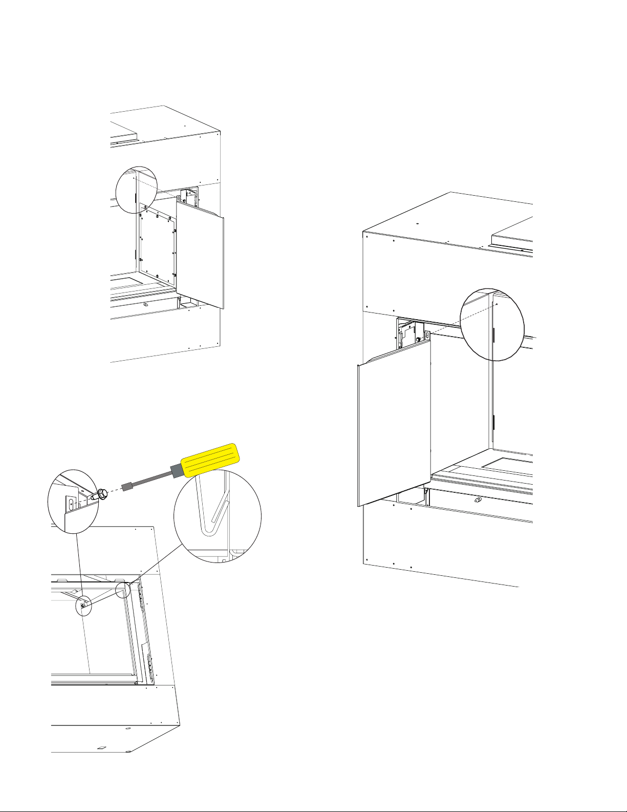
5. Silefoyeradespanneauxpeints,retirez-lesdel’âtre.
Àl’aided’untourne-écroude5/16po,déposerlesvis
demaintiendupanneaucôtédroitetlesortirdel’âtre.
Répéterpourlepanneaugauche.Pourl’emplacement
delavis,voir la Figure 5.
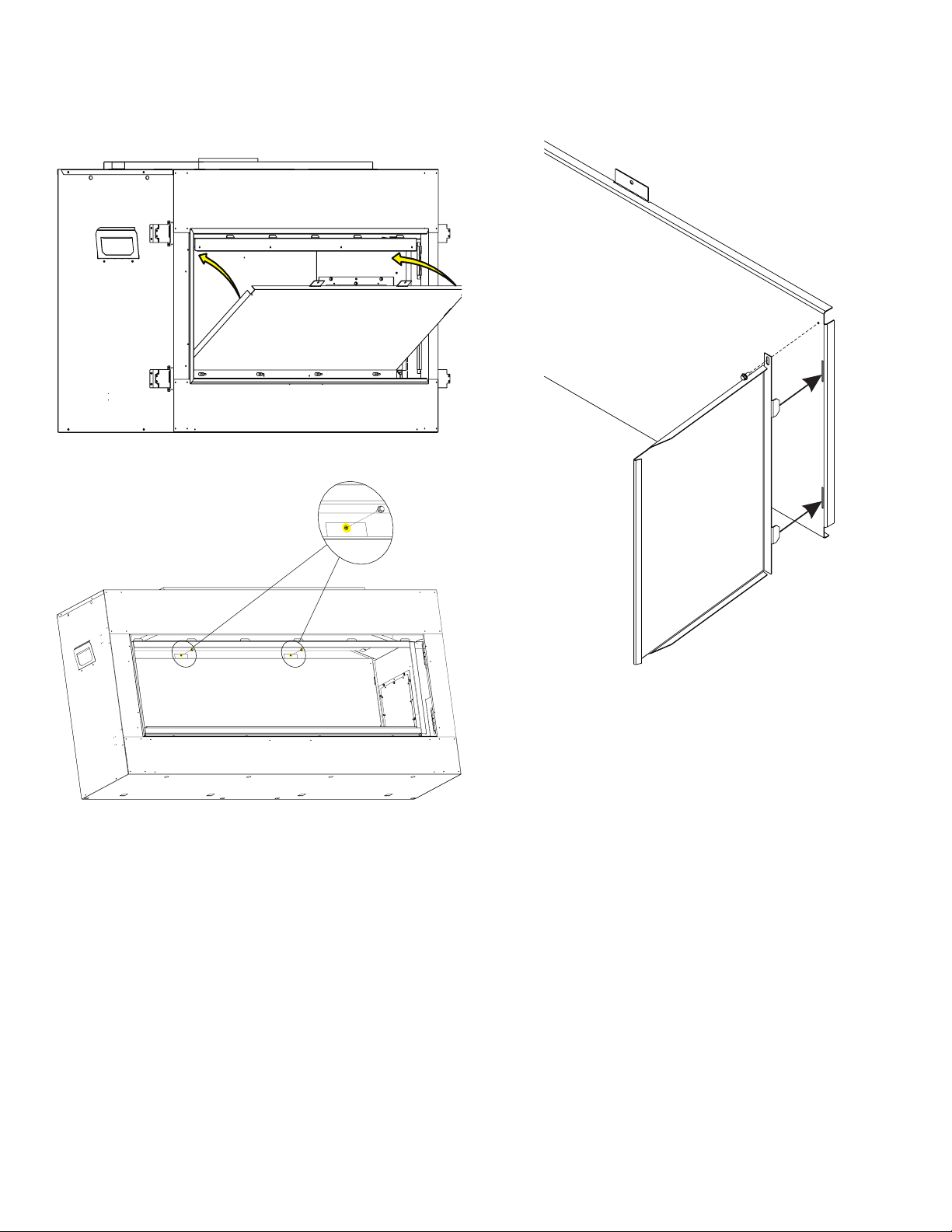
6. Déposerlesdeuxvisderetenuedupanneaude
garniturearrièreetsortirlepanneaudel’âtre.Pour
l’emplacementdesvis,voir la Figure 3.
INSTALLATION
1. S’assurerquelasurfacedupanneau-garniture
arrièreestplanesansgondolageousansêtre
arquée.REMARQUE :Lebordinférieurpossède
huitlanguettesquidoiventêtrealignéespourpouvoir
êtreinséréesdanslesfentesdanslefonddel’âtre.
S’assurerquel’isolantdemeureenplaceaudosdu
panneaulorsdesoninsertion.
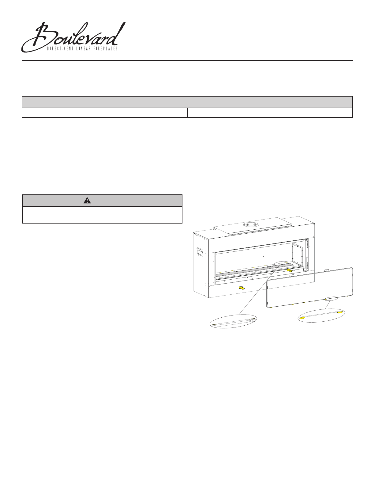
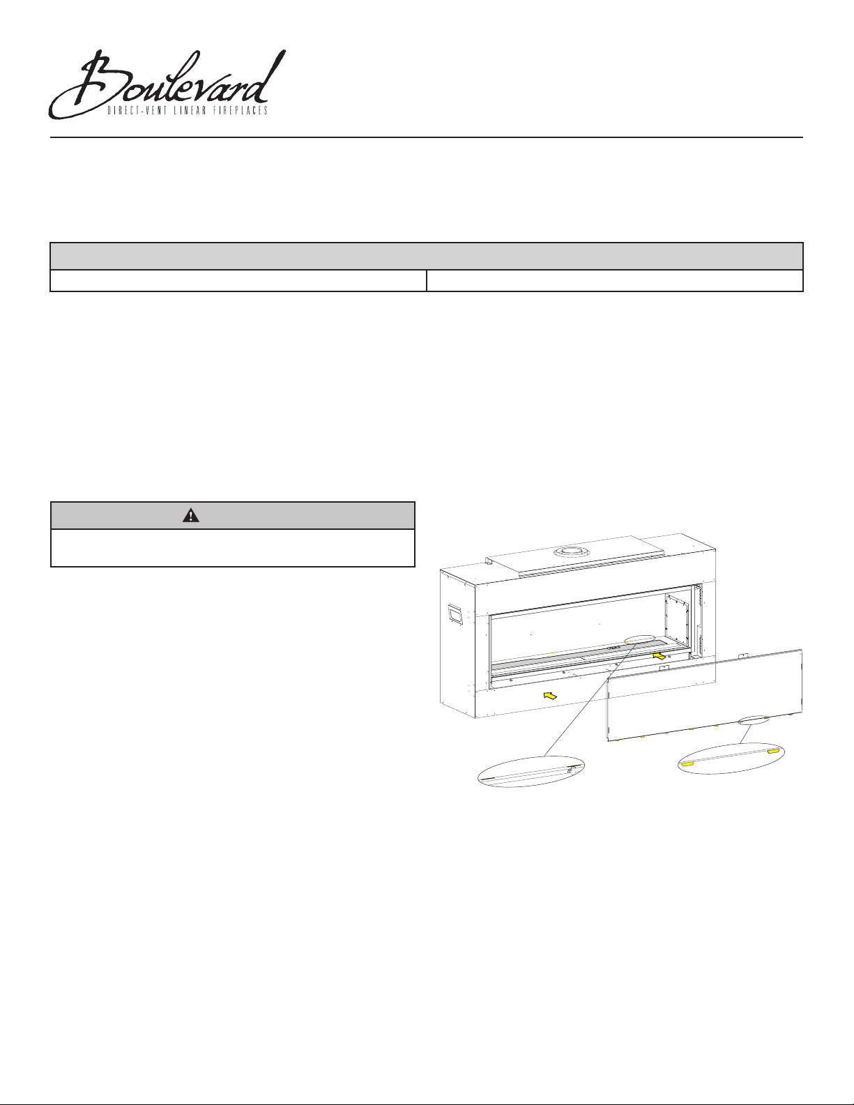
2. Monterlepanneauarrièreenalignantseshuit
languettessurlesfentesarrièreaufonddel’âtre.
REMARQUE :Leshuitfentessetrouventderrièrela
plaquerecouvrantlebrûleur.Voir Figure 1.
FENTES LANGUETTES
Figure 1
TROUSSES POUR FOYERS SÉRIE DVLL(36,48)BP SEULEMENT
Trousse de panneaux de porcelaine DVP36LPKR-1 Trousse de panneaux de porcelaine DVP48LKR-1

36468-2-0220Page 2 Empire Comfort Systems Inc. • Belleville, IL
3. Après avoir inséré les languettes dans les fentes,
faites pivoter le panneau vers l’arrière de l’âtre. Voir
Figure 2.Àl’aidedes deux vis déposées à l’étape 6
(section Préparation), xer le panneau en les vissant
dansleslanguettes supérieures trouéesdupanneau.
Voir Figure 3.
Figure 2
Figure 3
4. Avantlemontagedupanneaulatéraldroit,s’assurerque
sondosisolantestbienenplace.Alignerlepanneaude
droitepourinsérersesdeuxlanguettesarrièredansles
fentesdupanneauarrière.Voir Figure 4.
Figure 4

36468-2-0220 Page 3Empire Comfort Systems Inc. • Belleville, IL
5. En tenant le panneau par l’avant, le pousser contre
lesupportderetenuelatéraletleglisserversl’arrière
pourinsérer seslanguettesdanslesfentesarrière et
puisaccrocherlabrideavantdupanneaulatéralsurle
supportderetenue.Voir Figures 5 et 6.
Figure 5
6. À l’aide d’une vis 5/16 X 1/2 po, xer en dernier le
panneau par sa languette trouée sur le dessus. Voir
Figure 6.
VUE DU HAUT :
DEVANT DU
PANNEAU LATÉRAL
S’EMBOÎTANT SUR
LA BARRE DE
RETENUE
Figure 6
7. Avantlemontagedupanneaulatéralgauche,s’assurer
que son dos isolant est bien en place. Aligner le
panneaudegauchepourinsérersesdeuxlanguettes
arrièredanslesfentesdupanneauarrière.Entenant
lepanneauparl’avant,lepoussercontrelesupportde
retenue latéral et le glisser vers l’arrière pour insérer
seslanguettesdanslesfentesarrièreetpuisaccrocher
la bride avant du panneau latéral sur le support de
retenue.Àl’aided’unevis5/16X1/2po,xerendernier
lepanneauparsalanguettetrouéesurledessus.Voir
Figure 7.
Figure 7
8. S’assurerqu’iln’yapasd’isolantdemeurantexposé.Au
besoin,couperl’excédantàl’aided’unelameutilitaire.
9. Remettrelecouvercleducompartimentd’éclairageen
place.
10.Reposerlespiècesdécorativesdésirées.
11. Reposerlaportevitréeetl'écransurlefoyer.

36468-2-0220Page 4
1
2
3
5
4
5
4
NUMÉRO DE
REPÈRE
NUMÉRO DE PIÈCE DESCRIPTION QUANTITÉ
FOURNIE
DVP36LPKR DVP48LKR
1 40500BL 36421BL Panneau-garniturearrière 1
2 36422BL 36422BL Panneau-garnituregauche 1
3 36423BL 36423BL Panneau-garnituredroit 1
4 35632 35632 Barrederetenuedespanneauxlatéraux 2
5 R2737 R2737 Vis,#10X1/2po 6
N.M. R11285 (2) R11286 (3) Isolant-panneauarrière 3
N.M. R11970 R11970 Isolant-panneaulatéral 2
N.M.=Nonmontré
www.empirecomfort.com
Empire Comfort Systems Inc.
Belleville, IL
Pourtoutequestiongénéraleconcernantnos
produits,veuilleznousenvoyeruncourrielà
Pourtoutequestiond’entretienouderéparation,
veuillezcontactervotreconcessionnaire.
Table of contents
Languages:
Other Boulevard Fireplace Accessories manuals
Popular Fireplace Accessories manuals by other brands

IHP
IHP CHAROAK35 installation instructions

European Home
European Home Scaffold 42 installation guide

SimpliFire
SimpliFire SF-FORMAT36 Service manual

Travis Industries
Travis Industries 96100150 manual

Valor
Valor L3 installation manual

Empire Comfort Systems
Empire Comfort Systems FBB21 installation instructions

Town & Country Fireplaces
Town & Country Fireplaces TC30 Black Diamond instructions

Valor
Valor ZERO CLEARANCE KIT installation instructions

Travis Industries
Travis Industries shield 6015 quick start guide

Napoleon
Napoleon FPWI3 installation instructions

Miles Industries
Miles Industries 1500I Installation

Napoleon
Napoleon ROGUE SE625-1 Quick assembly guide