Boyd E3010CB Operating manual
1
REV D
December 3, 2014
DOC. 9816
Product Informaon / Technical Service Manual
E3010CB / M3010CB Treatment Chair
12900 44th Street North
Clearwater, Florida 33762
800-255-2693 * 727-561-9292
FAX: 727-561-9393 SALES
FAX: 727-561-1682 SERVICE

2
REV D
December 3, 2014
DOC. 9816
Table of Contents:
Title Page
Table of Contents
Introducon
Applicaon of Product
Warranty Informaon
Safety Warning Symbols
Safety Tips / Precauons
About Your Chair
Descripon of Product Line
Standard Safety Features
General Product Informaon
Product Specicaons
Transport & Disposal
Unpacking and Power Requirements
Installaon Instrucons
Operaon Instrucons
Inializaon of Chair Motors
Programming Instrucons
General Operaon Instrucons
General Maintenance and Care
Cleaning Instrucons
Service Informaon
Schemac Wiring Diagrams
Parts Breakdown
Li Base Assembly
Chair Frame Assembly
Oponal Armrest Assembly (LH and RH)
Light Post Assembly
Upholstery
Upholstery Installaon and Removal
Troubleshoong Guide
Electromagnec Immunity Data
1
2
3
4
5
6-9
10
11
12-14
15
16-18
19-26
27
28
29-32

3
REV D
December 3, 2014
DOC. 9816
Intended Use and Application of Product
This product is designed to comfortably posion paents during dental examinaons and procedures. The chair back and base
are adjustable to allow the most ergonomic working posion for the doctor and their assistant(s).
Warranty Statement
All BOYD manufactured products are warranted against defects in material or workmanship only. No other warranes are
expressed or implied. This warranty shall extend for three (3) years for parts and one (1) year for labor. The BOYD warranty only
covers products manufactured by BOYD. Products distributed, not manufactured, by BOYD carry the stated manufacturer’s
warranty.
The warranty period commences upon invoice date of the equipment. Wrien noce of breach must be submied to Boyd
Industries, Inc. within this period. BOYD reserves the right to repair or replace, at its sole discreon, the item in queson.
Warranty is voided if items are misused or product is improperly maintained or installed. The warranty does not cover any
alteraon of the product from its original condion or if product is used in any way other than the product’s design intent.
An authorized service technician must perform all service and maintenance. Any warranty labor must be rst approved by BOYD.
Failure to coordinate warranty service may result in denial of warranty repair. Wrien log and receipts for service must be
maintained to validate the warranty on BOYD manufactured products.
No claim for consequenal damages will be allowed. Freight damage or mishandling by any third party will not be considered a
warranty item. Improper installaon by a third party causing damage to the equipment is not a warranty item.
Introducon
Congratulaons
on your purchase of Boyd Orthodonc
Exam / Treatment Chairs
Boyd Industries, Inc. has spent years designing and developing the best orthodonc products available in the world today. The
following features make your Boyd chair the most advanced and funconal orthodonc chair available in the market:
All steel frame construcon
Motorized back with synchronized leg and canlever li base
14” vercal stroke
Three (3) operator designated pre-set posions
Auto return to HOME switch
Choice of extendable headrest
Snap in / snap out upholstery
Chair back side membrane controls
Smooth, quiet, low voltage D/C motors
4
REV D
December 3, 2014
DOC. 9816
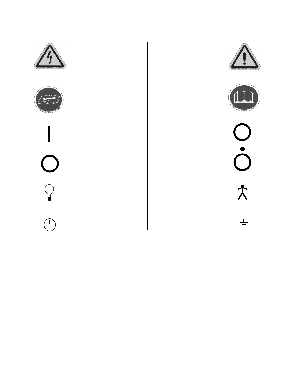
Safety Warning Symbols
Cauon: Risk of Electrical Shock Cauon: General Danger
Informaonal: Read Operator’s
Manual
Informaonal: Read Technical
Manual Before Servicing
Main Power On Main Power O
Accessory Power On
Accessory Power O
Light
Protecve Earth Ground
Type B Equipment
Earth Ground
•

5
REV D
December 3, 2014
DOC. 9816
Safety Tips and Precauons
This product has been designed and tested with your safety in mind. Improper use can result in electric shock or other
physical injuries. Do not defeat the safeguards that have been designed into this product. Please read and observe the
following safety points when installing and operang this product. Save this manual and all supplemental literature for future
reference. Observing precauons listed in this booklet will help you get many years of service and safe operaon from your
equipment.
1. Medical Electrical equipment requires special precauons regarding EMC and needs to be installed and put into service according to
the EMC informaon provided in this manual.
2. Portable and mobile RF communicaons equipment can aect medical electrical equipment.
3. The use of accessories, transducers, and cables other than those specied, may result in increased emissions or decreased immunity
of the E3010CB / M3010CB Chair. Refer to emissions & immunity data on pages 29-32.
4. Read instrucons:
All safety and operang instrucons should be read before this product is operated.
5. Follow instrucons:
All use and operang instrucons should be followed.
6. Owner’s manual:
Retain safety and operang instrucons for future reference.
7. Heed warnings:
Adhere to all warnings labeled on equipment and in owner’s manual.
8. Accessories:
Use only accessories from Boyd Industries, Inc. catalog on this chair. Third party accessories will void the warranty and may be
unsafe.
9. Cleaning:
Use mild detergent in water on all painted surfaces and plasc parts. Use only cleaners specically designed for cleaning
disinfecng vinyl upholstery. Refer to vinyl manufacturer’s documentation for specific cleaning information.
10. Line cord:
This product is equipped with a polarized, grounded, alternang current line plug. This plug will t into the power outlet only
one way. This is a safety feature. If you are unable to insert the plug into your outlet, contact a local electrician to correct the
problem with the A/C outlet.
11. Power cord protecon:
Power supply cords should be routed so that they are not walked on or pinched by any other equipment placed upon or against
them. Be sure that cords aached to plugs on the chair will not get pinched as they exit the equipment.
12. Liquid and object entry:
Do not intentionally pour liquids of any kind on this equipment or push objects of any type into openings as they could touch
moving parts or dangerous voltage points inside equipment which could cause fire hazard, electric shock and/or bodily injury.
13. Servicing:
Do not attempt to service this product yourself. This action will void any warranties. Opening covers could expose you to
dangerous current and mechanical pinch points. Service should only be performed by qualified service personnel. Contact Boyd
Technical Services Department for authorized technicians in your area.
14. Damage or failures requiring service:
Unplug equipment from power source and refer to a qualified service technicians if any of the following occur:
Power supply cord is damaged.
Liquid has been spilled into equipment.
Objects have fallen into equipment.
Equipment has been exposed to rain or water.
Equipment has been dropped or damaged.
Equipment shows significant change in operation.
Equipment does not operate normally.
15. Replacement parts:
Contact Boyd Technical Services Department to order approved replacement parts. Unauthorized substitutions could result in
electrical shock, fire hazard and/or bodily injury.
16. Safety checks:
Upon the completion of any service to equipment, service personnel must perform safety checks to insure that all equipment
is functioning properly and safely.
17. Heat / Open flame:
Equipment should be installed away from heat sources such as radiators, heat registers, stoves, or other products that produce
heat or open flames. There should be no smoking in a room where this equipment will be operated or stored.

6
REV D
December 3, 2014
DOC. 9816
Descripon of Product Line
Model: E3010CB / M3010CB
Features: Power Back with synchronized leg
Canlever Style Li Base
Hand Controls
Foot Control with Programming (oponal)
Standard Safety Features
About Your Chair
1. Power Supply Chair is circuit breaker protected.
2. Hand Controls Hand Controls are located on both sides of the back secon. Pressing any motor control funcon switch
will cancel any automac movement funcon.
3. Foot Controls (Oponal) Foot Control is integrated into the base assembly. Pressing any motor control funcon switch will cancel
any automac movement funcon.
4. Covers and Guards Covers and guards are designed to prevent possible injury from moving parts.
5. Base Safety Boom cover on the base li arm assembly is a safety stop device. Any obstrucon under the li arm
assembly will trip the safety system which will stop all chair movements. Chair will not operate unl
the obstrucon is removed.

7
REV D
December 3, 2014
DOC. 9816
General Product Informaon
Frame Welded steel with powder coated nish
Upholstery Standard upholstery is vinyl
Upgrades are available
Movement CB Base: Canlevered Li - 14.00” (355mm)
Back / Synchronized Leg: Electric Actuator
Net Weight E3010CB / M3010CB: 297 lbs (135 kg)
Electrical 24V D/C low voltage motors
Microprocessor controlled
Chair operates at 24V D/C
Power Supply 115VAC 60HZ 10A
Protecon Class: I
Electrical Shock Type: B
Liquid Protecon Ordinary equipment (IPXO)
Flammable Gases Not suitable for use in the presence of ammable gases or where such gases may accumulate in
concentraon. (Closed Space)
Operaon Mode Intermient duty cycle:
10% - 2 minutes On / 18 minutes O
Indoor use only
Operang / Transportaon Temperature: 5° C to 50° C (41° F to 122° F)
Temperature Relave Humidity: 20% to 90% @ 30° C - Not condensing
Storage Temperature Temperature: -10° C TO 50° C (14° F TO 122° F)
Relave Humidity: 20% to 90% @ 30° C - Not condensing
Weight Capacity 500 lbs (228 kg) Subject to normal weight distribuon
Note: Do not sit on back or foot end of seat secon. These secons are not designed to support the
full weight of paent. Do not li or slide chair using back secon or seat upholstery.
About Your Chair (connued)

8
REV D
December 3, 2014
DOC. 9816
32.75 TO
TOP OF
SEAT
FRAME
25.75
66.25
28.25
WITH
ARMS
24.25
w/ o ARMS
58.13
8
14
18.75 TO
TOP OF
SEAT
FRAME
11.75
Note: Headrest height is adjustable
approximately 6”.
Product Specicaons
E3010CB / M3010CB
About Your Chair (connued)
TOP VIEW
SIDE VIEW
FULL UP POSITION
SIDE VIEW
FULL DOWN POSITION

9
REV D
December 3, 2014
DOC. 9816
Transporng of Chair
When transporng the chair:
Chair base must be in full down posion, and the chair back must be in full up posion.
Chair frame must be secured to the chair base.
Remove the chair power cord.
Secure or remove dental light and any accessories.
Move equipment by gently lng it on the side edge of the oor plate by liing on under side of seat only enough to be able
to slide onto proper moving equipment. Do not use back secon or seat upholstery to li or move chair. Never aempt to
move chair alone and always use proper liing techniques to avoid physical injury.
Chair should be secured to transporng equipment and/or transporng vehicle.
Disposal of Equipment
Disposal of Boyd equipment:
Boyd chairs are designed and built to last and provide ecient and safe service for many years. The expected service life of the
E3010CB / M3010CB is 15 years. When the me nally comes to rere the chair, please dispose of the equipment according to
statutory and regulatory requirements. Circuit boards and electrical cabling should be recycled as electrical salvage. Plasc parts
should be recycled accordingly. Any material unsuitable for recycling should be disposed of appropriately.
About Your Chair (connued)

10
REV D
December 3, 2014
DOC. 9816
Unpacking
Preassembly Check: Open shipping cartons carefully and check to see that all parts are received and have not been
damaged during shipping.
Unpacking Chair: Carefully remove two (2) fasteners securing chair to pallet using nut driver supplied with order.
Slide chair from pallet to proper moving equipment and secure to move chair to nal installaon
locaon. Take care using any sharp objects or tools to avoid damage to upholstery or painted
parts.
Cauon: Chair should be lied from below main seat frame. Do not at anyme move chair by liing on
back or seat upholstery. Use proper liing techniques to avoid injury.
Contents:
Complete chair: Chair and Base assembled with upholstery
Headrest
Four (4) anchors (Used to secure to oor)
A/C power cable
Accessories Opons (I.E. Arms, Light post, etc.)
Owner’s / Operator’s manual
(Note: Accessories may be packaged separately)
Power Requirements
Check chair idencaon label located on electrical panel for required voltage specicaons. Connect chair to
hospital grade receptacle only.
115-120 VAC ~ 60 Hz
10 Amp
Unpacking and Power Requirements

11
REV D
December 3, 2014
DOC. 9816
Locaon: Full size templates are available upon request for laying out location of chair and utilities (if required) prior to actual
installation.
Cauon: Base must be anchored to floor. Failure to do so may result in serious bodily injury to operator and/or patient and
could cause unwarranted product damage. Chairs not properly anchored do not meet warranty requirements.
1. Posion chair as desired. Drill holes in oor through mounng holes. Anchor base to oor with four (4) anchors & screws
provided.
Cauon: To prevent possible injury or damage, do not drill through carpeting. Cut away carpeting at anchor hole locations.
2. Make ulity connecons in oor in front of base (if required).
3. Ensure safety covers are in place and removable upholstery is secure. Shiing may have occurred during handling or
shipping.
4. Plug chair into approved A/C outlet. This chair required 115V A/C.
5. Turn main power switch ON (C1) located on the electrical panel at
front of base.
6. Perform initialization procedure. (see below)
7. Perform safety and operaonal check.
8. If chair does not operate correctly, see the “Troubleshoong”
secon of this manual.
9. When chair is operang correctly, turn power o unl chair is to be
used.
10. For upholstery removal and installation, refer to page 27.
Inializaon Procedure
1. Run the back motor to its full down position.
2. Run the base motor to its full up position.
3. Press and release HOME button and allow both motors to fully return to the patient exit position (back full up and base full
down).
Chair is now initialized and ready for use.
Installaon Instrucons
Fully Assembled Chair
Model: E3010CB / M3010CB
A/C Input to Chair
Main Power Switch (C1)
Front View
of Chair
Home
Base Up
Back Down
Hand
Control
Foot Control
(Oponal)
Back Down Base Up
Home Home

12
REV D
December 3, 2014
DOC. 9816
E3010CB / M3010CB Series Chair
Programming Instructions:
1. Read these instrucons completely before you begin programming.
2. Using the chair up and down or back up and down controls, posion the chair as desired.
3. Wait at least three (3) seconds and push and hold the save buon (S) for four (4) seconds, (system will issue a confirmation
beep). Within two (2) addional seconds, push the buon of the desired posion (i.e. “1”,”2”,”3”) The system will issue a
second confirmation beep. This will automacally replace any pre-programmed posion.
4. Reposion chair and recall that posion to insure that it has been programmed correctly.
5. Repeat steps 2, 3, and 4 unl all desired posions are programmed. You can save up to three (3) posions.
6. HOME is a preset posion that cannot be changed.
The programmed posions can be aained at any me and from any posion.
General Operating Instructions:
1. Before operang chair, watch for any obstrucons under chair.
Do not allow small children to play on, around, or underneath chair or base.
Do not allow service animals on or underneath chair or base.
Any obstrucon that may hinder normal movement of any part of the chair should be cleared away before inializing
any posioning of the chair.
Check to be certain that all people are clear of the chair before operang chair funcons.
2. Chair should be turned OFF at main power switch (C1) any me it is not being used.
Operang Instrucons
Save
Hand
Control
Posion 1
Posion 2
Posion 3
Position 1
Save
Foot Control
(Oponal)
Posion 2
Posion 3

13
REV D
December 3, 2014
DOC. 9816
E3010CB / M3010CB Series Chair
Save
Home
Posion #1
Posion #2
Posion #3
Home
Oponal Foot Control
P/N 15-1195 / 15-1195B
Base Up/DownBack Up/Down
Note: Chair movement can be stopped by depressing any direconal control (i.e. back up / back down,
base up / base down, or any programmed posion).
Standard: Foot Control E3010CB
Oponal: Foot Control M3010CB
P/N 15-1195 115V.
Operang Instrucons (connued)
BASE UP/DOWN:
Press and hold to move chair
upward or downward
BACK UP/DOWN:
Press and hold to move back
upward or downward
POSITION #1:
Press to move to position #1
See separate instructions
POSITION #2:
Press to move to position #2
See separate instructions
POSITION #3:
Press to move to position #3
See separate instructions
HOME:
Returns chair and base to
Original entrance / exit
position
(back up / base down)
Press once to activate.
SAVE:
Used for programming
See separate instructions
Hand
Control
14
REV D
December 3, 2014
DOC. 9816
E3010CB / M3010CB Series Chair
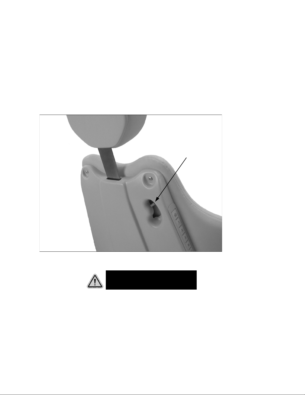
Headrest Release
(All Models)
Headrest height adjustment:
To lower or raise the headrest; support the headrest with one hand and push the release lever down with the other.
Lower or raise the headrest to desired height.
Release the lever.
The headrest bar will lock in desired position.
Cauon:
It is recommended that the headrest height is adjusted before lowering the chair back.
Headrest
Release Lever
Be sure to support the patient’s head and neck at all times when adjusting the headrest position with patient seated.
Operang Instrucons (connued)

15
REV D
December 3, 2014
DOC. 9816
Infecon Control
All established infection control policies should be followed. All work surfaces and patient contact surfaces should be disinfected
between patients and at the end of the day using a product that is EPA registered as ‘hospital disinfectant’ and labeled for
‘tuberculocidal’ activity.
Two (2) such products are:
Tri-cide (800)342-3096
Medocadcio (800)777-7072
Technical Service
For parts, service, or technical information contact:
Boyd Industries, Inc.
12900 44th Street North
Clearwater, Florida USA 33762
tel: 1-727-561-9292
1-800-255-2693
Opon 1 (Tech Service)
fax: 1-727-573-1682
It is recommended that the chair and equipment be thoroughly cleaned and disinfected in accordance with the appropriate FDA
guidelines. Use only cleaners and disinfectants approved for cleaning vinyl. Do not use strong or harsh cleaners as they may cause
the vinyl color to fade. Apply the cleaner to a towel, not directly to the vinyl. Refer to vinyl manufacturer’s data on Boyd’s website
for cleaning products. (www.boydindustries.com/support)
General Maintenance and Care
Cleaning

16
REV D
December 3, 2014
DOC. 9816
Schemac Wiring Diagrams
115 VAC Electrical Component Diagram, E3010CB / M3010CB
Foot Control and
Cable are Oponal

17
REV D
December 3, 2014
DOC. 9816
115 VAC Electrical Schematic, E3010CB / M3010CB
All foot control switches
are momentary N.O.
Schemac Wiring Diagrams (connued)

18
REV D
December 3, 2014
DOC. 9816
Electrical Parts Lisng
Linak CB6 Control, 115V
Switch, Circuit Breaker, 10A, 115V
Electric Distribution Box, 115V
Linak DJB
Foot Control, 2 Pedal (Optional)
T-Cable, Linak
Coiled Cable, Foot Control (Optional)
A/C Power Cord, 115V, 10ft
Harness, Electrical Box
Cable, Safety Switch
Safety Switch
Harness, Electrical Box
CB6 Power Cable
Cable, Membrane Switch Part “A”
Cable, Membrane Switch Part “B”
Linak Motor Extension Cable
Cable Connector Locking Clip
Back Motor, Linak LA31
Base Motor, Linak LA34
Membrane Switch Pad
Fuse Holder
Fuse, 2A (For 115V Chairs)
Cable, A/C Outlet
A/C Outlet Assembly, 115V
Switch, Position 1 (Foot Control Opt)
Switch, Position 2 (Foot Control Opt)
Switch, Position 3 (Foot Control Opt)
Switch, Save (Foot Control Opt)
Switch, Base Down (Foot Control Opt)
Switch, Base Up (Foot Control Opt)
Switch, Back Down (Foot Control Opt)
Switch, Back Up (Foot Control Opt)
Switch, Auto Return (HOME) (Foot Control Opt)
1
2
3
4
5
6
7
8
9
10
11
12
13
14
14
15
16
17
18
19
20
21
22
23
SW1
SW2
SW3
SW4
SW5
SW6
SW7
SW8
SW9
10-4580
10-2250
15-0910
10-4546
15-1195
15-1182
15-0115
10-1413
15-1179
15-1106
10-2322
15-1181
10-1088
15-1172A
15-1172B
10-4547
10-4549
10-4552
10-4550
15-1170
10-0338
10-0280
15-1117
15-2351
10-2277
10-2277
10-2277
10-2277
10-2273
10-2273
10-2273
10-2273
10-2277
(Ref. Diagrams on pages 16 and 17)
Schemac Wiring Diagrams (connued)

19
REV D
December 3, 2014
DOC. 9816
E3010CB / M3010CB Base
View “A”
Oponal Foot
Control and Cable
Parts Breakdown

20
REV D
December 3, 2014
DOC. 9816
E3010CB / M3010CB Base
View “B”
Base
Motor
Back
Motor
Control
Cable
AC
Input
Parts Breakdown (connued)
This manual suits for next models
1
Table of contents
Other Boyd Indoor Furnishing manuals


Popular Indoor Furnishing manuals by other brands

deVRIES
deVRIES Avoy Assembly instructions

Whalen
Whalen Dulzura SPUS-DZMF-LBM manual

dobue MOVELARIA
dobue MOVELARIA CRETA 300016 Assembly instruction

Acme Furniture
Acme Furniture BD01375 Assembly instructions

Glacier
Glacier LS42DB Assembly instructions

Next
Next HEARTS AND STARS 355885 Assembly instructions


