BPE PowerDepot BPE-LFP-5.12-WM User manual

USER MANUAL
BPE PowerDepot 5.12kWh
Wall Mounted Lithium
Battery

TABLE OF CONTENTS
01 SAFETY INFORMATION
General Safety
Personal Safety
Electrical Safety
Environment Safety
05PRODUCT INFORMATION
Battery Overview
Apperance
Front Panel
Dimensions
Capacity Options
Parallel Communication
Recommended Settings
12WARNINGS
12SPECIFICATIONS
01
01
02
04
05
05
06
10
10
11
11
1
1 - SAFETY INFORMATION
1.1 General Safety
Please fully read the safety precautions in this document and observe all the safety instructions
on the equipment.
The “DANGER”, “WARNING”, and “NOTICE” statements in this document do not cover all the
safety instructions. They are only supplements to the safety instructions.
In order to ensure human safety and equipment functionality, use the appropriate symbols
below to identify any potential issues with the equipment. You must fully understand and
comply with the information to avoid personal injury and property damage.
DANGER
WARNING
NOTICE
DANGER indicates a hazardous situation which must be addressed.
WARNING indicates a hazardous situation which, if not resolved
could result in damage or void the warranty.
NOTICE indicates normal operating situation which some functions
may need addressing in order to ensure optimal battery use.
Follow local laws and regulations when installing, operating or maintaining the
equipment. The safety instructions in this document are only supplements to local
laws and regulations.
1.2 Personal Safety
Personal Requirements
Personnel who plan to install or maintain battery equipment must be trained,
have understood all the necessary safety precautions and be able to perform all
operations correctly.
Only qualified professionals or trained personnel are allowed to install, operate
and maintain the equipment.

Electrical Danger Voltage exists when the battery is powered on. Only qualified
engineers are permitted to operate.
Earth Connector Earth Connection
DC Positive and
Negative Connectors Identify positive and negative connectors of DC power source.
CE mark The product meets CE certification.
WEEE Tag Battery must be disposed of appropriately.
Recycle Battery can be recycled
2
Personal Safety
»Do not install the battery in a location accessible to children or animals.
»Do not touch the battery when charging as it may be hot.
»Do not touch the battery terminals.
»Do not stand, lean or sit on the battery.
DANGER
1.3 Electrical Safety
Battery Symbols
There are some electrical symbols on the battery which relate to electrical safety.
Please make sure you have fully understood them before installation.
3
Electrical Safety
»Before installation, ensure that the equipment is intact or electric shock/fire
may occur.
»Do not connect or disconnect power cables when the battery is switched on as
this may cause electric arcs and sparks which can lead to fire or personal injury.
»Before connecting a power cable, check the positive and negative connectors
are correct.
»Do not parallel connect different types of batteries.
»Do not connect the battery with AC power directly.
»Do not connect the battery with PV wiring directly.
»Do not connect battery to a faulty or incompatible inverter or charger.
»Do not create short circuits with the external connection.
»Make sure to power-off the battery before any maintenance.
»Make sure the earth cable is connected correctly before operation.
DANGER
»Recharge the battery every six months.
»Recharge battery within 10 days after the battery is fully discharged.
»Please engage greater than or equal to two batteries when maximum charge
current is more than 50A.
»Make sure the battery cables are installed correctly.
»Use a meter to ensure there is no voltage between positive and negative
terminals after the battery is switched off during installation or maintenance.
WARNING

4
»Please use appropriate insulated tools for install and maintenance.
»Please make sure all batteries are switched off when connected in parallel.
»Please check the LED light sequence when the battery is switched on.
»Please make sure the BMS communication cable is connected correctly between
the battery and inverter.
»Please make sure ADDS dip switch settings are correct for single or multiple
batteries.
»Please check the inverter alarm or SOC reading to ensure there is BMS
communication with inverter.
NOTICE
1.4 Environmental Safety
»Ensure that the equipment is installed in a dry and well-ventilated environment.
»The battery installation must be away from direct sunlight and rain.
»The installation position must be away from flammable materials.
»The installation position must be away from water sources such as taps, sewer
pipes and sprinklers to prevent water seepage.
»Do not expose the equipment to flammable or explosive gases or smoke. Do
not operate the equipment in such environments.
»The operation and service life of the battery is dependent on the operating
temperature. Operate the battery at a temperature equal to or better than the
ambient temperature. The recommended operating temperature ranges from
0°C to 30°C.
WARNING

5
2 - PRODUCT INFORMATION
2.1 Battery Overview
The BPE 5.12kWh Wall Mounted battery is a lithium battery pack which
consists of long life LiFePO4 battery cells and integrated BMS. It can store
and release electric energy based on the requirements of the inverter. It is
mainly for home energy storage system.
Features
»LiFePO4 cell technology
»6000 cycles @0.5C conditions
»Maximum 1C charge and discharge capability
»Wall mounted IP54 grade protection
»Maximum 4 batteries can be connected in parallel
»Protective and active BMS allows greater reliability and control
»Fully recyclable
»Compact
2.2 Appearance

2.3 Front Panel
1. Wall mount - Please mount bracket on the wall with six M8 bolts. Then lift the
battery and attach to the bracket.
2. Wiring block - 2P (1P positive and 1P negative) power interface, printed by “+” and
“-”, front mounted wiring method, positive and negative terminals are insulated by
thermoplastic polyester (PBT) insulating sheets.
3. Switch - BMS switch, when it is turned off, the BMS can be put to sleep and the
charge and discharge MOS transistors will be turned off at the same time; normal
operation will be restored after it is turned on.
Note: Please do not turn on the system switch when the product is not in use to
avoid self-consumption of the battery power.
Version 1:CAN2.0B/RS485
4. CAN2.0B COMM to inverter - BMS supports the functionality of CAN
communication, baud rate of 500K. CAN communication interface adopts 8P8C
network cable interface. It can communicate with the inverter or CAN TEST through
CAN interface. When the battery pack is connected, RS485 communication is
connected to the data. The status and information of the battery pack can be
uploaded to PCS through CAN communication.
6

7
CAN communication interface definition:
5. RS485 COMM to parallel battery - The BMS has RS485 communication for
multiple battery pack connections and the baud rate is 19200bps.
RS485 communication interface adopts 8P8C network cable interface.
RS485 pin interface definition (RJ45-8P8C)
Version 2: RS485/RS485
6. RS485 COMM to inverter - The BMS has RS485 communication for multiple
battery pack connections and the baud rate is 9600bps. RS485
communication interface adopts 8P8C network cable interface. RS485 pin
interface definition (RJ45-8P8C)

8
7. RS485 COMM to parallel battery - The BMS has RS485 communication for
multiple battery pack connections and the baud rate is 9600bps. RS485
commu-nication interface adopts 8P8C network cable interface.
RS485 pin interface definition (RJ45-8P8C)
System Status RUN ALM SOC Definition
On Sleeping Off Off Off Off Off Off All Off
Standby Normal On Off SOC Indicators Standby
Charging
Normal On Off SOC Indicators Flashing
OC ALM On Flashing SOC Indicators Flashing
OV ALM On Off SOC Indicators
OT ALM On Flashing SOC Indicators
Discharging
Normal Flashing Off SOC Indicators SOC Indicators
Alarm Flashing Flashing SOC Indicators
All Protections Off On Off Off Off Off Sleep Mode
UV Protections Off Off Off Off Off Off Stop Discharging
8. LED Indicators

9
9. Red alarm indicator with an audible alarm signals a fault.
10. SOC indicator, four green LED lights to display the real-time SOC capacity of
the lithium battery pack.
Status Charge Discharge
SOC L4 L3 L2 L1 L4 L3 L2 L1
0 - 25% Off Off Off Flashing Off Off Off On
25 - 50% Off Off Flashing On Off Off On On
50 - 75% Off Flashing On On Off On On On
>75% Flashing On On On On On On On
RUN On Flashing
11. DIP Switches - Parallel DIP switch definition: For multi-battery communication
when the battery packs are connected in parallel, use the DIP switch to distin-
guish the different battery pack addresses; the battery address can be set by the
DIP switch on the panel below.
10
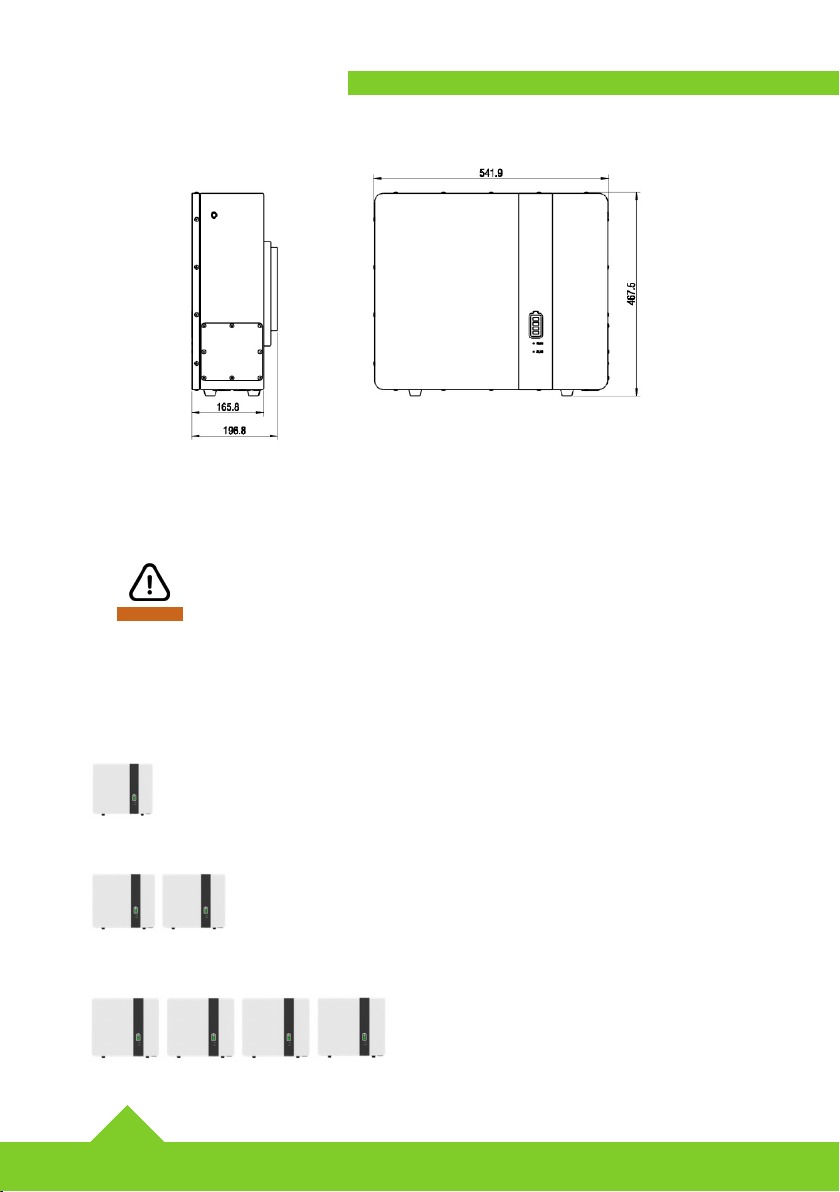
2.4 Dimensions
2.5 Capacity Options
The battery can be connected in parallel for increasing power(kW) and energy(kWh).
WARNING
»The maximum power (kW) is limited by the main cables from master battery to
inverter.
»Maximum number of batteries that can communicate in parallel is 4.
FOR EXAMPLE - One Pack is 5.12kWh
Two packs - 10.24kWh
Four packs - 20.48kWh
11
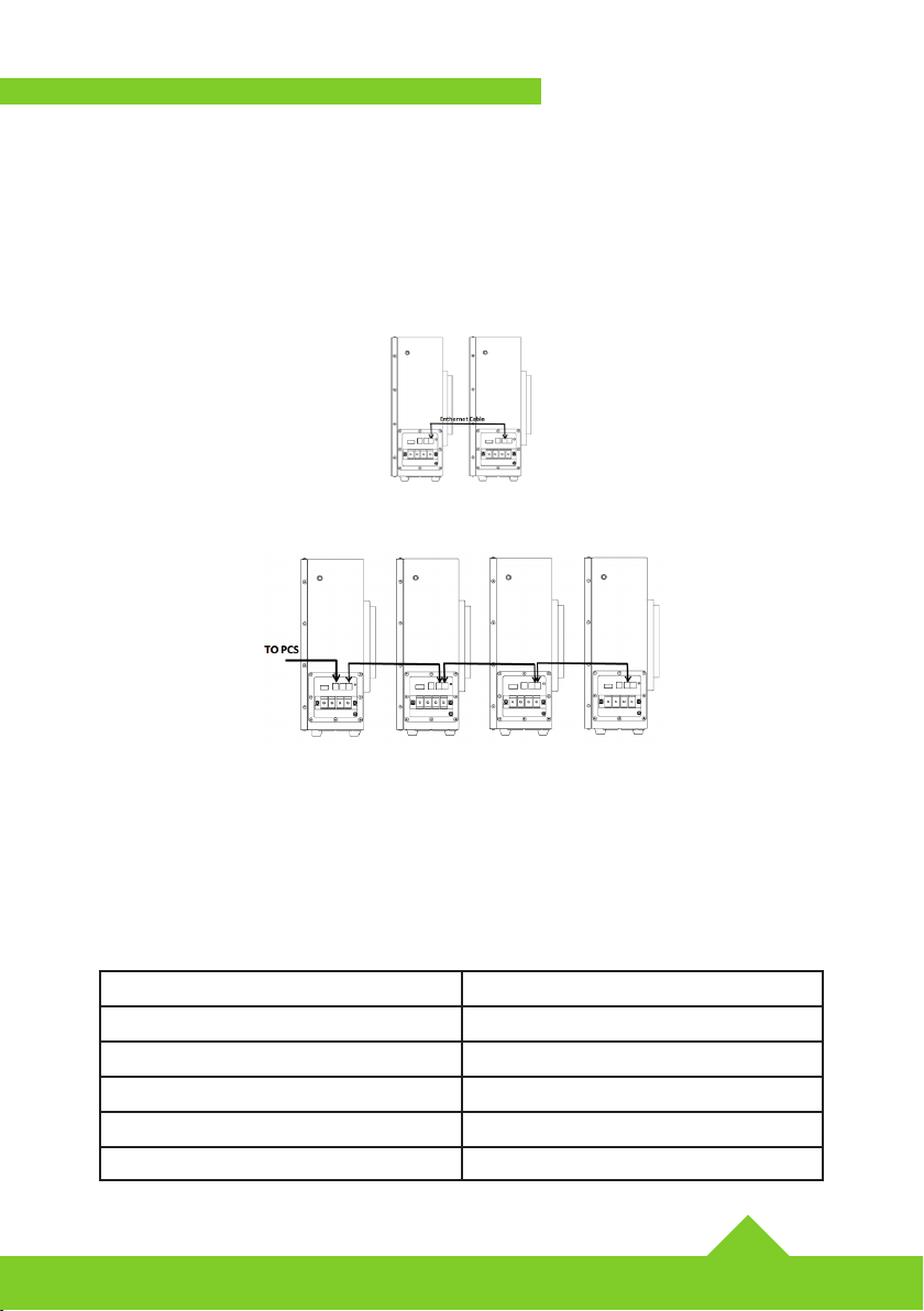
2.6 Parallel Communication
When multiple battery packs are connected in parallel, the RS485 interface is used
as the parallel communication interface. The master battery can manage all of the
paralleled slave batteries through the RS485 communication.
Two batteries RS485 parallel connection 1:
More than two batteries RS485 parallel connection 2:
2.7 Recommended Settings
Lithium batteries function differently to lead-acid batteries, therefore the device
in which you connect to the battery for charging and discharging, such as an
inverter, MPPT charger controller or UPS should implement the recommended
settings below.
Setting BPE-LFP-5.12-WM
Max. Charging Voltage 58.4V
Floating Charging Voltage 58.4V
Max. Charging Current 90A+10A*N
Max. Discharging Current 65A+10A*N
Cut-off Voltage 45V

12
3 - ATTENTIONS
»Before using the battery pack, please read the manual carefully to understand the usage and precautions;
»Non-professionals shall not disassemble the battery without authorisation;
»During usage or storage, if you notice any abnormal temperature, discoloration, deformation or other
abnormalities in the battery, please stop using the battery;
»The working temperature of the battery is -10~55°C;
»The storage temperature of the battery is -10~35°C. Please place the battery in a dry and cool environment
»If the battery is not to be used for a long period, the battery pack needs to be charged to more than 80%,
turn off the power switch, and store it in a ventilated and dry environment.
4 - SPECIFICATIONS
Model BPE-LFP-5.12-WM
Usable Capacity 5.12kWh
Voltage 51.2V
Charge Voltage 58.4V
Discharge Voltage Range 45 - 58.4V
Max. Charging Current 100
Rated Charging Current 90
Max. Discharging Current 100
Rated Discharging Current 90
Max. Output Power 5000W
Rated Output Power 4350W
DOD 85%
Modules Connection 1-4 in parallel
Communication CAN or RS485
Cycle Life > 6000
Working Temp. Range Charge: 0°C to +55°C Discharge: -10°C to +55°C
Storage Temperature -10°C - +35°C
Net Weight (kg) 52kg
Gross Weight (kg) 55kg
Product Dimension (mm) 542 x 468 x 197mm
Package Dimension (mm) 595 x 522 x 252mm

4.1 - Packing list
No. Item Description Quantity
1 Battery Pack 5.12kWh Battery pack 1
2 Power Cables 2m Power cables to Inverter 2
3 Earth Cable Earth cable 1
4 Comms Cable 2m Ethernet cable 1
5Wall Bracket Wall Bracket and fixings 1
6Paralle Cables Included 2

Badger Power Electronics
Manchester Science Park
Enterprise House
Lloyd Street N
Manchester
M15 6SE
United Kingdom
Tel: +44 (0) 161 771 2377
www.BadgerPowerElectronics.com
Table of contents
Other BPE Camera Accessories manuals


