manuals.online logo
Brands
  1. Home
  2. •
  3. Brands
  4. •
  5. Manfrotto
  6. •
  7. Camera Accessories
  8. •
  9. Manfrotto 625 User manual

Manfrotto 625 User manual

J
E
I
INTRODUCCION
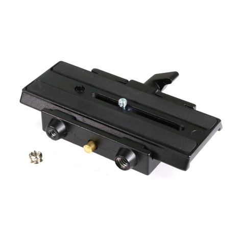
Adaptador diseñado para convertir la rótula de cualquier marca en receptiva
para el plato rápido hexagonal Manfrotto.
MONTAR EL PLATO
Monte el plato sobre la rótula (o trípode) utilizando la correspondiente rosca
hembra (1/4" o 3/8") al fondo de la base "A". Si fuera necesario, quite el
adaptador 1/4" colocado en la rosca hembra de 3/8".
Nota
El adaptador tiene también dos orificios de rosca M6 que permiten la
adaptación a cualquier soporte.
RETIRAR EL PLATO RAPIDO DEL ADAPTADOR
Para retirar el plato "G" es necesario girar la palanca de seguridad "I"
totalmente en dirección de la flecha junto con la palanca "H" hasta que el
gancho "L" se abra y suelte el plato.
(Para accionar la palanca "H" del todo el segundo pestillo de seguridad "I" ha
de ser accionado al mismo tiempo como se indica).
CAMBIO DEL TORNILLO DE LA CAMARA Y
El plato "G" se suministra con un tornillo "M" de 1/4"
Si su cámara tiene un tornillo de 3/8"
- quite el anillo "N" del plato con un destornillador
- Desenrosque el tornillo 3/8" "P" (fig. 1) del lado de la rótula
- Sustituya el tornillo de 1/4" "M" por el "P" de 3/8"
ACOPLAR EL PLATO A LA CAMARA
Fije el plato "G" enroscando el tornillo "M" que lleva en la rosca de la cámara
SIN EMPLEAR FUERZA (recuerde que ha de desenroscar primero el anillode
bloqueo "Q" por completo).
Antes del bloqueo total alinee la lente de la cámara con uno de los vertices "R"
del plato hexagonal "G".
Asegure la cámara totalmente girando el anillo "Q" contra el plato "G" (por ej.
con un destornillador).
El anillo de bloqueo "Q" está equipado con ranura "S" que facilita apretarlo.
MONTAR LA CAMARA SOBRE EL ADAPTADOR Y
Inserte el plato "G" (fig. 5) en los lados de cola de milano "T", arriba en
adaptador y luego presione el plato "G" hacia abajo hasta que la palanca
de bloqueo "H" encaje y cierre.
Cerciórese que el plato "G" (fig. 6) esté plenamente bloqueado
empujando la palanca "H" toda atras a lado de la isquierda y compruebe
que la cámara esté firmemente cogida
RETIRAR LA CAMARA
Siempre que la cámara ha de quitar se de la rótula, coja la cámara segura
con una mano mientras que maneje la palanca de bloqueo "H" y la de
seguridad "I" con la otra.
NOTA
El adaptador se suministra con dos niveles de burbuja: "M" para la
posicion horizontal, "N" para la posicion vertical.
INTRODUZIONE
Questo adattatore permette di montare il sistema rapido esagonale Manfrotto
su qualsiasi tipo di testa o morsetto.
MONTAGGIO DELL'ADATTATORE SULLA TESTA
Montare la piastra sulla testa (o sul treppiede) utilizzando, secondo il tipo di vite
d'attacco della testa, il foro filettato (da 3/8" W o 1/4"W) ricavato sul fondo del
supporto di base "A".
Rimuovere se necessario l'adattatore da 1/4"W avvitato nel foro da 3/8".
NOTA
L’adattatore è inoltre provvisto di due fori filettati da M6 per il fissaggio su
qualsiasi attrezzatura di supporto.
SMONTAGGIO DELLA PIASTRA DALL’ADATTATORE
Per rimuovere la piastra “G” (fig. 2) è necessario agire sulla leva di bloccaggio “H”.
La rotazione della leva “H” è impedita, contro sganci accidentali, dalla
sicurezza “I”.
Per la rimozione della piastra “G” si deve quindi ruotare completamente la
sicurezza “I” nel senso della freccia assieme alla leva “H”, fino allo scatto del
piolo “L”.
SOSTITUZIONE DELLA VITE D’ATTACCO DELLA PIASTRA E
La piastra “G” (fig. 3) è fornita con la vite d’attacco “M” da 1/4”.
Se la vostra fotocamera è provvista d’attacco da 3/8”:
- Togliere l’anello d’arresto “N” dalla piastra con un cacciavite
- Svitare la vite “P” da 3/8” (fig. 1) dal corpo centrale della testa
- Sostituire la vite “M” da 1/4” con la vite “P” da 3/8”.
MONTAGGIO DELLA FOTOCAMERA SULLA PIASTRA
Per fissare la fotocamera alla piastra “G” (fig. 4) avvitare, SENZA FORZARE, la
vite d’attacco “M” nel foro filettato della fotocamera fino a fondo del filetto
(ricordasi prima di svitare completamente la ghiera “Q”).
Prima del bloccaggio definitivo, allineare l’obiettivo della fotocamera con uno
dei vertici “R” dell’esagono della piastra “G”.
Bloccare definitivamente la fotocamera avvitando la ghiera “Q” contro la
piastra “G”.
La ghiera “Q” è provvista di sede “S” per facilitare (ad esempio con un
cacciavite) il serraggio più efficace.
MONTAGGIO DELLA FOTOCAMERA SULL’ADATTATORE E
Infilare dall’alto la piastra “G” (fig. 5) portandola in appoggio sui due lati
inclinati “T” della sede d’aggancio e quindi premere la piastra “G” verso il
basso fino allo scatto della leva di bloccaggio “H”.
Assicurarsi che il bloccaggio della piastra “G” (fig. 6) sia completo
spingendo a fondo la leva “H” e controllando che la fotocamera sia
saldamente ancorata
SMONTAGGIO DELLA FOTOCAMERA
Ogni volta che è necessario togliere la fotocamera dalla testa tenere
saldamente con una mano la fotocamera e con l’altra agire sulle leve di
bloccaggio “H” e sicurezza “I” (fig. 7).
NOTA
L'adattatore 3/8” dotato di 2 livelle a bolla : "M" per il livellamento orizzontale,
"N" per il livellamento verticale.
Cod. 625,03 - 09/04 Copyright © 2004 Manfrotto Bassano Italy
INSTRUCTIONS
625
1
2
1
4
5 6
7
8
3
1
2
1
4
5 6
7
8
3
1
2
4
7
8
1 3
5 6
GB FD
INTRODUCTION
L'adaptateur de fixation rapide est conçu pour adapteter le plateau hexagonal
Manfrotto sur tous les modèles de rotule non pourvus de plateau rapide.
MONTAGE DU PLATEAU
Montez le plateau sur la rotule (ou le trépied) en utilisant le filetage femelle
approprié (1/4" ou 3/8") situé sur la base de l'adaptateur "A".
Si nécessaire, enlever l'adaptateur 1/4" vissé dans la fixation 3/8" du plateau.
NOTE
L'adaptateur peut également être fixé sur n'importe quel autre support grâce
aux 2 filetages femelles M6.
RETIRER LE PLATEAU RAPIDE / BOITIER DE L’ADAPTATEUR
Pour retirer le plateau "G", actionnez le levier de sécurité "I" dans le sens de la
flèche avec le levier "H" jusqu'à ce que le loquet "L" fasse un petit bruit et libère
le plateau.
Pour libérer le levier “H”, la gàchette de securité “I” doít être simultanément
actionneé, comme indiqué.
REMPLACEMENT DE LA VIS SUR LE PLATEAU ET
Le plateau "G" est livré avec la vis de fixation 1/4" "M".
Si votre appareil a un filetage 3/8":
- Retirez le clip "N" du plateau avec un tournevis.
- Dévissez la vis 3/8" "P" (fig. 1) située sur le coté de la rotule.
- Remplacez la vis 1/4" "M" par la vis 3/8" "P".
FIXATION DU PLATEAU SUR L'APPAREIL
Fixez le plateau "G" en vissant la vis "M" dans le trou fileté de l'appareil SANS
FORCER (n'oubliez pas tout d'abord de dévisser complètement l'écrou "Q").
Avant de bloquer l'ensemble, aligner parfaitement l'objectif de l'appareil sur
l'angle "R" du plateau hexagonal "G".
Vissez l'écrou "Q" jusqu'à ce qu'il vienne en butée sur le plateau "G" afin
que l'appareil soit fixé en toute sécurité (avec un tournevis).
L'écrou "Q" a une fente "S" pour faciliter le serrage.
MONTAGE LE BOITIER SUR L’ADAPTATEUR ET
Insérez le plateau "G" (fig. 5) dans les queues d'aronde "T" au sommet de
la rotule et ensuite appuyez sur le plateau "G" jusqu'à ce que le levier de
blocage "H" fasse un petit bruit et se ferme.
Assurez vous que le plateau "G" (fig. 6) soit parfaitement bloqué en
poussant le levier "H" en arrière vers la gauche et vérifiez que l'appareil
soit correctement fixé sur l’adaptateur en toute sécurité.
RETIRER L'APPAREIL
Chaque fois que vous devez retirer l'appareil de la rotule, tenez votre
appareil d'une main et actionnez le levier de blocage "H" ainsi que le
levier de sécurité "I" de l'autre main.
NOTE
L'adaptateur est livré avec deux niveaux à bulle: "M" pour le réglage horizontal,
"N" pour le réglage vertical.
INTRODUCTION
Adapter plate designed to convert any model head to take the Manfrotto
Hexagonal Quick Release plate
MOUNTING THE PLATE
Mount the plate on the head (or tripod) using the appropriate female thread
(1/4” or 3/8”) on the bottom of the base “A”.
Remove if necessary the 1/4”W adapter screwed into the 3/8” female thread.
NOTE
The adapter also has two M6 threaded holes to allow it to be fitted to any
support.
RELEASING THE CAMERA MOUNTING PLATE FROM THE ADAPTER
To remove plate “G” it is necessary to rotate safety lever “I” fully in the direction
of the arrow together with lever “H” until peg “L” clicks open and releases the
plate.
(To operate lever “H” full, the secondary safety latch “I” must be operated
simultaneously as indicated.)
CHANGING PLATE CAMERA SCREW &
Plate “G” is supplied with 1/4” attachment screw “M”.
If your camera is equipped with a 3/8” screw:
- Remove grip ring “N” from the plate with a screwdriver.
- Unscrew 3/8” screw “P” (fig. 1) from the side of the head.
- Replace the 1/4” screw “M” with 3/8” screw “P”.
ATTACHING PLATE TO CAMERA
Fix the camera plate “G” by screwing home camera screw “M” into the
camera’s threaded hole WITHOUT APPLYING FORCE (remember to unscrew
locking ring “Q” completely first).
Before fully locking, align the camera lens with one of the “R” vertexes of the
hexagon camera plate “G”.
Secure the camera fully by screwing locking ring “Q” against plate “G”
(e.g. with screwdriver).
Locking ring “Q” is equipped with slot “S” to facilitate tightening.
MOUNTING THE CAMERA ON TO ADAPTER &
Insert the camera plate “G” (fig. 5) into the dovetail sides “T” and then
press plate “G” downwards until locking lever “H” clicks and closes.
Make sure that plate “G” (fig. 6) is fully locked by pushing lever “H” all the
way to the left side and checking that the camera is fitted securely
RELEASING THE CAMERA
Whenever the camera needs to be removed from the head, hold the
camera securely in one hand while operating locking lever “H” and safety
lever “I” with the other.
NOTE
The adapter is supplied with two spirit levels: “M” for horizontal position, “N” for
vertical position.
LENS
P
M6 M6
3/8” - 1/4”
L
I
G
G
H
M
N
R
T
H
G
M Q
G
S
H
G
G
L
H
I
EINFÜHRUNG
Mit dem Adapter 625 kann jeder Kamerakopf auf das Manfrotto
Schnellwechselsystem mit hexagonalen Kameraplatten umgerüstet werden.
MONTIEREN DER PLATTE
Montieren Sie die Platte auf den Neigekopf (oder auf das Stativ), indem Sie das
passende Innengewinde (1/4” oder 3/8”) an der Unterseite der Platte “A” benützen.
Entfernen Sie, wenn noetig, den 1/4 Zoll Adapter in den 3/8 Kopf abgeschraubt.
HINWEIS: Der Adapter verfügt auch über zwei M6 Gewinde, welche eine
Montage auf andere Halterungen erlaubt.
ENTFERNEN DER SCHNELLSPANN-KAMERAPLATTE VOM ADAPTER
Um die Kameraplatte “G” zu Entfernen, ist es nötig, die Sicherungstaste “I”
sowie den Hebel “H” gleichzeitig in Pfeilrichtung zu schwenken, bis der Stift
“L” nach oben schwenkt und die Kameraplatte gelöst wird. (Um den Hebel “H”
zu lösen, muss die Sicherungstaste “I” gleichzeitig bewegt werden.)
WECHSELN DER KAMERASCHRAUBE UND
Die Kameraplatte “G” wird mit einer Kameraschraube “M” geliefert. Falls Ihre
Kamera mit einem 3/8” Gewinde ausgerüstet ist (grosses Gewinde) dann
gehen Sie wie folgt vor: Entfernen Sie den Haltering “N” mit Hilfe eines
Schraubenziehers von der Platte. Drehen Sie die 3/8” Schraube “P” (fig. 1) aus
der Halterung auf der Seite des Neigekopfes. Ersetzen Sie die Schraube “M”
mit der 3/8” Schraube “P”.
BEFESTIGEN DER PLATTE AN DER KAMERA
Befestigen Sie die Kameraplatte “G” indem Sie die Schraube “M” LOCKER
UND OHNE KRAFTANWENDUNG ins Stativgewinde der Kamera schrauben.
(Beachten Sie dabei, dass die Sicherungsschraube “Q” zuerst vollständig
gelöst werden muss.)
Bevor die Platte ganz angeschraubt ist, muss sie korrekt ausgerichtet werden.
Richten Sie den Pfeil “R” auf der Unterseite der Kameraplatte zum Objektiv aus
(Objektivachse).
Befestigen Sie die Kamera, indem Sie die Sicherungsschraube “Q” gegen die
Platte “G” drehen (z.B. mit einem Schraubenzieher).
Die Sicherungsschraube “Q” ist mit einer Aussparung “S” ausgestattet,
welche es erlaubt, mit geringem Kraftaufwand eine optimale Arretierung
zu erhalten.
BEFESTIGEN DER KAMERA AUF DEM ADAPTER UND
Setzen Sie die Kameraplatte “G” in die seitlichen Halterungen “T” ein und
drücken Sie die Kamera herunter bis der Sicherungshebel “H” einklinkt
und schliesst.
Versichern Sie sich, dass die Platte “G” (fig. 6) komplett blockiert.
Drücken Sie dazu den Hebel “H” ganz nach links und kontrollieren Sie
nochmals, dass die Kamera sicher auf dem Neigekopf festklemmt.
ENTFERNEN DER KAMERA
Immer wenn Sie die Kamera von Neigekopf entfernen, müssen Sie diese
mit einer Hand sicher halten. Lösen Sie mit der anderen Hand den Hebel
“H” sowie gleichzeitig die Sicherungstaste “I”.
HINWEIS
Der Adapter wird mit zwei Nivellierlibellen ausgeliefert: “M” für die horizontale
Positionierung, “N” für die vertikale Positionierung.
11
2
2
1
1
1
2
M
N
1
2
1
4
5 6
7
8
3
1
2
1
4
5 6
7
8
3
1
2
1
4
5 6
7
8
3
1
5
6 7
2
4 8
3

Other Manfrotto Camera Accessories manuals

Manfrotto MKCOMPACTACN-BK User manual

Manfrotto

Manfrotto MKCOMPACTACN-BK User manual

Manfrotto MVHN12AH User manual

Manfrotto

Manfrotto MVHN12AH User manual

Manfrotto MH293D3-Q2 User manual

Manfrotto

Manfrotto MH293D3-Q2 User manual

Manfrotto MVR901ECEX User manual

Manfrotto

Manfrotto MVR901ECEX User manual

Manfrotto 804RC2 User manual

Manfrotto

Manfrotto 804RC2 User manual

Manfrotto 545B User manual

Manfrotto

Manfrotto 545B User manual

Manfrotto Lastolite XpoBalance User manual

Manfrotto

Manfrotto Lastolite XpoBalance User manual

Manfrotto 503HDV User manual

Manfrotto

Manfrotto 503HDV User manual

Manfrotto 523 PRO User manual

Manfrotto

Manfrotto 523 PRO User manual

Manfrotto 484 User manual

Manfrotto

Manfrotto 484 User manual

Manfrotto MT290DUA3 User manual

Manfrotto

Manfrotto MT290DUA3 User manual

Manfrotto 322RS User manual

Manfrotto

Manfrotto 322RS User manual

Manfrotto MVG220 User manual

Manfrotto

Manfrotto MVG220 User manual

Manfrotto 501HDV User manual

Manfrotto

Manfrotto 501HDV User manual

Manfrotto 405 User manual

Manfrotto

Manfrotto 405 User manual

Manfrotto 554 User manual

Manfrotto

Manfrotto 554 User manual

Manfrotto 560B User manual

Manfrotto

Manfrotto 560B User manual

Manfrotto MKCOMPACTADV-BK User manual

Manfrotto

Manfrotto MKCOMPACTADV-BK User manual

Manfrotto 678 User manual

Manfrotto

Manfrotto 678 User manual

Manfrotto Lastolite Lumen8 User instructions

Manfrotto

Manfrotto Lastolite Lumen8 User instructions

Manfrotto 055BWB User manual

Manfrotto

Manfrotto 055BWB User manual

Manfrotto 482 User manual

Manfrotto

Manfrotto 482 User manual

Manfrotto 056 User manual

Manfrotto

Manfrotto 056 User manual

Manfrotto Imagine More MKC3-H01 User manual

Manfrotto

Manfrotto Imagine More MKC3-H01 User manual

Popular Camera Accessories manuals by other brands

CamRanger CamRanger user manual

CamRanger

CamRanger CamRanger user manual

Custom Brackets HDV CAGE KIT Instructions for use

Custom Brackets

Custom Brackets HDV CAGE KIT Instructions for use

Aegis ABL052010P user manual

Aegis

Aegis ABL052010P user manual

Saft SRA Series Installation and operating instructions

Saft

Saft SRA Series Installation and operating instructions

Kodak TIB5200 technical information

Kodak

Kodak TIB5200 technical information

Videotec HEG instruction manual

Videotec

Videotec HEG instruction manual

Ikelite 6171.11 manual

Ikelite

Ikelite 6171.11 manual

Pentax Auto Bellows Slide Copier K user manual

Pentax

Pentax Auto Bellows Slide Copier K user manual

Nikon UT-1 user manual

Nikon

Nikon UT-1 user manual

dji RONIN 4D quick start guide

dji

dji RONIN 4D quick start guide

SLIK ABLE 300DX user manual

SLIK

SLIK ABLE 300DX user manual

Rebelcell 36V70 user manual

Rebelcell

Rebelcell 36V70 user manual

Trojan GC2 48V quick start guide

Trojan

Trojan GC2 48V quick start guide

Calumet 7100 Series CK7114 operating instructions

Calumet

Calumet 7100 Series CK7114 operating instructions

Ropox 4Single Series User manual and installation instructions

Ropox

Ropox 4Single Series User manual and installation instructions

Cambo Wide DS Digital Series Main operating instructions

Cambo

Cambo Wide DS Digital Series Main operating instructions

Samsung SHG-120 Specification sheet

Samsung

Samsung SHG-120 Specification sheet

Ryobi BPL-1820 Owner's operating manual

Ryobi

Ryobi BPL-1820 Owner's operating manual

manuals.online logo
manuals.online logoBrands
  • About & Mission
  • Contact us
  • Privacy Policy
  • Terms and Conditions

Copyright 2025 Manuals.Online. All Rights Reserved.