LED Wall Pack Instructions www.cooperlighting.com
IL51879322
2
THIS PRODUCT MUST BE INSTALLED IN ACCORDANCE WITH THE APPLICABLE NATIONAL ELECTRICAL CODE AND LOCAL BUILDING CODES BY A
PERSON FAMILIAR WITH THE CONSTRUCTION AND OPERATION OF THE PRODUCT AND THE HAZARDS INVOLVED.
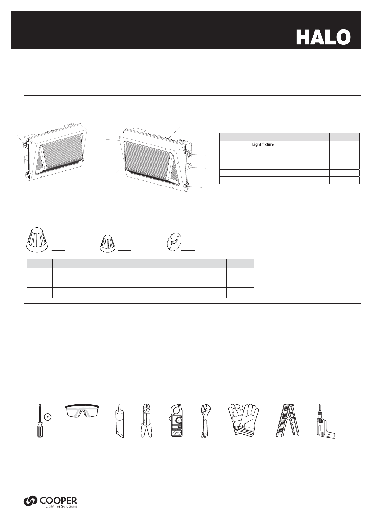
• Please read and understand this entire manual before attempting to assemble, install or operate this light fixture.
• Save these instructions and warnings
• This light fixture requires a 120-277 Volt AC power source. Any other connection voids the warranty.
• Fixture should be installed by persons with experience in household wiring or by a qualified electrician.
• This light fixture must be properly grounded.
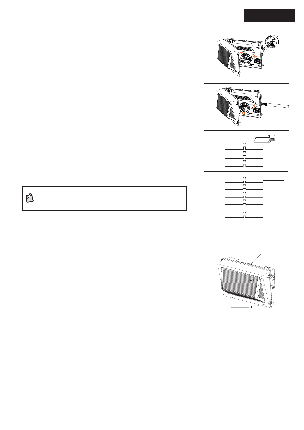
• Make sure connections are secure using wire nuts, crimp-on plugs or other UL approved connecting devices.
• This fixture should be installed outdoors to a wall or a pole.
• Disassembling your fixture will void the warranty.
• Always turn OFF the power before adjusting or servicing this light fixture, wear rubber soled shoes and use a wooden or insulated (non-grounded)
ladder.
• This product may contain chemicals known to be hazardous. Thoroughly wash hands after installing, handling, cleaning or otherwise touching the
product.
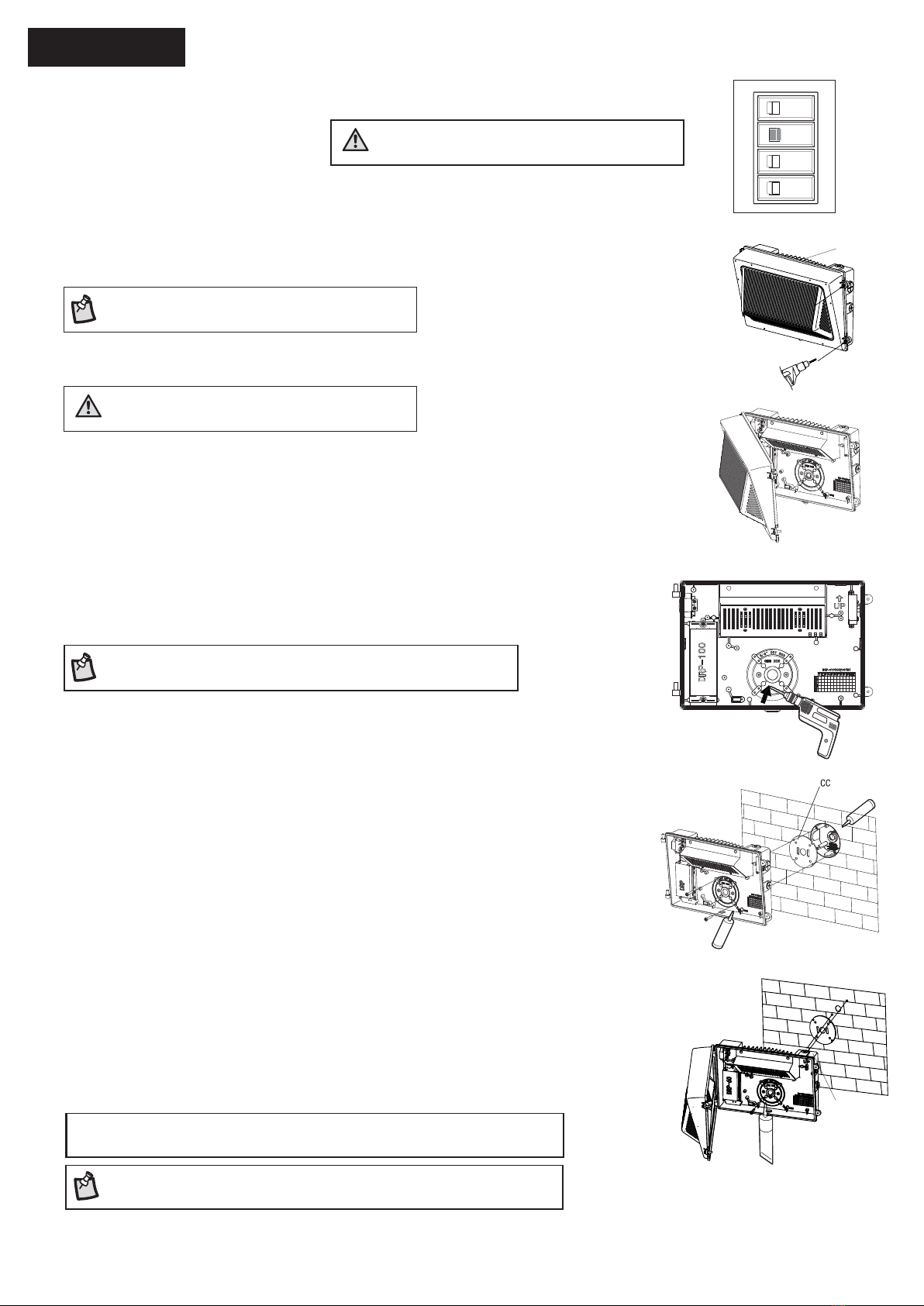
WARNING: Before
installation or servicing, turn
the power OFF at the circuit
breaker or fuse. Place tape over
the circuit breaker switch and
verify power is OFF at the light
fixture
IMPORTANT: This device complies with part 15 Class A of the FCC Rules. Operation is subject to the following two conditions: (1) This device may
not cause harmful interference, and (2) this device must accept any interference received, including interference that may cause undesired operation.
These limits are designed to provide reasonable protection against harmful interference in a residential installation. This equipment generates, uses,
and can radiate radio frequency energy and, if not installed and used in accordance with the instructions, may cause harmful interference to radio
communications. However, there is no guarantee that interference will not occur in a particular installation. If this equipment does cause harmful
interference to radio or television reception, which can be determined by turning the equipment OFF and ON, the user is encouraged to try to correct
the interference by one or more of the following measures:
•Reorient or relocate the receiving antenna.
•Increase the separation between the equipment and receiver.
•Connect the equipment into an outlet on a circuit different from that to which the receiver is connected.
•Consult the dealer or an experienced radio/TV technician for help.
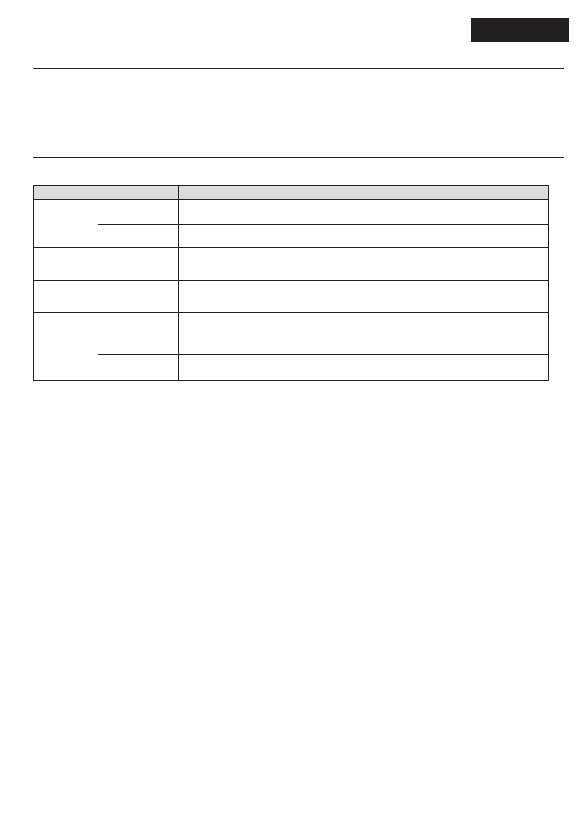
WARNING: RISK OF FIRE. Keep
the lamp heads at least 3 in. (76 mm)
from combustible materials.
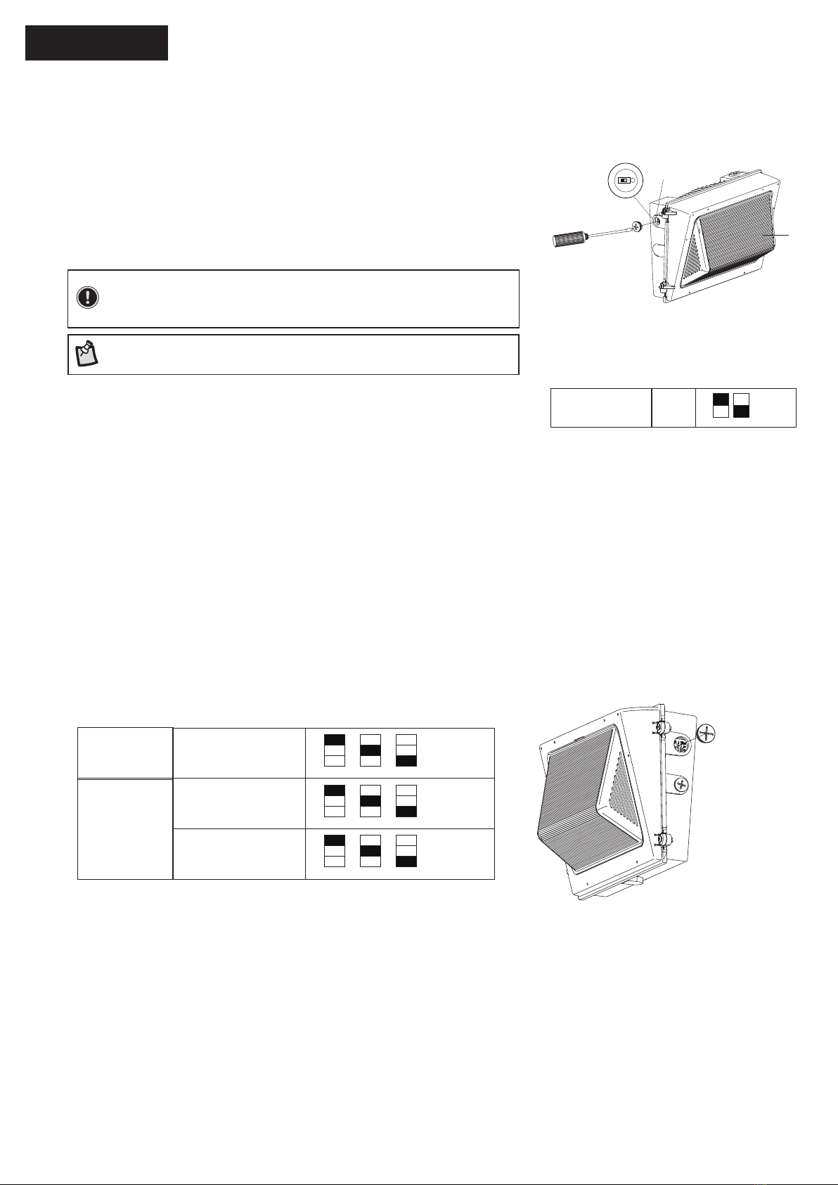
NOTICE: Do not connect this fixture to a dimmer switch unless
listed on dimmer compatibility list.
NOTICE: FCC Regulations state that any unauthorized changes
or modifications to this equipment not expressly approved by the
manufacturer could void the user’s authorization to operate this
equipment.
CAUTION: BURN HAZARD. Allow
the light fixture to cool before touching
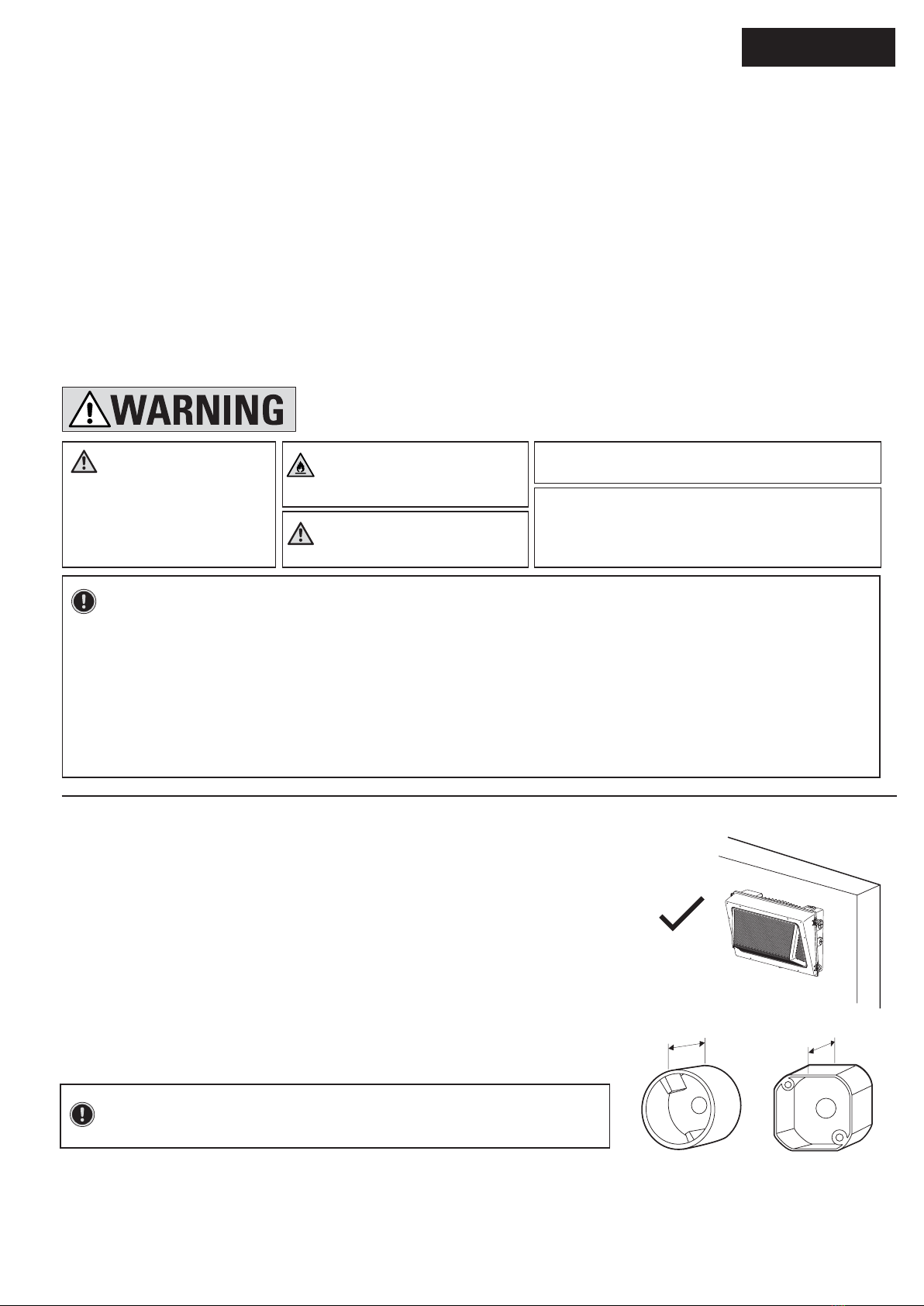
NOTE: The mounting base (D) mounts to recessed mounted standard junction boxes or to the
surface directly. Junction box must be at least 1-1/2 in. in depth for proper installation for a
recessed mount application.
IMPORTANT SAFETY INSTRUCTIONS
PREPARING FOR INSTALLATION
READ AND FOLLOW
THESE INSTRUCTIONS
1.The fixture can be mounted in the following two ways:
•Junction Box Mount: Use a junction box to mount the fixture.
•Surface Conduit Mount: The fixture can also be mounted directly on the wall surface using
conduit entry.
2.To ensure proper dusk-to-dawn operation, ensure the photocell is oriented at
the top for a wall mount installation, in an area that receives daylight. Do not
place too close to reflective surfaces.
3.When installing two fixtures on one switch,make sure the switch is rated for at
least a 1A inductive load.
4.If dimming,use with 0-10V dimming switch.
1-1/2"
Wall Mount
1-1/2"
Round Octagonal/Square