B+K precision 8600 Series Owner's manual

8600 Series Programming Manual
Models: 8600, 8601, 8602
PROGRAMMING MANUAL

Safety Summary
The following general safety precautions must be observed during all phases of operation of this
instrument. Failure to comply with these precautions or with specific warnings elsewhere in this
manual violates safety standards of design, manufacture, and intended use of the instrument. We
assume no liability for the customer’s failure to comply with these requirements.
ENVIRONMENTAL CONDITIONS
This instrument is intended for indoor use, pollution degree 2 environments. It is designed to operate
at a maximum relative humidity of 95% and at altitudes of up to 2000 meters. Refer to the
specifications tables forthe AC mains voltagerequirements and ambient operating temperature range.
BEFORE APPLYING POWER
Verifythat all safety precautions are taken. Note the instrument's external markings described under
"Safety Symbols".
GROUND THE INSTRUMENT
This product isa Safety Class 1 instrument (provided with a protectiveearth terminal).To minimize
shock hazard, the instrument chassis and covermust be connected to an electrical ground. The
instrument must be connected tothe ACmains power through agrounded power cable,withthe
ground wire firmly connected to an electrical ground (safety ground) at the power outlet. Note: Any
interruption of the protective (grounding) conductor or disconnection of the protective earth terminal
will cause a potential shock hazard that could result in personal injury.
DO NOT OPERATE IN AN EXPLOSIVE ATMOSPHERE
Do not operate the instrument in the presence of fumes or flammable gases.
KEEP AWAY FROM LIVE CIRCUITS
Operating personnelmust not remove instrument covers except as instructed in this guide for
installing or removing electronic load modules. Component replacement and internal adjustments
must be made only by qualified service personnel. Do not replace components with power cable
connected. Under certain conditions dangerous voltages may exist even with the power cable
removed. To avoid injuries, always disconnect power, discharge circuits, and remove external voltage
sources before touching components.
DO NOT SERVICE OR ADJUST ALONE
Do not try to do some internal service or adjustment unless anotherperson capable of rendering first
aid resuscitation is present.

Safety Symbols
Direct current
Alternating current
Both direct and alternating current
Protective earth (ground) terminal
Attention (refer to accompanying documents)
WARNING
The WARNING sign denotes a hazard. It calls attention to a procedure, practice, or the like, which,
if not correctlyperformed or adhered to, could result in personal injury. Do not proceed beyond a
WARNING sign until the indicated conditions are fully understood and met.
CAUTION
The CAUTION sign denotes a hazard. It calls attention to an operating procedure, or the like, which,
if not correctly performed or adhered to, could result in damage to or destruction of part or all of
the product. Do not proceed beyond a CAUTION sign until the indicated conditions are fully
understood and met.

Table of Contents
Safety Summary.........................................................................................2
Table of Contents.......................................................................................4
Chapter 1...................................................................................................5
Introduction to Programming.....................................................................5
1.1 GPIB Capabilities of the Electronic Load...........................................................................................5
1.2 RS-232 Capabilities of the Electronic Load.......................................................................................6
1.3 USB-TMC Capabilities of the Electronic Load...................................................................................8
1.4 Programming the Status Registers ...................................................................................................8
Chapter 2.................................................................................................17
Introduction to SCPI.................................................................................17
2.1 Types of SCPI Commands................................................................................................................17
2.2 Types of SCPI Messages..................................................................................................................20
2.3 SCPI Data Formats...........................................................................................................................22
2.4 SCPI Command Completion............................................................................................................24
Chapter 3.................................................................................................26
SCPI Commands .......................................................................................26
3.1 Language Dictionary........................................................................................................................26
3.2 Common Commands ......................................................................................................................27
3.3 Subsystem Commands....................................................................................................................34
Trigger Commands............................................................................................................................34
System Commands............................................................................................................................35
Trace Commands..............................................................................................................................40
Source Commands............................................................................................................................43
List Commands..................................................................................................................................60
Measurement Commands................................................................................................................63
3.4 SCPI Command Tree........................................................................................................................65
Chapter 4.................................................................................................73
Programming Examples............................................................................73
4.1 Introduction.................................................................................................................................... 73
4.2 Programming the Input...................................................................................................................73
4.3 Programming Lists...........................................................................................................................76
Chapter 5.................................................................................................77
Error Messages ........................................................................................77

5
Chapter 1
Introduction to Programming
This guide contains programming information forthe B&K Precision 8600 series DCelectronic load.
Unless otherwise noted, this documentwill referto allof these instruments as “electronic load”.
1.1 GPIB Capabilities of the Electronic Load
All electronic load functions except for setting the communication parameters are programmable over
the GPIB. The IEEE 488.2 capabilities of the electronic load are described in the table below.
GPIB Capabilities
Response
Interface
Function
Talker/Listener
All electronic load functions except for setting the communication
parameters are programmable over the GPIB. The electronic load can
send and receive messages over the GPIB. Status information is sent
using a serial poll.
AH1, SH1,
T6, L4
Service Request The electronic load sets the SRQ line true if there is an enabled service
request condition. SR1
Remote/Local
In local mode,theelectronic load is controlled from the front panel but
will also execute commands sent overthe GPIB. The electronic load
powersup in local modeand remains in local mode until it receives a
command over the GPIB. Once the electronic load is in remote mode,
the front panel REM annunciator turns on, all front panel keys (except
Shift + Local)are disabled, and the display is in normal metering mode.
Pressing Shift + Local on the front panel returns the electronic load to
local mode. This can be disabled using local lockout so that only the
controller or the power switch can return the electronic load to local
mode.
RL1
Device Trigger The electronic load willrespond tothe device trigger function. DT1
Group Execute
Trigger
The electronic load will respond to the group execute trigger function. GET
Device Clear
The electronic load responds to the Device Clear(DCL) and
Selected Device Clear (SDC) interface commands. They cause the
electronic load to clear any activitythat would prevent it from
receiving and executing a new command (including *WAI and
*OPC?). DCL and SDC do not change any programmed settings.
DCL,SDC

6
GPIB Address
The electronic load operates from a GPIB address that is set from the front panel. To set the GPIB
address, press Shift + ⑦(System menu) on the front panel and enter the addressusingthe Entry keys.
The address can be set from 0 to 30.The GPIB address is stored in non-volatile memory.
1.2 RS-232 Capabilities of the Electronic Load
Use a cable with two serial interfaces (DB9) to connect the electronic load and PC. It can be activated
by selecting <RS-232> in <Communication> of the System menu (Shift + 8 on the front panel). NOTE:
There are two serial interfaces on the rear panel: the top 9-pin COM (female) interface is the RS-232
communication interface and the bottom 9-pin COM (male) serial port connection is not for use. All
SCPI commands are available through RS-232 programming. The EIA RS-232 standard defines the
interconnections between data terminal equipment (DTE) and data communications equipment (DCE).
The electronic load is designed to be a DTE and can be connected to another DTE such as a PC COM
port through a null modem cable.
NOTE: The RS-
232 settings in your program must match the settings specified in the front panel System
menu. Press Shift + 8 on the front panel to enter the System menu if you need to change the settings.
You can break data transmissions by sending a ^C or ^X character string to the electronic load. This
clears any pending operation and discards any pending output.
RS-232 Data Format
The RS-232 data is a 10-bit word with one start bit and one stop bit.
The number of start and stop bits are not programmable. However, the following parameters are
selectable in the System menu using the front panel Shift + 8 key.
Baud Rate
The System menu (Shift+ 8) lets you select one of the following baud rates, which are stored in non-
volatile memory: 4800, 9600, 19200, 38400, 57600, or 115200.
Parity=None Start Bit 8 Data Bits Stop Bit

7
Parity
None - eight data bits without parity
Even - seven data bitswith even parity
Odd -seven databits with odd parity
RS-232 Flow Control
The RS-232 interface supports the following flow control options. For each case, the electronic load will
send a maximum of five characters after hold-off is asserted by the controller. The electronic load is
capable of receiving as many as fifteen additional characters after it asserts hold-off.
•The electronic load asserts its Request to Send (RTS) line to signal hold-off when its input buffer
is almost full, and it interprets its Clear to Send (CTS) line as a hold-off signal from the
controller.
•When the input queue of the electronic load becomes more than ¾ full,the instrument issues
an X-OFF command. The control program should respond to this and stop sending characters
until the electronic load issues the X-ON, which it will do once its input buffer has dropped
below half-full. The electronic load recognizes X_ON and X_OFF sent from the controller. An X-
OFF will cause theelectronic load to stop outputting charactersuntil it sees an X-ON.
•NONE: There is no flow control.
Flow control options are stored in non-volatile memory.
RS-232 Connections
The RS-232 serial port can be connected to the serial port of a controller (i.e., personal computer)using
a null modem RS-232 cable terminated with DB-9 connectors. Figure 1 shows the pinout for the
connector.
If your computer uses a DB-25 connector for theRS-232 interface, you will need a cable or adapter
with a DB-25 connector on one end and a DB-9 connector on the other. It must be a straight-through
(not null modem) cable.
Figure 1 - RS-232 Connector Pinout
Pin Signal Description
1
NC
No Connection
2
TXD
Transmit Data
3 RXD Receive Data

8
4
NC
No Connection
5
GND
Ground
6
NC
No Connection
7
CTS
Clear to Send
8
RTS
Ready to Send
9
NC
No Connection
RS-232 Troubleshooting
If you are having trouble communicating over the RS-232 interface, check the following:
•The computer and the electronic load must be configured for the same baud rate, parity,
numberof data bits, and flow control options. Note that the electronic load is configured for 1
start bit and 1 stop bit (these values are fixed).
•The correct interface cables or adapters must be used, as described under the RS-232
connector. Note that even if the cable has the proper connectors for your system, the internal
wiring may be incorrect.
•The interface cable must be connected to the correct serial port on your computer (COM1,
COM2, etc.) and the correct 9-pin serial port on the mainframe.
1.3 USB-TMC Capabilities of the Electronic Load
All electronic load functions are programmable over the USB.
The USB488 interface capabilities of the electronic load are described below:
•The interface is IEEE 488.2 standard USB488 interface.
•The interface accepts REN_CONTROL, GO_TO_LOCAL, and LOCAL_LOCKOUT requests.
•The interface accepts MsgID = TRIGGERUSBTMC command message and forwards TRIGGER
requests to the function layer.
The USB488 device capabilities of the electronic load aredescribed below:
•The device understands all mandatory SCPI commands.
•The device is SR1 capable.
•The device is RL1 capable.
•The device is DT1 capable.
1.4 Programming the Status Registers
You can use status register programming to determine the operating condition of the electronic load at
any time. Forexample, you may program the electronic load to generate an interrupt (assert SRQ)

9
when an event such as a current protection occurs. When the interrupt occurs, your program can then
act on the event in the appropriate fashion.
The following table defines the status bits. Figure shows the status register structure of the electronic
load. The Standard Event, Status Byte, and Service Request Enable registers and the Output Queue
perform standard GPIB functions as defined in the IEEE 488.2 Standard Digital Interface for
Programmable Instrumentation. The Operation Status and Questionable Status registers implement
functions that are specific to the electronic load.
Bit Configurations of Status Registers Operation Status Group
Bit Signal Meaning
0 CAL Calibrating. The electronic load is computing new calibration constants.
5 TRG Waiting. The electronic load is waiting for a trigger.
Status Group
Bit Signal Meaning
0 VF Voltage Fault. Either an overvoltage or a reverse voltagehas occurred. This bit
reflects the active state of the FLT pin on theback of the unit.The bit remains
set until the condition is removedand PROT:CLE is programmed.
1 OC
Overcurrent. An overcurrent condition has occurred. This occurs if the current
exceeds 102% of the rated current or if it exceeds the user-programmed
current protection level.Removing the overcurrent condition clearsthe bit. If
the condition persists beyond the user programmable delay time, PS bit is also
set and the input is turned off. Both bits remain set untilthe condition is
removed and PROT:CLE is programmed.
2 RS Remote Sense. When the remote sense is connected, this bit is set.
3 OP
Overpower. An overpower condition has occurred. This occurs if the unit
exceeds the max power or it exceeds the user-programmed power protection
level. Removing the overpower condition clears the bit. If the condition
persists beyond the user programmable delay time, PS bit is also set and the
input is turned off.Bothbits remain set until the condition is removed and
PROT:CLE is programmed.

10
4 OT Overtemperature. An overtemperature condition has occurred. Both this bit
and PS bit are set and the input is turned off. Both bits remain set until
the unit
is cooled down and PROT:CLE is programmed.
7 RUN List run or stop status. When list is running, this bit is set.
8 EPU Extended Power Unavailable. This bit isnot used.
9 RRV
Remote Reverse Voltage. A reverse voltage condition has occurred on the
senseterminals.Both thisbit and VF bit areset. Removing the reverse voltage
clears this bit but does not clear VF bit. VF bit remains set until PROT:CLE is
programmed.
10 UNR Unregulated. The input is unregulated. When the input is regulated this bit is
cleared.
11 LRV
Local Reverse Voltage. A reverse voltage condition has occurred on the input
terminals. Both this bit and VF bit are set. Removing the reverse voltage clears
this bit but does not clear PS bit. PS bit remains set until PROT:CLE is
programmed.
12 OV Overvoltage. An overvoltage condition has occurred. Both this bit and VF bit 0
are set and the electronic loads are turned off. Both bits remain set until the
condition is removed and PROT:CLE is programmed.
13 PS Protection Shutdown. The protection shutdown circuit hastripped because of
an overcurrent, overpower, or overtemperature condition
. The bit remains set
until PROT:CLE is programmed.
14 VON Voltage of sink current on. When the voltage of input exceeds the user-
programmed Von level, this bit is set.
15 TBF Trace Buffer Full.
Questionable Status Group
Standard Event Status Group
Bit Signal Meaning

11
0 OPC
Operation Complete.
The loadhas completed all pending operations. *OPC
must be programmed for this bit to be set when pending operations are
complete.
2 QYE Query Error.
The output queue was read with no data present or the data was
lost. Errorsin the rangeof 499through 400 can set this bit.
3 DDE Device-Dependent Error. Memory was lost or self-test failed. Errors in the
range of 399 through 300 can set this bit.
4 EXE
Execution Error. A command parameter was outside its legal range,
inconsistent with the load's operation, or prevented from executingbecause
of an operating condition. Errorsin the range of299through 200 can setthis
bit.
5 CME
Command Error. A syntax or semantic error has occurred or the load received
a <get> within a program message.Errors in the range of 199 through 100 can
set this bit.
7 PON Power-On. The unit has been turned off andthen on since this bit waslast
read.
Status Byte and Service Request Enable Registers
Bit Signal Meaning
2 EAV Error Available Summary. Indicates if the Error Queue contains data.
3 QUES Questionable Status Summary. Indicates if an enabled questionable event has
occurred.
4 MAV Message Available Summary. Indicates if the Output Queue contains data.
5 ESB Event Status Summary. Indicates if an enabled standard event has occurred.
6 RQS/MSS
Request Service. During a serial poll, RQS is returned and cleared.
Master Status Summary. For an *STB?query, MSS is returned without being
cleared.
7 OPER Operation Status Summary. Indicates if an operation event has occurred.

12
Figure 2 - Load Status Register Structure

13
Condition registers
All status register sets have a condition register. A condition register is a real-time, read-only register
that constantly updates to reflect the current operating conditions of the instrument.
Use the :CONDition?query commands in the STATus Subsystem toread the condition registers. See
Chapter 3 for more information.
Event registers
Each status register set has an event register. An event register is a latched, read-only register whose
bits are set by the corresponding condition register. Once a bit in an event register is set, it remains set
(latched) until the register is cleared by a specific clearing operation. The bits of an event register are
logically ANDed with the bits of the corresponding enable registerand applied to an OR gate. The
output of the OR gate is appliedto the Status Byte Register.
Use the *ESR? Common Command to read the Standard Event Register. All other event registers are
read using the :EVENt? query commands in the STATus Subsystem. See Chapter 3 for more
information.
An event register is cleared when it is read.The following operations clear all event registers:
•Cycling power
•Sending *CLS
Enable registers
Each status register set has an enable register. An enable register is programmed by you and serves as
a mask for the corresponding event register. An event bit is masked when the corresponding bit in the
enable register is cleared (0). When masked, a set bit in an event register cannot set a bit in the Status
Byte Register (1 AND 0 = 0). To use the Status Byte Register to detect events (i.e., serial poll), you must
unmask the events by setting (1) the appropriatebits of the enable registers. To program and query
the Standard Event Status Register,use the *ESE and *ESE?Common Commandsrespectively. All other
enable registers are programmed and queried using the :ENABle and :ENABLe? commands in the
STATus Subsystem. See Chapter 3 for more information.
An enable register is not cleared when it isread. Thefollowing operations affect theenable registers:
•Cycling power clears all enable registers
•:STATus:PREset clearsthe following enable registers:
oOperation Event EnableRegister
oQuestionable Event Enable Register
•*ESE 0 clearsthe Standard Event Status Enable Register.
Output queue
The output queue holdsdata that pertains to the normaloperation of the instrument. For example,
when a query commandis sent,the response message is placed on the output queue.

14
When data is placed in the output queue, the Message Available(MAV) bit in the Status Byte Register
gets set. A data message is cleared from the output queue when it is read.The output queue is
considered cleared when it is empty. An empty output queue clearsthe MAV bit in the Status Byte
Register.
Error queue
The error queue holds error and status messages. When an error or statusevent occurs, a message
that definestheerror/statusis placed in the error queue. This queuewill hold up to 10 messages.
When a message is placed in the error queue, the Error Available (EAV) bit in the Status Byte Register is
set. An error message is cleared from the Error/Status queue when it is read. The errorqueue is
considered cleared when it is empty. An empty error queue clears the EAV bit inthe Status Byte
Register. Read an error message from the error queue by sending the following SCPI query command:
:SYSTem:ERRor?
Status Byte and Service Request (SRQ)
Service request is controlled by two 8-bit registers: the Status Byte Register and the Service Request
Enable Register.
Status Byte Register
The summary messages from the status registersand queues areused to set orclear the appropriate
bits (B0, B2, B3, B4, B5, and B7) of the Status Byte Register. These bits do not latch, and their states (0
or 1) are solely dependent on the summary messages (0 or 1). For example, if the Standard Event
Status Register is read,its register will clear. Asa result, its summary message will reset to 0, which in
turn will clear the ESB bit in the Status Byte Register.
Bit B6 in the Status Byte Register is either:
•The Master Summary Status (MSS) bit, sent in response to the *STB? Command, indicates the
status of any set bits with corresponding enable bits set.
•The Request forService (RQS) bit, sent in response to a serial poll, indicates which device was
requesting service by pulling on the SRQ line.
For a description of the other bits in the Status Byte Register, see “Common commands, *STB?” The
IEEE-488.2 standard uses the following common query command to read the Status Byte Register:
*STB?
When reading the Status Byte Register using the *STB? command, bit B6is called the MSSbit. None of
the bits in the Status Byte Register are cleared when using the *STB? command to read it.
The IEEE-488.1 standard has a serial poll sequence that also reads the Status Byte Register and is better
suited to detect a service request (SRQ). When using the serial poll, bit B6 is called the RQS bit. Serial
polling causes bit B6 (RQS) to reset. Serial polling is discussed in more detail later in this section
entitled “Serial Poll and SRQ.” Any of the following operations clear all bits of the Status Byte Register:

15
•Cycling power
•Sending the *CLS common command
Note: The MAV bit may or may not be cleared.
Service request enable register
This register is programmed by you and serves as a mask for the Status SummaryMessage bits (B0, B2,
B3, B4, B5, and B7) of the Status Byte Register. When masked, a set summary bit in the Status Byte
Register cannot set bit B6(MSS/RQS) of theStatus Byte Register.Conversely, when unmasked, a set
summary bit in the Status Byte Registersetsbit B6.
A Status SummaryMessage bit in the Status Byte Registeris maskedwhen the corresponding bitin the
Service Request Enable Register is cleared (0). When the masked summary bit in the Status Byte
Register sets, it is ANDed with the corresponding cleared bit in the Service Request Enable Register.
The logic “1” output of the AND gate is applied to the input of the OR gate and,thus, sets the MSS/RQS
bit in the StatusByte Register. The individualbitsof theService Request EnableRegister can be set or
cleared by using the following common command:
*SRE <NRf>
To read the Service Request Enable Register, use the *SRE? query command. The Service Request
Enable Register clears when power is cycled or a parameter (n) value of zero is sent with the *SRE
command (*SRE 0).
Serial poll and SRQ
Any enabled event summary bit that goes from 0 to 1 will set RQS and generate a service request
(SRQ). In your test program, you can periodicallyread the Status Byte Register to check if a service
request (SRQ) has occurred and what caused it. If an SRQ occurs,the program can, forexample,branch
to an appropriate subroutine that will service therequest. Typically,service requests (SRQs) are
managed by the serial poll sequence of the electronic load. If an SRQ does not occur, bit B6 (RQS) of
the Status Byte Register will remain cleared and the program will simply proceed normally after the
serial poll is performed. If an SRQ does occur, bit B6 of the Status Byte Register will set and the
program can branch to a service subroutine when the SRQ is detected by the serial poll. The serial poll
automatically resets RQSof the Status Byte Register. This allows subsequent serial pollsto monitor bit
B6 for an SRQ occurrence generated by other event types. After a serial poll, the same event can cause
anotherSRQ, even if the event register that caused the first SRQ has not been cleared.
A serial poll clears RQS but does not clear MSS. The MSS bit stays set until all Status Byte event
summary bits are cleared.

16
Trigger model operation
Once the instrument is taken out of idle, operation proceeds through the trigger model down to the
device action.
Control Source — As shown in Figure 3, a controlsource is used to hold up operation untilthe
programmed event occurs. The control source options are explained as follows:
•HOLD — Only the TRIG:IMM command will generate a trigger in HOLD mode. All other trigger
commands are ignored.
•MANual — Event detection is satisfied bypressing the TRIG key.
•TIMer — This generates triggers that are in synchronization with the electronic load's internal
oscillator as the trigger source. The internal oscillatorbegins running as soon as this command
is executed. Use TRIG:TIM to program the oscillator period.
•EXTernal — Event detection is satisfied when an input trigger via the TRIGGER LINK connector is
received by the electronic load.
•BUS — Event detection is satisfied when a bus trigger (GET or *TRG) is received by the
electronic load.
Delay — A programmable delay is available after the event detection. The delay can be manually set
from 0 to 999999.999 seconds.

17
Chapter 2
Introduction to SCPI
SCPI (Standard Commands for Programmable Instruments) is aprogramming language for controlling
instrument functions over GPIB, RS-232, USB, and Ethernet interface. SCPI is layered on top of the
hardware portion of IEEE488.2. The sameSCPI commands and parameters control the same functions
in different classes of instruments.
Conventions Used in This Guide
Angle brackets < > Items within angle brackets are parameter abbreviations. For example,
<NR1> indicates a specific form of numerical data.
Vertical bar | Vertical bars separate alternative parameters. For example, NORM | TEXT
indicates that either "NORM" or "TEXT" can beused as a parameter.
Square Brackets [ ] Items within square brackets are optional. The representation [SOURce:]
VOLTage means that SOURce: may be omitted.
Braces { } Braces indicate parameters that may be repeated zero or moretimes. It is
used especiallyfor showing arrays. The notation <A>{<,B>} shows that
parameter "A" must be entered, while parameter"B" may be omitted or may
be entered one or more times.
2.1 Types of SCPI Commands
SCPIhas two types of commands, common and subsystem.
Common:
Common commands generally are not related to specific operation but to controlling overall
electronic load functions, such asreset, status,and synchronization. Allcommon commands
consist of athree-letter mnemonic preceded by an asterisk (ex:*RST, *IDN?, *SRE 8).
Subsystem:
Subsystem commandsperform specific electronic loadfunctions. They are organized intoan
inverted tree structure with the "root" at the top. The following figure shows a portion of a
subsystem command tree, from which you access the commands located along the various paths.
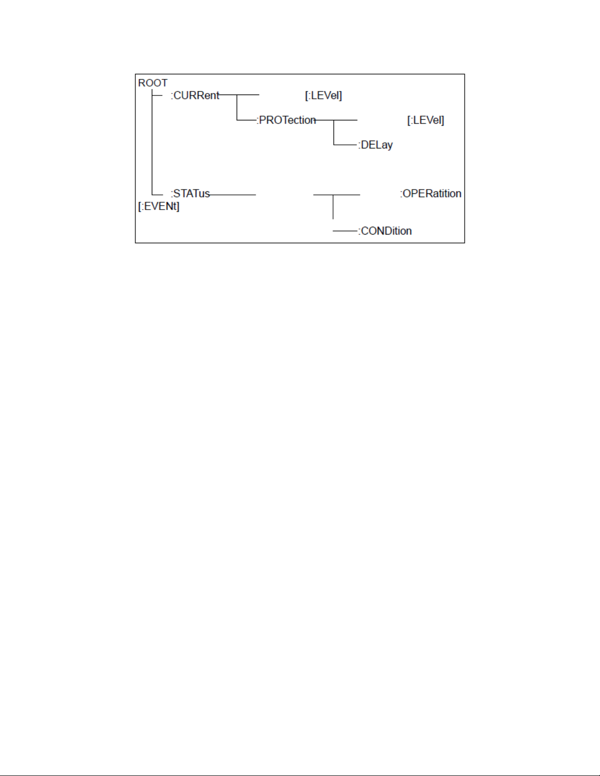
18
Figure 4 - Partial Command Tree
Multiple Commands in a Message
Multiple SCPI commands can be combined and sent as a single message with one message terminator.
There are two important considerations when sending several commands within a single message:
•Use a semicolonto separate commandswithin amessage.
•There is an implied header path that affects howcommands are interpreted by the
electronic load.
The header path can be thought of as a string that gets inserted before each command within a
message. For the first command in a message, the header path is a null string. Foreach subsequent
command the header path is defined as the characters that make up theheaders of the previous
command in themessage up to and including the last colon separator. An exampleof a messagewith
two commands is:
CURR:LEV 3;PROT:STAT OFF
which shows the use of the semicolon separating the two commands, and also illustrates the header
path concept.Notethat with the second command,the leading header "CURR" wasomitted because
after the "CURR:LEV3" command, the header path became defined as "CURR" andthus the instrument
interpreted the second command as:
CURR:PROT:STAT OFF
In fact,itwould have been syntactically incorrect toinclude the "CURR" explicitly in the second
command, since the result after combining it with the header path would be:
CURR:CURR:PROT:STAT OFF
which is incorrect.

19
Moving Among Subsystems
In order to combine commands fromdifferent subsystems, you needto be able to resetthe header
path to a null string within a message.You dothisby beginning the command with a colon (:), which
discards any previous header path. For example, you could clear the output protection and check the
status of the Operation Condition register in one message by using a root specifier as follows:
PROTection:CLEAr; :STATus:OPERation:CONDition?
The following message shows how to combine commands from different subsystems as well as within
the same subsystem:
POWer:LEVel 200; PROTection 28; : CURRent: LEVel 3; PROTection:STATe ON
Observe the use of the optional header LEVel to maintain the correct path within the voltage and
current subsystems, and the use of the root specifier to move between subsystems.
Including Common Commands
You can combine common commands with subsystem commands in the same message.Treatthe
common command as a message unit by separating it with a semicolon (the message unit separator).
Common commands do not affect the header path; you may insert them anywhere in the message.
VOLTage 17.5;*TRG
OUTPut OFF;*RCL 2;OUTPut ON
Case Sensitivity
Common commands andSCPI commands are not case sensitive. You can use upper or lower case and
any case combination.
Example:
*RST = *rst
:DATA? = :data?
:SYSTem:PRESet = :system:preset
Long-form and Short-form Versions
A SCPIcommand word can be sent in its long-form or short-form version.The command subsystem
tables in Chapter 3 provide the long-form version. However, the short-form version is indicated by
upper case characters.
Example:
:SYSTem:PRESet (long-form)
:SYST:PRES (short form)
:SYSTem:PRES (long-form and short-form combination)
20
Note: Each command word mustbe in long-form or short-form, and not something in between. For
example, :SYSTe:PRESe is illegal and will generate an error. The command will not be executed.
Using Queries
Observe the following precautions with queries:
•Set up the proper number of variables for the returned data. For example, if you are reading
back a measurement array, you must dimension the array according to the number of
measurements that you have placed in the measurement buffer.
•Read back all the results of a query before sending another command to the electronic load.
Otherwise a Query Interrupted error will occur and the unreturned data will be lost.
2.2 Types of SCPI Messages
There are two types of SCPI messages, program and response.
1) A program message consists of one or more properly formatted SCPI commands sent from
the controller to the electronic load. The message, which may be sent at any time, requests
the electronic load to perform some action.
2) A response message consists of data in a specific SCPI format sent from the electronic load
to the controller.The electronic load sends the message onlywhen commanded by a
program message called a "query."
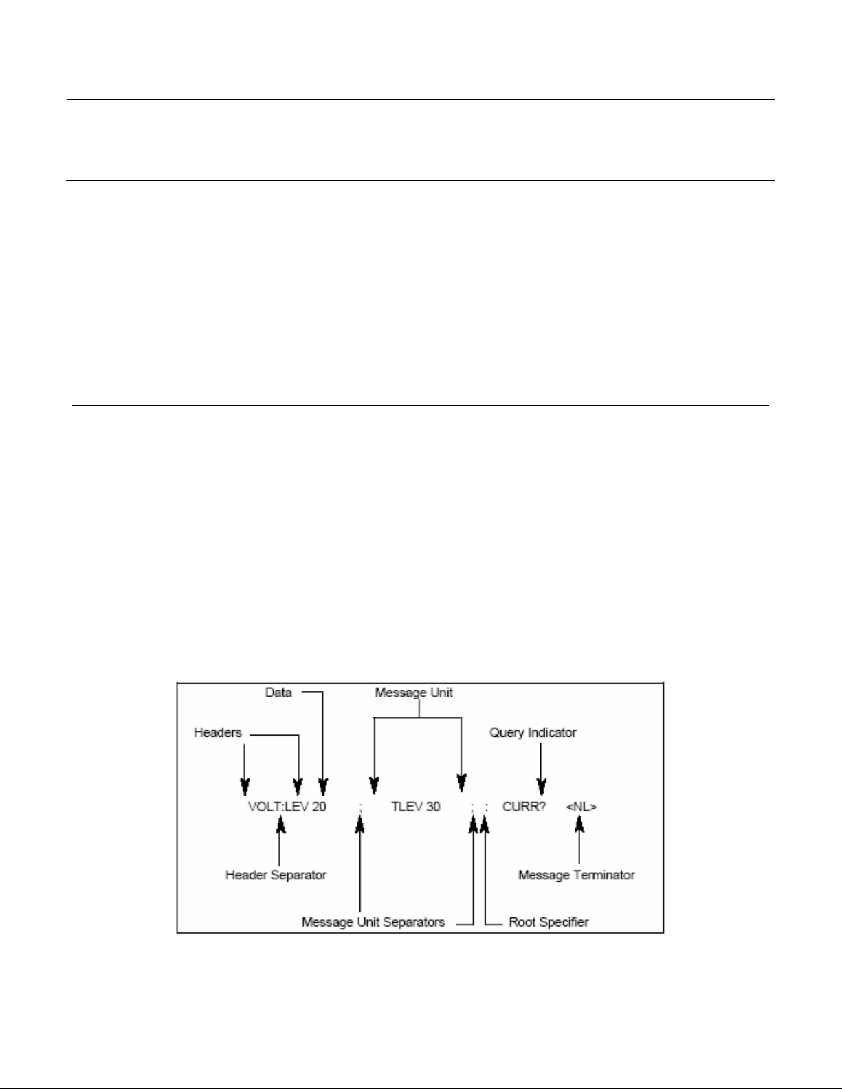
The following figure illustrates SCPI message structure:
Figure 5 - SCPI Message Structure
Other manuals for 8600 Series
1
This manual suits for next models
3
Table of contents
Other B+K precision Laboratory Equipment manuals


Popular Laboratory Equipment manuals by other brands


J.P. SELECTA
J.P. SELECTA AUTESTER ST DRY PV-B print 18L manual

Amanngirrbach
Amanngirrbach ceramill liquid instruction manual

J.P. SELECTA
J.P. SELECTA DIGITAL-S instruction manual

Thermo Forma
Thermo Forma 3920 Operating and maintenance manual

SereneLife
SereneLife SLUVDISB50 user manual

Gema
Gema OptiFlow IG07-P operating instructions


