bpr Dialflow Regulator User manual

702-0084.14
October 2014
Dialflow Regulator
Instructions for Use
1304X12345
YYMM
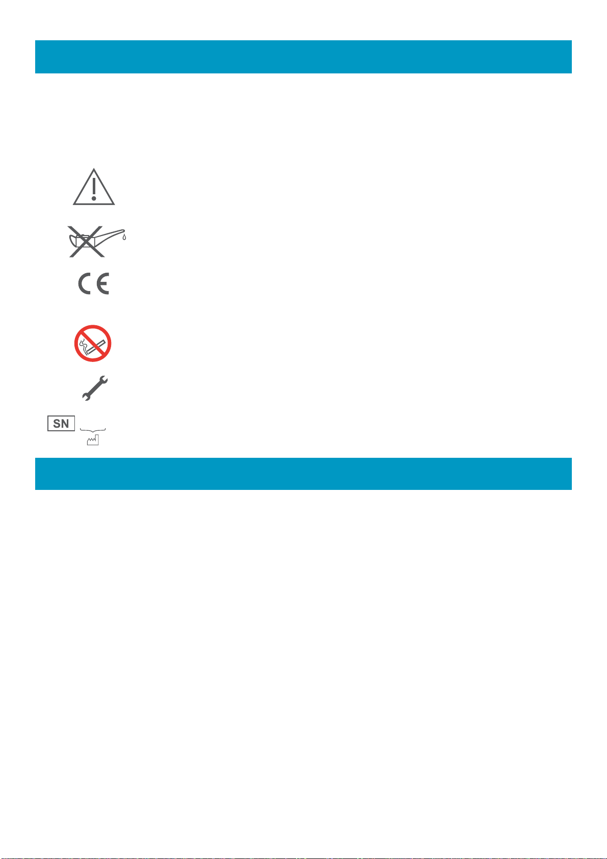
1. Symbols
Warning! Indicates a potentially hazardous situation which, if not avoided, could
result in personal injury to the user or others.
Caution! Indicates a potentially hazardous situation which, if not avoided, could
result in damage to the equipment or property.
Attention, consult accompanying documents
Use no oil
CE Marked to Medical Device Directive 93/42/EEC as amended by
directive 2007/47/CE
No smoking
Service due date
Date of manufacture identification
2. Warnings and Cautions
2.1. Warnings!
Read through this entire instruction manual before using or showing others how to use a
Dialflow Regulator. As with all medical equipment, attempting to use this device without a
thorough understanding of its operation may result in patient or user injury.
Medical oxygen is, or should be considered, a drug and may be used in critical
treatments. Medical gases should only be used for medical purposes on the authority of a
physician or authorised clinician and then strictly in accordance with their instructions.
Oxygen is not flammable however an oxygen enriched atmosphere will drastically
increase the rate and severity of combustion. Oil and/or grease in the presence of an
oxygen enriched atmosphere will become highly combustible. Oxygen must never be
allowed to contact oil, grease or other hydrocarbon based substances. Do not use oil or
grease on this Dialflow Regulator.
Never administer oxygen while smoking or when near an open flame.
Oxygen therapy may be a critical treatment. A regulated flowmeter should be used in
strict accordance with the prescription and instructions of a physician. The effectiveness
of supplemental oxygen therapy can only be determined by continuous monitoring of
blood oxygen levels. It is essential that PaO2 or SpO2 monitoring is carried out when
supplemental oxygen is prescribed.
0120

The use of the BPR Medical oxygen regulators for gases other than compressed oxygen
is expressly prohibited.
Never permit compressed medical gases to enter a regulator suddenly. Always open the
cylinder valve slowly.
Never use medical gases from a cylinder without reducing the pressure through a suitable
regulator intended for that gas.
Always close the cylinder valve when the regulator is not in use.
Never use oxygen as a pressure medium to purge obstructed pipelines or equipment,
operate pneumatic tools or to build up any pressure in tanks.
Never install a pin index regulator Dialflow Regulator with more than one yoke seal
between the valve and the regulator. Before attaching the regulator, verify that the post
valve is not already fitted with a yoke seal.
Ensure that you have the correct regulator for the type of cylinder you are intending to
use. Never attempt to fit a regulator to an incompatible cylinder.
Ensure that the threaded fittings or indexing pins on the regulator are properly mated and
tightened before opening the cylinder valve.
Do not stand in front of a regulator outlet when opening the cylinder valve.
Before removing a regulator from a cylinder, fully close the cylinder valve and release all
gas from the regulator.
Secure cylinders to a wall, stand or cart.
Do not use or store oxygen equipment near excessive heat (>50 °C or 125 °F) or open
flame.
Only appropriately trained personnel working in controlled conditions must perform
disassembly, assembly and testing of regulators and flowmeters.
Dialflow Regulators are not MRI compatible.
Flowmeters may be affected if the cylinder pressure is other than stated in the
specifications.
The threaded bull nose cylinder connection for medical oxygen and medical air may be
the same, ensure that you have the correct cylinder for the application. This regulator is
only intended for use with oxygen.
The holes in the side of the body of the device are for venting gas in the event that the
relief valve is activated. Do not obstruct these holes or interfere with the relief valve in
any way.
These regulators are designed for use for cylinder pressures up to 20 000 kPa
(3000 psi/200 bar). Do not attempt to connect BPR regulators to cylinders having fill
pressures in excess of this value.
Do not submerge the device in any fluid. Ensure that no fluid is allowed to enter the inlet
valve or the vent holes.
Ensure the device is not set between flow settings. If set between flow settings failure to
provide therapy may occur. Display of flow value does not indicate flow is occurring.
2.2. Cautions!
Device performance may be affected if it is stored or transported in temperature outside of
the range -20 °C to +60 °C (-4 °F to +140 °F).
The Dialflow Regulator is not suitable for autoclaving.

Cylinder Contents/
Pressure Gauge
Flow Selection Dial
Outlet Barb
Cylinder
Connection
3. Functional Description
3.1. Intended Use
The Dialflow Regulator is intended to deliver medical oxygen at one of eleven pre-set
rates directly from a high pressure oxygen cylinder. Flow is indicated in litres per minute
(l/min) and is visible through a window adjacent to the flow selection dial.
Medical oxygen is or should be considered a drug and should only be used for medical
purposes on the authority of a physician and then strictly in accordance with their
instructions. Always refer to the medical oxygen product labelling.
3.2. Technical Description
The Dialflow Regulator reduces the high pressure of the oxygen cylinder to a safe, more
manageable pressure for application to patients. There are many types of oxygen
cylinder connection used and these may be different from one country to another, ensure
that this regulator is the correct connector for the cylinder to be used.
Once connected to an oxygen cylinder, and with the cylinder valve opened, the user may
select the flow rate prescribed by rotating the gas flow selection dial until the correct flow
rate is seen in the viewing window.
The rate at which gas flows from the regulator is controlled by a hole of known size and
accuracy. Each flow rate has a different size hole. The output connector allows the user
to connect an oxygen facemask, cannula or other application device as appropriate.
4. Operating Instructions
4.1. Preparation and Connection
Check that the cylinder type and regulator inlet connector are compatible. Check the
presence and condition of the input connector seal, which for pin index regulators is a
washer type seal (Bodoc) and for bullnose regulators and O-ring.
Fit the regulator to the cylinder ensuring that it is properly mated and the connectors are
done up hand tight.
Flow Indication Window
Vent

Turn the gas flow selection dial fully clockwise and check that the indication in the
flowmeter window is zero.
Open the cylinder valve slowly with a suitable cylinder key. Check the regulator cylinder
contents gauge to verify that there is sufficient gas available.
Connect a sufficient length of oxygen tubing (not supplied) to the outlet barb.
4.2. Test Prior to Use
Turn the flow selection dial to its highest setting and check that gas flow can be felt at the
patient end of the tubing. If no medical oxygen flow is refer to Section 7 Troubleshooting
of this manual.
Turn off the oxygen flow by turning the flow selection dial fully clockwise.
4.3. Operation
Connect the free end of the oxygen tubing to the patient or patient enclosure using the
appropriate connector (not supplied).
Determine the appropriate oxygen flow rate in litres per minute (l/min) require for the
patient. Turn the flow selection dial until the required rate is visible in the flow indication
window; the dial ‘clicks’ into place and is obvious to the touch.
Continue to monitor the patient as advised by the clinician. Check the regulator contents
gauge regularly.
4.4. After Use
Upon completion of the therapy, turn the flow selection dial to zero, close the cylinder
valve and disconnect the outlet hose from the regulator and the patient.
To remove the regulator from the cylinder, first ensure the cylinder valve is closed. Bleed
off any residual gas pressure in the regulator by turning the flow selection dial to any flow
setting until flow ceases. Remove the regulator from the cylinder.
5. Maintenance
5.1. Interim Inspection
All Dialflow Regulators should be inspected and tested on an annual basis to ensure
correct performance.
5.1.1. Cleaning
Wipe down the outside of the device with an alcohol wipe. Do not allow the ingress of
water or other solution into the device. Check the exterior condition of the device. Pay
particular attention to the input connector seals, which should be replaced if damaged or
missing. Check that the holes in the side of the device, which are designed to vent gas in
the event of relief valve activation, are not obstructed or have otherwise been tampered
with.
5.1.2. Internal Leak Test
Connect the regulator to a cylinder in accordance with this Instructions for Use. Set the
flow selection dial to zero and open the cylinder valve. Connect a hose to the outlet barb
and immerse the other end of the hose into water. Check for leak through (internal leak).
Remove the hose.
This manual suits for next models
4
Table of contents
Other bpr Medical Equipment manuals


Popular Medical Equipment manuals by other brands


Getinge
Getinge Arjohuntleigh Nimbus 3 Professional Instructions for use

Mettler Electronics
Mettler Electronics Sonicator 730 Maintenance manual

Pressalit Care
Pressalit Care R1100 Mounting instruction

Denas MS
Denas MS DENAS-T operating manual

bort medical
bort medical ActiveColor quick guide

AccuVein
AccuVein AV400 user manual


