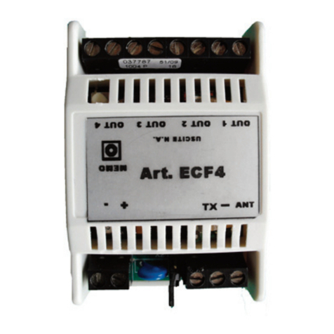
Elvox ECA7 User manual

Art. ECA7
Cod. S6I.ECA.700 RL.02 12/2010
FGBI
MANUALE D’INSTALLAZIONE E USO - CONTROL UNIT FOR SWING GATES - MANUEL D'INSTALLATION ET D'UTILISATION
CENTRALINA DI COMANDO PER ANTE BATTENTI
CONTROL UNIT FOR SWING GATES
UNITÉ DE COMMANDE POUR PORTES BATTANTES
Il prodotto è conforme alla direttive europee 89/336/CEE, 92/31/CEE, 93/68/CEE, 73/23/CEE, 98/37/CEE, R&TTE 99/05/CE, 89/106/CE.
The product is conform to the european directives 89/336/CEE, 92/31/CEE, 93/68/CEE, 73/23/CEE, 98/37/CEE, R&TTE 99/05/CE, 89/106/CE,
Le produit est conforme à la norme européenne 89/336/CEE, 92/31/CEE, 93/68/CEE, 73/23/CEE, 98/37/CEE, R&TTE 99/05/CE, 89/106/CE,.

M1 M2
+
-
C
C
Alimentazione motore 230V
Motor supply voltage 230V
Alimentation moteur 230V
Elettroserratura 12V
12V electric lock
Serrure électrique 12V
Comandi Contatti N.A.
Commands contact N.A.
Commandes N.A.
Sicurezze Contatti N.C.
Safety devices contact N.C.
Sécurités N.C.
Motori elettrici
monofase 230V
230V single-phase
electric motors
Moteurs électriques
monophasés 230V
Alimentazione accessori max. 0,3A
Accessories max power supply 0.3A
Alimentation accessoires maxi. 0,3A
Segnalazioni lampeggiante 12V 5W
Flashing light signals 12V 5W
Signalisations clignotant 12V 5W
Antenna
Aerial
Antenne
ECA7
2/20

INSTALLAZIONE ELETTRICA
La centralina di comando è alimentata a 230V. Gli attuatori sono alimentati a 230V e le uscite sono protette da due fusibili: F1, F2 da 4A.
Gli accessori sono alimentati a 12Vcc e le uscite sono protette da due fusibili: F3 e F4 da 2A.
Temperatura di funzionamento -20 ÷ +55°C. Per cablaggi con lunghezza superiore a 15 metri usare conduttori di sezione 2x4 mm².
Ciascun dispositivo deve essere installato a regola d’arte, seguendo le istruzioni allegate e soprattutto fare eseguire la messa in opera da
personale qualificato Elvox rispettando la normativa vigente in ciascun paese.
Collegamenti elettrici:
1 - Inserito l’attuatore eseguire i collegamenti seguendo le operazioni riportate nella centralina ECA7 (Fig. 1).
2 - Scegliere percorsi brevi per i collegamenti con cavo multipolare del tipo previsto dalle normative.
3 - L’impianto di messa a terra del cancello deve essere conforme alle norme vigenti.
La casa costruttrice declina ogni responsabilità per danni derivanti da eventuali negligenze in materia.
4 - In accordo con la normativa europea in materia di sicurezza si consiglia di inserire un interruttore bipolare di rete per poter togliere
l’alimentazione in caso di manutenzione del cancello e di scollegare il morsetto delle alimentazioni della scheda.
5 - Verificare che ogni singolo dispositivo (fotocellule, selettore a chiave, ecc.) sia efficiente ed efficace.
6 - Applicare adeguate misure integrative di sicurezza all’automazione se il caso lo richiede.
Collegamenti elettrici
Descrizione morsetti della scheda di comando EC70 (centralina Art. ECA7).
Quadro elettronico di comando per il controllo di 1 o 2 motori 230V con potenza non superiore a 250W cadauno.
N.B.: per determinare i punto di apertura e chiusura sono necessari dei fermi meccanici posti in apertura e chiusura desiderata
(Art. ZD27).
INSTALLAZIONE MECCANICA
Per una corretta istallazione fissare il box in in un luogo sicuro e al riparo dagli agenti atmosferici. Per fissare il box nella parete bisogna
togliere le 4 viti in plastica, aprire il coperchio e togliere i 4 tappi di plastica (copri vite). Fissato il box al muro con 4 tasselli rimetere i 4 tappi
di plastica (copri vite).
MISURE DI INGOMBRO ECA7
ECA7
3/20
FIG. 1

CARATTERISTICHE ELETTRICHE
Alimentazione rete : 230 Vac (6%,-10%)
Frequenza : 50 Hz
Alimentazione motore : 230 Vac
Potenza Max Motore : 250W
Velocità Max Motore : 1350 RPM
Corrente Max morsetti +12V -12V : 300 mA
Potenza Max. morsetti AUX COM2 : 1 W (12 Vcc)
Potenza Max. morsetti 2CAN COM2 : 1 W (12 Vcc)
Potenza Max. lampeggiante, LAMP : 5 W (12 Vcc)
Temperatura di esercizio : -20 +55 °C
DESCRIZIONE MORSETTI DELLA SCHEDA
VAC VAC
Morsetti dove vengono collegati i cavi provenienti dalla tensione di rete a 230Vac per l’alimentazione della scheda.
COM APM1 CHM1
Morsetti dove va collegato il primo motore. In caso di automazione con un solo motore questo va inserito solo in questi morsetti.
COM APM2 CHM2
Morsetti dove va collegato il secondo motore.
2CAN +COM2
Morsetti che danno in uscita una tensione con cui si può pilotare un relè 12V. L’attivazione avviene tramite il secondo pulsante del radio-
comando previa programmazione del codice nella scheda.
SER1 SER2
Morsetti dove viene collegata la serratura. La tensione è protetta tramite fusibile.
AUX +COM2
Morsetti che danno in uscita una tensione con cui si può pilotare un relè 12V. Normalmente l’attivazione avviene durante la corsa dell’au-
tomazione.
LAMP +COM2
Morsetti dove si collega il lampeggiante. La potenza massima consentita è di 5W. Il lampeggiante viene utilizzato per segnalare l’automazione
in movimento ma anche per dare delle indicazioni sullo stato in cui si trova l’automazione stessa. Di seguito si riportano delle modalità di
funzionamento. Se il cancello è in movimento il lampeggiante lampeggia, se il cancello è tutto aperto in attesa di richiudere il lampeggiante
è acceso a luce fissa. Se il cancello è tutto aperto con la chiusura automatica disabilitata il lampeggiante è spento. Se il cancello è tutto aperto
e si attivano le fotocellule il lampeggiante lampeggia. Se il cancello è parzialmente aperto o completamente aperto e sono aperti i contatti
STOP, ST.PA o FCEL il lampeggiante lampeggia. A cancello completamente aperto con chiusura automatica abilitata, se si ripristina il con-
tatto di STOP il lampeggiante si spegne, se si ripristina il contatto ST.PA o il contatto FCEL il lampeggiante lampeggia.
+12V -12V
Morsetti dove si collegano le fotocellule. presentano una tensione in uscita di circa 12Vdc con una corrente massima ammessa di 300mA.
APCH COM1
Sono i morsetti per attivare il movimento dell’automazione tramite pulsante o selettore.
APED COM1
Sono i morsetti per far aprire solamente la prima anta dell’automazione nel caso di 2 motori o l’anta del 30% se abbiamo solo 1 motore.
Ad apertura avvenuta si ferma e rimane aperta in attesa di nuovo comando (radiocomando, pulsante APCH, ecc.). Se durante la chiusura
si interrompe la corsa con le fotocellule il cancello riapre come con l’attivazione col morsetto APED stesso. Se in chiusura si dà un comando
di apertura normale (AP/CH, radiocomando) il cancello esegue l’apertura totale.
STOP COM1
Morsetto normalmente chiuso verso il morsetto COM1. Agisce sia in apertura che in chiusura, quando si apre L’automazione si blocca (o
rimane sempre chiusa o sempre aperta) e si disabilita anche il tempo di chiusura automatica. Quando il contatto STOP ritorna chiuso, a
nuovo comando l’automazione inverte il moto (chiude se stava aprendo, apre se stava chiudendo) e ripristina la chiusura automatica per
il comando successivo.
FOTO COM1
Morsetto dove viene collegato il contatto normalmente chiuso delle fotocellule col morsetto COM1. Agiscono solamente nella fase di chiu-
sura del cancello. Se il cancello stava chiudendo, l’attivazione delle fotocellule (apertura del contatto verso COM1) fa riaprire completa-
mente il cancello.
ST.PA COM1
Si comporta come le fotocellule ma solamente in apertura. Se il contatto normalmente chiuso tra i morsetti ST.PA e COM1 si interrompe
l’automazione si blocca. Quando si ripristina il contatto l’automazione riprende il moto di apertura senza disabilitare la chiusura automa-
tica se impostata. In questa situazione il lampeggiante lampeggia se il contatto rimane aperto. Se viene dato un comando di AP/CH o da
radiocomando il cancello chiude a meno che non sia impostata la funzione condominiale. Ad automazione chiusa anche se il contatto ST.PA
è aperto il lampeggiante rimane spento. Ad un comando di apertura il lampeggiante lampeggia.
TXRX -GND
Morsetti dove si può collegare un PC tramite interfaccia 6952/A.
ANT -GND
Morsetti dove si può collegare un cavetto, solo su ANT, o antenna, art. ZL43, per migliorare il livello di ricezione del segnale.
ECA7
4/20
I

DIAGNOSI DEL CABLAGGIO DELL’IMPIANTO
La centralina è gestita da un microprocessore ed è dotata di diagnosi visiva tramite Led per controllare lo stato degli ingressi e delle uscite.
1. Controllare tutti i collegamenti prima di alimentare la scheda.
2. Gli ingressi NC non utilizzati devono essere ponticellati.
3. Alimentata la scheda verificare che i led verdi posizionati sopra alla morsettiera, nella parte inferiore destra della scheda, che indicano
gli ingressi NC siano accessi.
4. Verificare che i led rossi posizionati sopra alla morsettiera, nella parte inferiore destra della scheda, che indicano gli ingressi NA siano
spenti.
5. Led rosso posizionato sopra al centro, indica la presenza della tensione di rete, quindi deve essere accesso.
A questo punto l’apparecchiatura è pronta per funzionare.
FUNZIONAMENTO
In base al settaggio dei dip–switch, ad automazione ferma e chiusa un comando fa iniziare la marcia. La prima manovra viene effettuata in
apertura.L’automazione apre per tutto il tempo di lavoro impostato, al termine dell’apertura il cancello si ferma e, se impostata la chiusura
automatica, al termine del tempo di pausa, richiude.
FOTOCELLULE
Durante l’apertura l’intervento delle fotocellule non provoca alcuna alterazione del moto (se non programmate in modo diverso ST.PA),
mentre in chiusura ne provoca l’inversione fino alla completa riapertura, per poi completare la chiusura dopo il tempo di pausa.
APERTURA PEDONALE
Il comando di Apertura Pedonale dipende dal settaggio del DIP che indica se la scheda funziona ad un motore oppure a 2 motori. In caso
di 1 motore si aprirà del 30% della corsa normale se non diversamente programmato. In caso di 2 motori si aprirà solamente l’anta 1.
FUNZIONE “COLPO D’ARIETE”
Se impostato tramite DIP, prima di iniziare l’apertura l’anta 1 chiude ancora per circa 1.5” per sbloccare la serratura. In chiusura non è ne-
cessario dare una spinta diversa perché il motore è sempre a pieno regime (non c’è il rallentamento). Anche se non impostato il colpo
d’ariete, alla partenza la serratura si attiva per circa 5”.
PROGRAMMAZIONE CORSA E TEMPO PAUSA
N.B.: Prima di eseguire l’apprendimento della corsa posizionare le ante leggermente aperte.
Questa operazione è necessaria per il corretto funzionamento dell’automazione. Si tratta di programmare lo spazio da percorrere quanti-
ficandolo in tempo di percorrenza. Si effettua una apertura ed una chiusura dell’automazione. Il tempo percorso viene poi memorizzato
nel microcontrollore della scheda.
Si posiziona l’ante circa a meta della corsa (questo per controllare il corretto collegamento del motore alla scheda) sbloccando manual-
mente il motore ruotando la levetta di sblocco idraulico del motore.
Si preme il tasto RESET e poi si entra in programmazione corsa come di seguito indicato:
Si premono i tasti MEMO ed il tasto RESET contemporaneamente ed il led PROG si accende di rosso, si rilascia il tasto RESET e si tiene
premuto il tasto MEMO finchè il led PROG. da rosso diventa verde. A questo punto si rilascia il tasto MEMO e si attende che il led verde
lampeggi.
Si dà il comando di inizio premendo il tasto AP/CH della scheda, il motore parte e chiude l’anta 1 (in caso che l’anta si apra invece di chiu-
dere bisogna invertire i cavi di collegamento del motore. Si preme di nuovo il tasto AP/CH ed il motore inverte automaticamente il moto
aprendo l’anta. Quando l’anta arriva nella posizione di apertura desiderata, si preme di nuovo il tasto AP/CH per fermarla. Si preme nuo-
vamente il tasto AP/CH e l’anta 2 esegue le stesse operazioni dell’anta 1 (chiude fino al fermo in chiusura, si preme il tasto AP/CH, riapre
e alla fine si ripreme il tasto AP/CH per fermare l’anta 2 in apertura completa). A questo punto parte il conteggio del tempo di pausa tra
apertura e chiusura. Terminata l’attesa del tempo di pausa si ripreme il tasto AP/CH per far richiudere l’anta 2. Si attende il tempo di sfa-
samento e si preme il tasto AP/CH, l’anta 1 comincia a chiudere. L’anta 2 termina la corsa in chiusura, si preme il tasto AP/CH, l’anta si
ferma. Si attende che anche l’anta 1 raggiunga il fermo in chiusura e si ripreme il tasto AP/CH per fermare anche il motore 1. La program-
mazione è finita. Se tutto è andato a buon fine il led verde si spegne.
RADIOCOMANDI
La centralina accetta e memorizza fino a 250 codici radio. Quando la memoria è esurita il tentativo di memorizzare un nuovo codice fa sì
che si esca automaticamente dalla programmazione. La centralina è predisposta per accettare sia codici di tipo tradizionale e sia codici di
tipo rolling-code. E’ sufficiente inserire nell’apposito connettore il modulo opzionale di tipo tradizionale, art. ECRF, o rolling-code, Art.ECRR.
PROGRAMMAZIONE CODICI RADIO
I codici radio sono utilizzabili quando è presente nella scheda la schedina opzionale dedicata a questo compito.
Si entra in programmazione codici radio la scheda procedendo come di seguito indicato: si premono contemporaneamente il tasto RESET
ed il tasto della schedina opzionale, si rilascia il tasto RESET e si tiene premuto il tasto della schedina radio finché si accende il led verde
della schedina. A questo punto si rilascia il tasto della schedina e si preme il tasto del radiocomando che si vuole memorizzare. Il buon fine
dell’operazione viene segnalato dal led verde che fa un lampeggio e poi rimane acceso. Se si inserisce un altro codice diverso dai prece-
denti il led verde fa un altro lampeggio e rimane acceso.
Alla fine della programmazione si preme il tasto RESET per uscire dalla programmazione.
ECA7 I
5/20

CANCELLAZIONE CODICI RADIO
Questa procedura permette la cancellazione di tutti i codici memorizzati. La cancellazione del singolo codice non è permessa. Si procede
come di seguito indicato: si preme il tasto RESET, si preme il tasto della schedina radio Art.ECRR e si tiene premuto finchè si accende il
led verde, si lascia il tasto della schedina e poi si ripreme finchè si accende il led verde lampeggiante. A questo punto si lascia il tasto della
schedina e poi si ripreme ancora finchè il led verde lampeggia più velocemente. In questo momento i codici radio vengono tutti cancellati.
Il led verde si spegne. Per interrompere questa procedura si preme il tasto RESET prima della fine del processo oppure si toglie alimenta-
zione alla scheda. E’ possibile cancellare un solo codice radio solamente nel caso di codici fissi, utilizzando il programma Analyzer e
l’interfaccia Art.6952/A.
REGOLAZIONI SULLA SCHEDA
DIP SWITCH
Ci sono 12 Dip-Switch che regolano il funzionamento basilare della scheda. I valori dei dip-switch vengono letti quando la scheda è ali-
mentata, premendo il tasto reset della scheda.
Dip 1 Ritardo ante in apertura
OFF Ritardo tra la partenza della prima anta e della seconda di circa 3”
ON Nessun ritardo in partenza (doppio scorrevole)
Dip 2 Chiusura automatica
OFF Non inserita
ON Inserita
Dip 3 Funzione Condominiale (vince su dip 5)
OFF Funz. Normale come da dip 5
ON Sino ad apertura totale accetta solo il comando apre, in chiusura un nuovo comando inverte la marcia della corsa
Dip 4 Colpo d’ariete
OFF Escluso
ON Con impulso di apertura l’anta 1 chiude ancora per circa 1.5” per sbloccare l’elettroserratura e poi inizia l’apertura.
Dip 5 Apre / Stop / Chiude
OFF Un impulso Apre, uno Chiude
ON Un impulso Apre, uno Stop e uno Chiude
Dip 6 Apertura Pedonale da radiocomando
OFF Il secondo canale attiva l’uscita 2CAN
ON Il secondo canale attiva l’apertura Pedonale (se 2 motori apre tutta la prima; se a 1 motore apre l’anta del 30%)
Dip 7 Prelampeggio
OFF Prelampeggio escluso
ON Prelampeggio inserito
Dip 8 N. MOTORI
OFF Automazione a 2 motori
ON Automazione a 1 motore
Dip 9 Comando pedonale sdoppiato
OFF Comando APED normale
ON Il comando APED (sia da pulsante che da radiocomando se impostato) fa partire la prima anta ad un comando e anche la seconda anta al secondo co-
mando ricevuto dalla scheda entro un tempo fisso di circa 7”
Dip 10 Non Utilizzato
Dip 11 Non Utilizzato
Dip 12 Rolling-code
OFF Funzionamento con il ricevitore tradizionale a DIP-SWITCH.
ON Funzionamento a Rolling-Code
ECA7
PARAMETRI OPZIONALI
Altri parametri utili per il funzionamento dell’automazione sono impostabili con l’interfaccia PC e il programma Analyzer (Art.6952/A).
VALUTAZIONE FUNZIONAMENTO DELLE FOTOCELLULE
Periodicamente, se abilitato tramite parametro, viene tolta l’alimentazione delle fotocellule (morsetti +12 -12) e si valuta se in questa con-
dizione il contatto delle fotocellule normalmente chiuso, si apre. Se non si apre significa che le fotocellule sono guaste e viene mandata
una segnalazione via seriale al PC. Il test avviene solamente se l’automazione è a riposo. Altrimenti si salta il ciclo al periodo successivo
6/20
I

ECA7
Electronic control panel for control of 1 or 2 230V motors, each with maximum power of 250W.
NOTE: in order to determine the opening and closing points, mechanical stops must be fitted at the desired opening and closing
positions (type ZD27).
MECHANICAL INSTALLATION
For correct installation, fix the box in a secure place where it is protected from the weather. To mount the box on the wall remove the 4 pla-
stic screws, open the cover and remove the 4 plastic screw caps. After fastening the box to the wall with 4 plugs, refit the 4 plastic screw
caps.
OVERALL DIMENSIONS ECA7
ELECTRICAL INSTALLATION
The control unit is powered at 230V. The actuators are powered with 230V and the outputs are protected by two fuses: a 4A fuse (F1, F2).
The accessories are powered with 12Vdc and the outputs are protected by two fuses: F3 and F4 at 2A.
Operating temperature -20 ÷ +55°C. For cables of more than 15 metres in length, use 2x4mm2wires.
Each device must be expertly installed, following the enclosed instructions and above all must be set up by qualified Elvox Automation Di-
vision approved personnel in accordance with the standards in force in each individual country.
Electrical connection:
1 -After inserting the actuator, make the connections following the steps indicated in control unit ECA7 (Fig. 1).
2 - Select short routes for the connections with a multicore cable compliant with applicable regulations.
3 - The gate’s earthing device must conform to the standards in force. The manufacturer will not accept responsibility for damage arising
from negligence in this respect.
4 - In accordance with European safety standards, it is recommended that an external two-pole switch is installed so that the power sup-
ply to the gate during maintenance and the power terminal on the card may be disconnected.
5 -Check that each individual device (photocells, key selector, etc.) works correctly and efficiently.
6 - Apply adequate integrated safety measures to the automatic system where required.
Electrical connections
Description of EC70 control card terminals (control unit type ECA7).
GB
7/20
Fig. 1

ECA7
ELECTRICAL SPECIFICATIONS
Mains power supply : 230 Vac (6%,-10%)
Frequency : 50 Hz
Motor power supply : 230 Vac
Max power motor : 250W
Max speed motor : 1350 RPM
Max current terminals +12V -12V : 300 mA
Max power terminals AUX COM2 : 1 W (12 Vdc)
Max power terminals 2CAN COM2 : 1 W (12 Vdc)
Max power flashing light, LAMP : 5 W (12 Vdc)
Operating temperature : -20 +55 °C
DESCRIPTION OF CARD TERMINALS
VAC VAC
Terminals where the cables from the 230Vac mains power supply for powering the card are connected.
COM APM1 CHM1
Terminals where the first motor must be connected. In the case of automatic gate systems with a single motor, the motor must only be
plugged into these terminals.
COM APM2 CHM2
Terminals where the second motor must be connected.
2CAN +COM2
Terminals that output a voltage to be used to control a 12V relay. Activation is by means of the second radio control push-button, provi-
ded that the code has been programmed in the card.
SER1 SER2
Terminals where the lock is connected. The voltage is protected by means of a fuse.
AUX +COM2
Terminals that output a voltage to be used to control a 12V relay. Activation normally occurs when the automation is moving.
LAMP +COM2
Terminals where the flashing light is connected. The maximum permissible power is 5W. The flashing light is used to indicate that the au-
tomation is moving but also to indicate the operating status of the automatic gate system. The operating modes are as follows: If the gate
is moving, the flashing light blinks. If the gate is fully open waiting to close, the flashing light stays on with a steady light. If the gate is fully
open with automatic closing disabled, the flashing light is off. If the gate is fully open and the photocells activate, the flashing light blinks.
If the gate is partly open or fully open and the STOP, ST.PA or FCEL contacts are open, the flashing light blinks. With the gate fully open
and automatic closing enabled, if the STOP contact is reset the flashing light goes out, if the ST.PA contract or the FCEL contact is reset
the flashing light blinks.
+12V -12V
Terminals where the photocells are connected. They have an output voltage of approximately 12Vdc with a maximum permissible current
of 300mA.
APCH COM1
These are the terminals for activating the movement of the automatic gate system via a button or switch.
APED COM1
These terminals open only the first gate leaf in the case of automatic systems with 2 motors, or open the gate leaf to 30% of normal tra-
vel in the case of automatic systems with only 1 motor. After opening it stops and stays open waiting for a new command (radio control,
OP/CL push-button, etc.). If, while closing, its travel is stopped by the photocells, the gate reopens in the same way as activation with the
APED terminal. If on closing, a normal opening command is given (OP/CL, radio control), the gate opens completely.
STOP COM1
Normally closed contact to terminal COM1. It activates on both opening and closing; when it opens, the automatic gate system stops (or
remains permanently closed or permanently open) and the automatic closing time is also disabled. When the STOP contact returns to the
closed position, on receiving a new command the automatic gate system reverses its motion (it closes if it was opening or opens if it was
closing) and restores automatic closing for the next command.
FOTO COM1
Terminal where the normally closed contact of the photocells is connected with terminal COM1. They are only activated when the gate is
closing. If the gate was closing, the activation of the photocells (opening the contact towards COM1) makes the gate open fully.
ST.PA COM1
It behaves like the photocells, but only on opening. If the normally closed contact between terminals ST.PA and COM1 breaks, the auto-
matic gate system shuts down. When the contact is reset the automatic gate system starts opening again without disabling automatic clo-
sing if this is set. In this situation the flashing light blinks if the contact stays open. If an OP/CL or radio control command is given, the gate
closes unless the condominium function is set. When the automatic gate is closed, even if the ST.PA contact is open the flashing light re-
mains off. In response to an opening command the flashing light blinks.
TXRX -GND
Terminals where a PC can be connected by means interface Art. 6952/A..
ANT -GND
Terminals for connection of a cable, only on ANT, or an aerial, type ZL43, to improve signal reception.
8/20
GB

ECA7
SYSTEM WIRING FAULT DIAGNOSIS
The control unit is managed by a microprocessor and provides visual diagnostics via LEDs for checking the status of the inputs and out-
puts.
1. Check all connections before supplying power to the board.
2. Unused NC inputs must be jumped.
3. After powering up the board, check that the green LEDs located above the terminal block in the lower right-hand part of the board, which
indicate the NC inputs, are ON.
4. Check that the red LEDs located above the terminal block in the lower right-hand part of the board, which indicate the NO inputs, are
OFF.
5. The red LED, positioned above and to the centre of the display, indicates the presence of mains voltage and therefore must be ON.
At this point the appliance is ready to operate.
OPERATION
Based on the setting of the DIP-switches, when the automatic gate system is stationary and closed a command starts it opening. The first
manoeuvre is performed on opening. The automatic gate system opens for the full configured operating time; at the end of the opening
movement the gate stops and, if automatic closing is set, it closes when the dwell time has elapsed.
PHOTOCELLS
During opening the photocells tripping causes no change in motion (unless ST.PA is programmed otherwise), whereas on closing it cau-
ses the gate to reverse its movement until fully open, then complete the closing movement after the dwell time.
PEDESTRIAN OPENING
The Pedestrian Opening command depends on the setting of the DIP-switch that indicates whether the card is operating with 1 motor or
2 motors. In the case of 1 motor the gate leaf will open to 30% of its normal travel unless programmed otherwise. In the case of 2 motors
only gate leaf 1 will open.
KICKBACK FUNCTION
If set via DIP-switch, before starting to open, gate leaf 1 closes again for around 1.5 seconds to release the lock. On closing a different thrust
is not required because the motor is still at full power (there is no slow-down). Even if the kickback function is not set, on starting the lock
is activated for approximately 5 seconds.
PROGRAMMING TRAVEL PATH AND DWELL TIME
NOTE: Before executing the travel path self-learning procedure, position the gate leaves so that they are slightly open.
This operation is necessary for the automatic gate system to work properly. It involves programming the travel path, quantifying it in travel
time. The automatic gate system performs one opening and closing cycle. The travel time is then saved in the card's microcontroller.
Position the gate leaf about midway along its travel path (this is to check that the motor is correctly connected to the card), manually re-
leasing the motor by turning the motor's hydraulic release lever.
Press the RESET button to enter the travel path programming mode as indicated below:
Simultaneously press the MEMO buttons and the RESET button, the PROG LED lights up red, release the RESET button and keep the
MEMO button pressed until the red PROG LED turns green. At this point release the MEMO button and wait for the green LED to start blin-
king. Give the start command by pressing the card's OP/CL button, the motor starts and closes leaf 1 (in the event that the leaf opens in-
stead of closing you need to swap over the motor connection wires). Press the OP/CL button once more and the motor automatically
reverses its motion, opening the gate leaf. When the gate leaf reaches the desired opening position, press the OP/CL button again to close
it. Press the OP/CL button again and leaf 2 performs the same steps as leaf 1 (it closes as far as the limit stop, press the OP/CL button, it
reopens and finally press the OP/CL button again to stop leaf 2 in the fully open position). At this point the dwell time countdown between
opening and closing starts. Wait for the desired dwell time, then press the OP/CL button again to close leaf 2. Wait for the desired delay
time then press the OP/CL button, leaf 1 starts to close. Leaf 2 completes its closing travel path, press the OP/CL button, the leaf stops.
Wait until leaf 1 also reaches the closing limit stop and press the OP/CL button again to stop motor 1. Programming is complete. If the pro-
cedure was completed successfully, the green LED will go out.
RADIO CONTROLS
The control unit accepts and saves up to 250 radio codes. When the memory is full, any attempt to store a new code causes the system
to exit programming mode. The control unit is preset to accept both conventional codes and rolling codes. Simply plug the optional mo-
dule for conventional codes, type ECRF, or the rolling-code module, type ECRR, into the corresponding connector.
PROGRAMMING RADIO CODES
Radio codes can be used when the card is fitted with the optional radio board. To put the card into radio code programming mode pro-
ceed as follows: simultaneously press the RESET button and the button on the optional board, release the RESET button and keep the radio
board button pressed until the board’s green LED lights up. Now release the board button and press the button of the radio control that
you want to store. The green LED indicates successful completion of the operation by blinking once and then remaining permanently lit. If
another code, different from the previous ones, is entered, the green LED blinks again and then remains permanently lit.
After finishing programming press RESET push-button to exit
GB
9/20

ECA7
GB
DELETING RADIO CODES
This procedure is used to delete all saved codes. Deleting individual codes is not permitted. Proceed as follows: press the RESET button,
press and hold down the button of radio board type ECRR until the green LED lights up, release the board button and then press it again
until the flashing green LED lights up. At this point release the board button and press it again until the green LED blinks faster. Now all of
the radio codes are deleted. The green LED turns off. To interrupt this procedure, press the RESET button before the end of the process
or disconnect the power to the card. It is only possible to delete individual radio codes in the case of fixed codes, using the Analyzer pro-
gram and interface type 6952/A.
ADJUSTMENTS ON THE CARD
DIP SWITCH
There are 12 DIP-switches that adjust the basic operation of the card. The DIP-switch values can be read when the card is powered, by
pressing the card's reset button.
OPTIONAL PARAMETERS
Other useful parameters for operation of the automatic gate system can be configured using the PC interface and the Analyzer program
(type 6952/A).
PHOTOCELL FUNCTIONAL TEST
On a periodic basis, if enabled via parameter, power to the photocells (terminals +12 -12) is cut off to test whether in this condition the nor-
mally closed contact of the photocells opens. If it does not open it means that the photocells are faulty and a signal is sent via serial link to
the PC. This test is only performed if the automatic gate system is at rest. Otherwise the test cycle will skip to the next scheduled period
Dip 1 Gate leaves opening delay
OFF Delay of approximately 3 secs. between the start of the first gate leaf and the start of the second.
ON No starting delay (double sliding gate)
Dip 2 Automatic closing
OFF Not inserted
ON Inserted
DIP 3 Condominium function (overrides DIP 5)
OFF Normal Operation as for DIP 5
ON Until the fully open position it only accepts the open command, on closing a new command reverses the direction of travel
DIP 4 Kickback
OFF Deactivated
ON
When an opening pulse is received leaf 1 closes again for approximately 1.5 seconds to release the electric lock and then starts
to open.
DIP 5 Open / Stop / Close
OFF One pulse Opens, one Closes
ON One pulse Opens, one Stops and one Closes
DIP 6 Pedestrian Opening from radio control
OFF The second channel activates the 2CAN output
ON
The second channel activates Pedestrian Opening (if 2 motors the first leaf opens fully if 1 motor the leaf opens to 30% of nor-
mal travel)
DIP 7 Pre-flashing
OFF Pre-flashing deactivated
ON Pre-flashing activated
DIP 8 No. MOTORS
OFF Automatic gate system with 2 motors
ON Automatic gate system with 1 motor
DIP 9 Split pedestrian command
OFF Normal APED command
ON
The APED command (both from push-button and from radio control if set) starts the first leaf with one command and also the
second leaf on the second command received by the card after a set time of approximately 7 seconds
DIP 10 Not Used
DIP 11 Not Used
DIP 12 Rolling code
OFF Operation with conventional DIP-SWITCH receiver.
ON Rolling code operation
10/20

CARACTÉRISTIQUES GÉNÉRALES
Tableau électronique de commande pour le contrôle de 1 ou 2 moteurs 230V avec puissance non supérieure à 250W chacun.
N.B.: pour déterminer les points d'ouverture et de fermeture, des arrêts mécaniques sont nécessaires, situés en ouverture et fer-
meture (Art. ZD27).
INSTALLATION MÉCANIQUE
Pour une installation correcte, fixer le boîtier dans un lieu sûr et à l'abri des agents atmosphériques. Pour fixer le boîtier au mur, enlever
les 4 vis en plastique, ouvrir le couvercle et ôter les 4 bouchons en plastique (cache-vis). Après avoir fixé le boîtier au mur avec 4 chevil-
les, remettre les 4 bouchons en plastique (cache-vis).
DIMENSIONS D’ENCOMBREMENT ART. ECA7
INSTALLATION ÉLECTRIQUE
L'unité de commande est alimentée à 230V. Les actionneurs sont alimentés à 230V et les sorties sont protégées par deux fusibles: F1, F2
de 4A. Les accessoires sont alimentés à 12 Vcc et les sorties sont protégées par deux fusibles : F3 et F4 de 2 A.
Température de fonctionnement -20 ÷ +55°C. Pour les câblages d'une longueur supérieure à 15 mètres, utiliser des conducteurs de sec-
tion 2x4 mm².
Chaque dispositif doit être installé dans les règles de l’art, selon les indications jointes et en particulier la mise en œuvre doit être effec-
tuée par du personnel qualifié de Elvox en respectant la réglementation en vigueur dans chaque pays.
Branchements électriques:
1. Une fois l'actionneur inséré, effectuer les branchements en suivant les opérations rapportées dans l'unité de commande ECA7 (Fig. 1).
2. Choisir de courtes distances pour les branchements avec câble multipolaire du type prévu par les normes.
3. Le système de mise à la terre de la grille doit être conforme aux normes en vigueur, le constructeur décline toute responsabilité pour
les dommages causés par des négligences éventuelles à ce sujet.
4. En accord avec la réglementation européenne en matière de sécurité, il est conseillé de placer un interrupteur bipolaire externe pour
pouvoir couper l’alimentation en cas d’entretien de la grille et débrancher la borne des alimentations de la carte.
5. Contrôler que chaque dispositif (cellules photoélectriques, sélecteur à clé, etc.) fonctionne bien et est efficace.
6. Si nécessaire, appliquer des mesures de sécurité complémentaires au mécanisme automatique.
Branchements électriques
Description bornes de la carte de commande EC70 (unité de commande Art. ECA7).
F
11/20
Fig. 1

ECA7
CARACTÉRISTIQUES ÉLECTRIQUES
Alimentation réseau 230 Vca (6 %,-10 %)
Fréquence 50 Hz
Alimentation moteur 230 Vca
Puissance max. moteur 250W
Vitesse max. moteur 1350 tr/min
Courant max. bornes +12 V, - 12 V 300 mA
Puissance max. bornes AUX COM2 1 W (12 Vcc)
Puissance max. bornes 2CAN COM2 1 W (12 Vcc)
Puissance max. clignotant, LAMP 5 W (12 Vcc)
Température de fonctionnement -20 +55°C
DESCRIPTION DES BORNES DE LA CARTE
VCA VAC
Bornes auxquelles sont reliés les câbles provenant de la tension de réseau à 230 Vca pour l’alimentation de la carte.
COM APM1 CHM1
Bornes auxquelles le premier moteur doit être relié. En cas d'automatisme avec un seul moteur, celui-ci doit être relié seulement à ces bornes.
COM APM2 CHM2
Bornes auxquelles le deuxième moteur doit être relié.
2CAN +COM2
Bornes qui donnent une tension en sortie permettant de piloter une relais de 12 V. L’activation s'effectue à l'aide du deuxième bouton de
la radiocommande après programmation du code dans la carte.
SER1 SER2
Bornes auxquelles la serrure est reliée. La tension est protégée par un fusible.
AUX +COM2
Bornes qui donnent une tension en sortie permettant de piloter un relais de 12 V. L'activation a normalement lieu pendant la course de
l'automatisme.
LAMP +COM2
Bornes auxquelles le clignotant doit être relié. La puissance maximum admise est de 5 W. Le clignotant est utilisé pour signaler que
l'automatisme est en mouvement mais aussi pour donner des indications sur son état. Les modes de fonctionnement sont indiqués ci-des-
sous. Si le portail est en mouvement, le clignotant clignote. Si le portail est entièrement ouvert en attente de se refermer, le clignotant reste
allumé de façon fixe. Si le portail est entièrement ouvert avec la fermeture automatique désactivée, le clignotant est éteint. Si le portail est
entièrement ouvert et les photocellules s'activent, le clignotant clignote. Si le portail est partiellement ouvert ou entièrement ouvert et les con-
tacts STOP, ST.PA ou FCEL sont ouverts, le clignotant clignote. Lorsque le portail est entièrement ouvert avec la fermeture automatique ac-
tivée, si le contact de STOP est rétabli, le clignotant s'éteint ; si le contact ST.PA ou le contact FCEL est rétabli, le clignotant clignote.
+12V -12V
Bornes auxquelles les photocellules doivent être reliées. Elles ont une tension en sortie de 12 Vcc environ avec un courant maximum
admis de 300 mA.
APCH COM1
Ce sont les bornes qui activent le mouvement de l'automatisme par bouton ou sélecteur.
APED COM1
Ce sont les bornes pour faire ouvrir seulement le premier vantail de l'automatisme en présence de 2 moteurs ou le vantail de 30 % en pré-
sence d'1 seul moteur. Après l'ouverture, il s'arrête et reste ouvert dans l'attente d'une nouvelle commande (radiocommande, bouton OU-
VERTURE/FERMETURE, etc.). Pendant la fermeture, si la course s'interrompt avec les photocellules, le portail s'ouvre à nouveau comme
avec l'activation de la borne APED. En fermeture, en cas de commande d'ouverture normale (OUVERTURE/FERMETURE, radiocom-
mande), le portail réalise l'ouverture totale.
STOP COM1
Borne normalement fermée vers la borne COM1. Agit en ouverture et en fermeture ; lorsqu'elle s'ouvre, l'automatisme se bloque (ou reste
toujours fermé ou toujours ouvert) et le temps de fermeture automatique se désactive également. Lorsque le contact STOP revient en po-
sition fermée, après une nouvelle commande, l'automatisme intervertit le mouvement (ferme s'il était en train d'ouvrir, ouvre s'il était en
train de fermer) et rétablit la fermeture automatique pour la commande suivante.
FOTO COM1
Borne à laquelle est relié le contact normalement fermé des photocellules avec la borne COM1. Elles agissent seulement pendant la fer-
meture du portail. Si le portail était en train de se fermer, l'activation des photocellules (ouverture du contact vers COM1) fait rouvrir com-
plètement le portail.
ST.PA COM1
Se comporte comme les photocellules mais seulement en ouverture. Si le contact normalement fermé entre les bornes ST.PA et COM1
s'interrompt, l'automatisme se bloque. Lorsque le contact est rétabli, l'automatisme reprend le mouvement d'ouverture sans désactiver
la fermeture automatique éventuellement définie. Dans cette situation, le clignotant clignote si le contact reste ouvert. Si une commande
d'OUVERTURE/FERMETURE ou par radiocommande est donnée, le portail se ferme sauf si la fonction copropriété a été programmée. Avec
l'automatisme fermé, même si le contact ST.PA est ouvert, le clignotant reste éteint. À une commande d'ouverture, le clignotant clignote.
TXRX -GND
Bornes auxquelles un PC peut être relié avec interface Art. 6952/A.
ANT -GND
Bornes auxquelles un petit câble peut être relié, seulement sur ANT, ou antenne, réf. ZL43, pour améliorer le niveau de réception du signal.
12/20
F

ECA7
DIAGNOSTIC DU CÂBLAGE DE L'INSTALLATION
L'unité de commande est gérée par un microprocesseur et est équipée de diagnostic visuel et leds pour contrôler l'état des entrées et des
sorties.
1. Contrôler tous les branchements avant d'alimenter la carte.
2. Les entrées N.F. non utilisées doivent être reliées par pontets.
3. Après avoir alimenté la carte, vérifier que les leds vertes positionnées sur le bornier, dans la partie inférieure droite de la carte, qui indi-
quent les entrées N.F. sont allumées.
4. Vérifier que les leds rouges positionnées sur le bornier, dans la partie inférieure droite de la carte, qui indiquent les entrées N.O. sont
éteintes.
5. Le leds rouges sur l'afficheur en haut en centre indique la présence de la tension de réseau ; par conséquent, il doit être allumé.
L'appareil est prêt à fonctionner.
FONCTIONNEMENT
Selon le paramétrage du dip–switch, avec l'automatisme à l'arrêt et fermé, une commande fait démarrer la marche. La première manœu-
vre est effectuée en ouverture. L'automatisme ouvre pendant toute la durée réglée ; en fin d'ouverture, le portail s'arrête et se referme à la
fin du temps de pause si la fermeture automatique est configurée.
PHOTOCELLULES
Pendant l'ouverture, l'intervention des photocellules ne provoque aucune altération du mouvement (si elles ne sont pas programmées de
façon différente ST.PA), alors qu'en fermeture, elle provoque l'inversion jusqu'à la réouverture complète pour conclure ensuite la fermeture
après le temps de pause.
OUVERTURE PIÉTONNE
La commande d'Ouverture Piétonne dépend du paramétrage du DIP qui indique si la carte fonctionne à un moteur ou à deux moteurs. En
fonctionnement à un moteur, elle s'ouvrira de 30 % par rapport à sa course normale, sauf programmation différente. En fonctionnement à
2 moteurs, seul le vantail 1 s'ouvrira.
FONCTION “COUP DE BÉLIER”
S'il est réglé par DIP, avant de commencer l'ouverture, le vantail 1 se ferme encore pendant 1,5” pour débloquer la serrure. En fermeture,
il n'est pas nécessaire de donner une poussée différente, car le moteur est toujours à plein régime (il n'y a pas de ralentissement). Même
si le coup de bélier n'est pas programmé, la serrure s'active au départ pendant 5” environ.
PROGRAMMATION COURSE ET TEMPS DE PAUSE
N.B. : Avant d'exécuter l'apprentissage de la course, positionner les vantaux en position légèrement ouverte.
Cette opération est nécessaire pour le bon fonctionnement de l'automatisme. Il s'agit de programmer l'espace à parcourir en le quantifiant
en temps de parcours. Effectuer une fermeture et une ouverture de l'automatisme. Le temps parcouru est ensuite mémorisé dans le micro-
contrôleur de la carte.
Il faut déplacer le vantail à mi-course (afin de contrôler la bonne connexion du moteur à la carte) en débloquant le moteur manuellement
en tournant le levier de déblocage hydraulique du moteur.
Appuyer sur la touche RESET et entrer ensuite dans la programmation de la course comme suit :
Appuyer simultanément sur les touches MEMO et RESET, la led PROG s'allume en rouge, relâcher la touche RESET et continuer d'appuyer
sur la touche MEMO jusqu'à ce que la led PROG passe du rouge au vert. Relâcher ensuite la touche MEMO et attendre que la led verte
clignote. La commande de début se donne en appuyant sur la touche OUVERTURE/FERMETURE de la carte, le moteur démarre et ferme
le vantail 1 (si le vantail s'ouvre au lieu de se fermer, il faut intervertir les câbles de connexion du moteur). Appuyer de nouveau sur la tou-
che OUVERTURE/FERMETURE et le moteur intervertit automatiquement le mouvement en ouvrant le vantail. Lorsque le vantail arrive dans
la position d'ouverture voulue, il faut appuyer de nouveau sur la touche OUVERTURE/FERMETURE pour l'arrêter. Appuyer de nouveau sur
la touche OUVERTURE/FERMETURE et le vantail 2 exécute les mêmes opérations que celles effectuées par le vantail 1 (se ferme jusqu'à
l'arrêt en fermeture, appuyer sur la touche OUVERTURE/FERMETURE, se rouvre, et à la fin, appuyer de nouveau sur la touche OUVER-
TURE/FERMETURE pour arrêter le vantail 2 en position d'ouverture complète). Le calcul du temps de pause entre l'ouverture et la ferme-
ture démarre. À la fin de l'attente du temps de pause, appuyer de nouveau sur la touche OUVERTURE/FERMETURE pour faire refermer le
vantail 2. Attendre le temps de mise en phase et appuyer sur la touche OUVERTURE/FERMETURE ; le vantail 1 commence à se fermer.
Le vantail 2 termine sa course en fermeture, appuyer sur la la touche OUVERTURE/FERMETURE ; le vantail 1 s'arrête. Attendre que le van-
tail 1 atteigne lui aussi la position d'arrêt en fermeture et appuyer de nouveau sur la touche OUVERTURE/FERMETURE pour arrêter éga-
lement le moteur 1. La programmation est terminée. Si tout s'est bien déroulé, la led verte s'éteint.
RADIOCOMMANDES
La logique accepte et mémorise jusqu'à 250 codes radio. Lorsque la mémoire est pleine, la tentative de mémoriser un nouveau code fait
automatiquement sortir de la programmation. La logique est conçue pour accepter aussi bien des codes traditionnels que des codes de
type "rolling-code". Il suffit d'introduire dans le connecteur prévu à cet effet le module optionnel de type traditionnel, réf. ECRF, ou le "rol-
ling-code", réf. ECRR.
PROGRAMMATION DES CODES RADIO
Les codes radio sont utilisables lorsque la petite carte optionnelle dédiée à cette tâche est présente dans la carte. Entrer dans la program-
mation des codes radio de la carte en procédant comme indiqué ci-après : appuyer simultanément sur la touche RESET et la touche de
la petite carte optionnelle, relâcher la touche RESET et appuyer de façon continue sur la touche de la petite carte radio jusqu'à ce que la
led verte de la petite carte s'allume. Relâcher ensuite la touche de la petite carte et appuyer sur la touche de la radiocommande que l'on
veut mémoriser. La réussite de l'opération est signalée par la led verte qui clignote une fois et reste ensuite allumée. Si l'on entre un code
différent de ceux précédents, la led verte clignote de nouveau une fois et reste allumée.
Appuyer sur la touche RESET pour sortir de la programmation.
F
13/20

ECA7
F
EFFACEMENT DES CODES RADIO
Cette procédure permet d'effacer tous les codes mémorisés. L'effacement d'un seul code n'est pas permis. Procéder comme suit : ap-
puyer sur la touche RESET, puis sur la touche de la petite carte radio réf. ECRR et appuyer dessus jusqu'à ce que la led verte s'allume ;
relâcher la touche de la petite carte et appuyer de nouveau dessus jusqu'à ce que la led verte clignotante s'allume. Relâcher ensuite la tou-
che de la petite carte et appuyer ensuite de nouveau dessus jusqu'à ce que la led verte clignote plus rapidement. Les codes radio sont
alors tous effacés. La led verte s'éteint. Pour interrompre cette procédure, appuyer sur la touche RESET avant la fin du processus ou cou-
per l'alimentation de la carte. Il est possible d'effacer un seul code radio uniquement en cas de codes fixes, à l'aide du programme Ana-
lyzer et de l’interface réf. 6952/A.
RÉGLAGE DE LA CARTE
DIP SWITCHES
12 Dip-Switches règlent le fonctionnement de base de la carte. Les valeurs des Dip-switches apparaissent lorsque la carte est alimentée,
en appuyant sur la touche reset de la carte.
PARAMETRES OPTIONNELS
D'autres paramètres utiles pour le fonctionnement de l’automatisme sont réglables avec l'interface PC et le programme Analyzer (réf.
6952/A).
VÉRIFICATION DU FONCTIONNEMENT DES PHOTOCELLULES
En cas d'activation par paramètre, l'alimentation des photocellules est périodiquement coupée (bornes +12 -12) et il faut évaluer dans ces con-
ditions si le contact des photocellules normalement fermé s'ouvre. S'il ne s'ouvre pas, cela signifie que les photocellules sont défaillantes et
un signal sériel est envoyé au PC. Le test a lieu seulement si l'automatisme est au repos. Sinon, le cycle passe à la période suivante.
Dip 1 Retard vantail en ouverture
OFF (arrêt) Retard d'environ 3” entre le départ du premier vantail et celui du deuxième
ON (marche) Aucun retard au départ (double coulissant)
Dip 2 Fermeture automatique
OFF (arrêt) Pas activée
ON (marche) Activée
Dip 3 Fonction Copropriété (prévaut sur dip 5)
OFF (arrêt) Fonctionnement normal comme par dip 5
ON (marche) Jusqu'à l'ouverture totale, accepte seulement la commande "ouvrir" en fermeture, une nouvelle commande intervertit le
Dip 4 Coup de bélier
OFF (arrêt) Exclu
ON (marche)
Avec l'impulsion d'ouverture, le vantail 1 se ferme encore pendant 1,5” environ pour débloquer la serrure électrique et
l'ouverture commence ensuite.
Dip 5 Ouvrir / Stop / Fermer
OFF (arrêt) Une impulsion pour ouvrir, une pour fermer
ON (marche) Une impulsion pour ouvrir, une pour Stop et une pour fermer
Dip 6 Ouverture piétonnière par radiocommande
OFF (arrêt) Le deuxième canal active la sortie 2CAN
ON (marche)
Le deuxième canal active l'Ouverture Piétonnière (si à 2 moteurs, ouvre entièrement le premier si à 1 moteur, ouvre le
vantail de 30 %)
Dip 7 Pré-clignotement
OFF (arrêt) Pré-clignotement exclu
ON (marche) Pré-clignotement activé
Dip 8 Nbre MOTEURS
OFF (arrêt) Automatisme à 2 moteurs
ON (marche) Automatisme à 1 moteur
Dip 9 Commande piétonnière dédoublée
OFF (arrêt) Commande APED normale
ON (marche)
La commande APED (avec le bouton ou la radiocommande si configurée) fait partir le premier vantail à une commande et
également le deuxième vantail à la deuxième commande provenant de la carte dans un laps de temps fixe de 7” environ
Dip 10 Inutilisé
Dip 11 Inutilisé
Dip 12 "Rolling-code"
OFF (arrêt) Fonctionnement avec récepteur traditionnel à DIP-SWITCH.
ON (marche) Fonctionnement avec "Rolling-Code"
14/20

15/20
Le seguenti informazioni di sicurezza sono parti in-
tegranti ed essenziali del prodotto e devono essere
consegnate all'utilizzatore. Leggerle attentamente
in quanto forniscono importanti indicazioni
riguardanti l'installazione, l'uso e la manutenzione.
E' necessario conservare il presente modulo e
trasmetterlo ad eventuali subentranti nell'uso del-
l'impianto. L'errata installazione o l'utilizzo impro-
prio del prodotto può essere fonte di grave
pericolo.
IMPORTANTE - INFORMAZIONI DI SICUREZZA
· L'installazione deve essere eseguita da person-
ale professionalmente competente e in osser-
vanza della legislazione nazionale ed europea
vigente.
· Dopo aver tolto l'imballo assicurarsi dell'in-
tegrità dell'apparecchio, in caso di dubbio riv-
olgersi a personale qualificato.
· I materiali d'imballaggio (cartone, sacchetti di
plastica, graffe, polistirolo ecc.) devono essere
smaltiti negli appositi contenitori e non devono
essere dispersi nell'ambiente soprattutto non
devono essere lasciati alla portata dei bambini.
- Gli elementi costruttivi meccanici devono es-
sere in accordo con quanto stabilito dalle
Norme EN12604 e EN12605.
- L’installazione deve essere effettuata nell’osser-
vanza delle Norme EN12453 e EN 12445.
- I dispositivi di sicurezza, Norma EN 12978, per-
mettono di proteggere eventuali aree di pericolo
da Rischi meccanici di movimento.
· La posa in opera, i collegamenti elettrici e le re-
golazioni devono essere effettuati a "Regola
d'arte", assicurarsi che i dati di targa siano
rispondenti a quelli della rete elettrica e ac-
certare che la sezione dei cavi di collegamento
sia idonea ai carichi applicati, in caso di dubbio
rivolgersi a personale qualificato.
· Non installare il prodotto in ambienti a pericolo
di esplosione o disturbati da campi elettromag-
netici. La presenza di gas o fumi infiammabili
costituisce un grave pericolo per la sicurezza.
· Prevedere sulla rete di alimentazione una pro-
tezione per extratensioni, un interrut-
tore/sezionatore e/o differenziale adeguati al
prodotto e in conformità alle normative vigenti.
· Indicare chiaramente sul cancello, porta, ser-
randa o barriera che sono comandati a distanza
mediante apposito cartello.
· La ELVOX s.p.a. non può essere considerata re-
sponsabile per eventuali danni causati qualora
vengano installati dei dispositivi e/o componenti
incompatibili ai fini dell'integrità del prodotto,
della sicurezza e del funzionamento.
· L'apparecchio dovrà essere destinato al solo
uso per il quale è stato concepito, ogni altra ap-
plicazione è da considerarsi impropria e quindi
pericolosa.
· Prima d'effettuare una qualsiasi operazione di
pulizia o di manutenzione, disinserire
l'apparecchio dalla rete, staccando la spina, o
spegnendo l'interruttore dell'impianto. Per la ri-
parazione o sostituzione delle parti danneg-
giate, dovranno essere utilizzati esclusivamente
ricambi originali.
· L'installatore deve fornire tutte le informazioni
relative al funzionamento, alla manutenzione e
dell'utilizzo delle singole parti componenti e del
sistema nella sua globalità.
- Tutto quello che non è previsto espressamente
in queste istruzioni non è permesso.
ATTENZIONE
La giunzione del cavo deve avvenire all'esterno
della cassa di fondazione in una scatola di deriva-
zione stagna (IP68).
The following security information is integrant and
essential part of the product and must be given to
the user. Read it carefully as it gives important sug-
gestions concerning the installation, the use and
the maintenance. Keep the present manual in
order to be able to transmit it to possible future
users of the installation. The erroneous installation
or an improper use of the product may cause great
danger.
IMPORTANT - SECURITY INFORMATION
. The installation must be carried out by profes-
sional technicians and according to the natio-
nal and european safety regulations in force.
. After removing the packing check the integrity
of the appliance. If in doubt contact qualified
personnel.
. The packaging (carton, plastic bags, clips, po-
lystirene etc.) must be disposed of properly in
the appropriate containers. It must not be left
within the reach of children.
. The mechanical manufacturing elements must
be in accordance with the Norms EN12604 and
EN12605
. The installation must be carried out according
to the Norms EN12453 and EN12445.
. The security devices, Norm EN12978, allow the
protection of dangerous areas against mechani-
cal movement hazards.
. The installation, the electrical connections and
the adjustments must be carried out perfectly;
check that the data on the specification plate
correspond to those of the mains supply and
that the connection cable cross-section is suita-
ble for the applied loads, in case of doubt con-
tact qualified personnel.
. Do not install the appliance in premises with
danger of explosion or disturbed by magnetic
fields. The presence of gasses or inflammable
fumes is a great danger for the safety.
. A proper protection against extratensions
should be install on the supply voltage network,
i.e. a switch/sectioner and/or differential suita-
ble for the product and according to the regu-
lations in force.
. The gate, door, rolling shutter or barrier should
bear a plate indicating that they are remotly
controlled.
. ELVOX S.p.A. will not accept liability for any da-
mage caused by the incorrect installation of de-
vices and/or components not suitable for the
integrity, the safety and the operation of the unit.
. The product must only be used for the purposes
for which it was designed. Any other use is in-
correct and hence dangerous.
. Before carrying out any cleaning or mainte-
nance work, disconnect the unit from the mains
supply, either by unplugging the power cord or
by switching off the mains supply.
. Any repair work or replacement of damaged
parts must be carried out by qualified personnel
using original parts and components.
. The installer must supply all the information
concerning the operation, the maintenance and
the use of the single components and the whole
system.
. What is not expressly forseen in these instruc-
tions is not allowed.
ATTENTION
Ensure that the motor cable joint are made outside
of the foundation casing in an watertight junotion
box (IP68).
Les suivants renseignements concernant la sécu-
rité sont partie intégrantes et essentielles du produit
et doivent être rémis à l'usager. Les lire attentive-
ment car il fournissent importantes indications con-
cernant l'installation. Il est necessaire de conserver
le présent manuel et de le transmettre aux autres
possibles futurs usagers. L'installation erronée ou
l'emploi impropre du produit peut être source de
grave danger.
IMPORTANT - RENSEIGNEMENTS POUR LA
SÉCURITÉ
. L'installation doit être effectuée par personnel
professionnelement compétent et conforme à la
legislation nationale et européenne en vigueur.
. Après avoir enlévé l'emballage s'assurer de
l'integrité de l'appareil , en cas de doute
s'adresser à personnel qualifié.
. Les éléments de l'emballage (boîtes, sachets de
plastique, agrafes, polistirène etc.) doivent être re-
cyclés ou éliminés en utilisant les poubelles pré-
vues à cet effet pour ramassage différencié,
surtout ils ne doivent pas être laissés à la portée
des enfants.
. Les éléments constructifs mécaniques doivent
être selon les Normes EN12604 et EN12605.
. L’installation doit être effectuée selon les Normes
EN12453 et EN12445.
. Les dispositifs de sécurité, Norme EN12978, per-
mettent de protéger les zones éventuelles de dan-
ger contre risques mécaniques de mouvement.
. La mise en ouvre, les raccordements électriques
et les réglages doivent êtres effectués parfecte-
ment; les données de la plaque doivent être con-
formes à celles du réseau électrique et s'assurer
que la section des câbles de raccordement soit
adaptée aux charges appliqués; en cas de doute
s'adresser à personnel qualifié.
. Ne pas installer le produit dans des environne-
ments avec danger d'explosion ou dérangés par
des champs électromagnetiques . La présence de
gas ou fumées inflammables constitue un grave
danger pour la sécurité.
. Prévoir sur le réseau d'alimentation une protec-
tion contre les extratensions: un interrup-
teur/sectionneur et/ou différentiel appropriés au
produit et en conformité aux normes en vigueur.
. Indiquer clairement sur la grille, porte, rideau rou-
lant et barriére (au moyen d'une plaque appro-
priée) qu'ils sont gérés à distance.
. ELVOX S.p.A. décline toute responsabilité pour
des dommages éventuels à cause d'une installa-
tion des dispositifs et/ou composants incompati-
bles aux buts de l'intégrité du produit, de la
sécurité et du fonctionnement.
. L'appareil devra être destiné qu'à l'usage pour le-
quel il a été conçu, toute autre application doit
être considérée comme impropre et donc dange-
reuse.
. Avant d'effectuer une opération de nettoyage ou
d'entretien quelconque, débrancher l'appareil en
enlevant la fiche ou en déclenchent l'interrupteur
de l'installation.
Pour la réparation ou remplacement des parties
endommagées, il faut utiliser seulement pièces
détachées et composants d'origine.
. L'installateur doit fournir tous les renseignements
relatifs au fonctionnement, à l'entretien et à
l'emploi des composants individuels et du sy-
stème dans sa globalité.
. Tout ce qui n’a pas été prévoit expressément
dans ces instructions n’est pas permis.
ATTENTION
La jonction du câble doit être effectuée à l'extérieur
du caisson de fondation dans un boîtier de dériva-
tion étanche (IP68).

ECA7
16/20
ENTRETIEN
. Pour garantir une perfecte perfomance du pro-
duit l'entretien doit être effectué par personnel
professionalement compétent, dans les temps
pre-établis par l'installateur, par le producteur et
par la legislation en vigueur.
. Les services concernant l'installation,
l'entretien, la réparation et le nettoyage doivent
être documentés. Cette documentation doit être
conservée par l'usager, et mise à disposition du
personnel compétent préposé.
. Avant d'effetuer n'importe quelle operation de
nettoyage ou d'entretien débrancher l'appareil
en enlevant la fiche ou en déclenchent
l'interrupteur de l'installation; débrancher aussi
la battérie. Si l'installation doit être alimentée
pendant les contrôles de fonctionnement, il est
recommandé de contrôler ou dévalider tous les
dispositifs de commande (radio contrôles, cla-
viers etc.), à l'exception du dispositif utilisé par
le personnel chargé de l'entretien.
RENSEIGNEMENTS POUR L'USAGER
. Lire attentivement les renseigments et la docu-
mentation jointe.
. Le produit devra être destiné à l'usage pour le-
quel il a été conçu, toute autre application doit
être condidérée come impropre et donc dange-
reuse.
. Les renseignements contenus dans le docu-
ment présent et dans la documentation jointe,
peuvent être modifiés sans aucun préavis. En
effet il sont fournis seulement pour référence
pour l'application du produit.
. En cas de dommage et/ou fonctionnement er-
roné du mécanisme automatique, débrancher
l'appareil du réseau en déclenchant
l'interrupteur de l'installation et s'adresser seu-
lement à personnel professionellement qualifié
ou à un centre d'entretien autorisé. Ne pas es-
sayer de réparer Vous même le produit ou
d'intervenir directement.
. Il faut faire effectuer tous les ans le contrôle du
fonctionnement général de l'automatisme et
des dispositifs de sécurité par personnel quali-
fié.
. En cas de chute d'alimentation de réseau, la
batterie garantit le fonctionnement de
l'automatisme pour une période limitée.
Lorsqu'il n'y a pas de batterie ou elle est dé-
chargée, débloquer manuellement le moteur
(ouvrir le couvercle en utilisant la clé personali-
sée, voir Fig. 2A, 2B, 2C, tourner le levier de dé-
verrouillage de 180° en sens contraire aux
aiguilles de la montre, Fig. 3 ; le moteur déver-
rouillé fermer à nouveau le couvercle).
Lorsque l'alimentation a été rétablie la carte
électronique pourverra a récharger la batterie.
AVERTTISSEMENTS POUR LA SÉCURITÉ
1. Ne pas entrer dans le rayon d'action du méca-
nisme automatique quand celui-ci est en mou-
vement, mais attendre que la maneuvre soit
terminée.
2. N'actionner le mécanisme automatique que
quand il est complètement visible et sans ob-
stables.
3. Ne pas permettre aux enfants ou aux animaux
de jouer ou de stationner à la proximité du rayon
d'action du mécanisme. Ne pas permettre aux
enfants de jouer avec les commandes
d'ouverture ou avec le radiocommande.
4. Ne pas s'opposer au movement du mécanisme
automatique, car il peut causer des situations
dangereuses.
5. Ne pas toucher l'appareil avec les mains et/ou
les pieds mouillés.
MAINTENANCE
. To guarantee the product performance profes-
sionaly qualified personnel must carry out the
maintenance in the time pre-established by the
installer, the producer and the legislation in
force.
. Services concerning the installation, the mainte-
nance, repair work and cleaning must be pro-
ved by proper documentation. Such
documentation must be kept by the user, at
complete disposal of the qualified personnel in
charge.
. Before carrying out the maintenance or cleaning
disconnect the appliance from the mains un-
plugging the power cord or switching off the in-
stallation, and disconnect the back-up battery.
In case the installation must be powered during
the check up of the operation, it is advised to
control and disable any control device (radio
controls, keypads etc.), with the exception of
the device used by the maintenance personnel.
INFORMATION FOR THE USER
- Read the instruction and the enclosed docu-
ments carefully.
- The product must only be used for the purposes
for which it was designed. Any other use is in-
correct and hence dangerous.
- The information in this leaflet and enclosed do-
cumentation may be modified without previuos
notice. There are supplied only as reference for
the application of the product.
- In case of failure and/or malfunctioning, switch
the unit off. Do not attempt to repair it yourself.
Use only professionally qualified personnel. Any
repair work must be carried out by an authori-
sed service centre.
- Yearly control as far as the automation general
operation and the safety devices are concerned
should be made only by qualified personnel.
- In case of mains failure, the back-up battery en-
sures the automatic gate system operation for a
limited period of time. When there is no battery
or the same is flat, release the motor manually
(open the cover by using the personalized key,
see Fig. 2A, 2B, 2C, turn the release lever 180°
counterclockwise, Fig. 3; once the motor has
been released close the cover again).
Once the supply voltage has been re-establi-
shed, the electronic circuit board will provide to
re-load the back-up battery.
SAFETY WARNINGS
1. Keep out of the gate operating range whilst it is
in movement: wait until the gate is completely
open or closed.
2. Operate the gate only when it is completely vi-
sible and without obstables.
3. Do not allow children or animals to play o stop
on the operating range and to use the remote
control or control device.
4. Do not oppose the gate movement, because it
might cause dangerous situations.
5. Do not touch the actuator with wet hands
and/or feet.
MANUTENZIONE
· Per garantire l'efficienza del prodotto è indispen-
sabile che personale professionalmente compe-
tente effettui la manutenzione nei tempi
prestabiliti dall'installatore, dal produttore e della
legislazione vigente.
· Gli interventi di installazione, manutenzione, ri-
parazione e pulizia devono essere documentati.
Tale documentazione deve essere conservata
dall'utilizzatore, a disposizione del personale
competente preposto.
· Prima di effettuare una qualsiasi operazione di
pulizia o di manutenzione disinserire
l'apparecchiatura dalla rete staccando la spina,
o spegnendo l'interruttore dell'impianto, e scol-
legare la batteria tampone. Nel caso che
l'alimentazione dovesse essere presente per ve-
rifiche di funzionamento, si raccomanda di con-
trollare o disabilitare ogni dispositivo di
comando (radiocomandi, pulsantiere ecc.) ad
eccezione del dispositivo usato dall' addetto alla
manutenzione.
INFORMAZIONI ALL'UTILIZZATORE
- Leggere attentamente l'istruzioni e la documen-
tazione allegata.
- Il prodotto dovrà essere destinato all'uso per il
quale è stato espressamente concepito, ogni
altro utilizzo è da considerarsi improprio e quindi
pericoloso.
- L'informazioni contenute nel presente docu-
mento e nella documentazione allegata, pos-
sono essere oggetto di modifiche senza alcun
preavviso. Sono infatti fornite a titolo indicativo
per l'applicazione del prodotto.
- In caso di guasto e/o cattivo funzionamento del-
l'automazione, disinserire l'apparecchio dalla
rete spegnendo l'interruttore dell'impianto e ri-
volgersi solo a personale professionalmente
qualificato oppure al centro di assistenza auto-
rizzato. Evitare qualsiasi tentativo di riparazione
e d'intervento diretto.
- Si raccomanda di far effettuare un controllo an-
nuale del funzionamento generale dell'automa-
zione e dei dispositivi di sicurezza da personale
qualificato.
- In caso di mancata alimentazione di rete, la bat-
teria tampone garantisce per un periodo limitato
il funzionamento dell'automazione. In caso di
batteria scarica o mancante, sbloccare manual-
mente il motore, (aprire il coperchio, utilizzando
la chiave personalizzata, vedi Fig. 2A, 2B, 2C,
ruotare la leva dello sblocco di 180° in senso an-
tiorario, Fig. 3, sbloccato il motore richiudere il
coperchio).
Una volta ristabilita l'alimentazione la scheda
elettronica provvederà a ricaricare la batteria
tampone.
AVVERTENZE DI SICUREZZA
1. Non entrare nel raggio d'azione della automa-
zione mentre essi è in movimento, attendere fino
alla completa conclusione della manovra.
2. Azionare l'automazione solo quando essa è
completamente visibile e priva di qualsiasi im-
pedimento.
3. Non permettere a bambini o ad animali di gio-
care o sostare in prossimità del raggio d'azione.
Non permettere ai bambini di giocare con i co-
mandi di apertura o con il radiocomando.
4. Non opporsi al moto dell'automazione poichè
può causare situazione di pericolo.
5. Non toccare l'apparecchio con mani bagnate
e/o piedi bagnati.

NOTE
17/20
GARANZIA DI PRODOTTO ELVOX
CONDIZIONI GENERALI
1) La suddetta garanzia convenzionale lascia im-
pregiudicati i diritti del consumatore derivanti
dalla applicazione della Direttiva Comunitaria
99/44/CE riguardo la garanzia legale ed è rego-
lata dal D.L. n. 24 del 02.02.2002 pubblicato
sulla G.U. n. 57 del 08.05.2002.
2) La garanzia dei prodotti ELVOX è di 24 mesi
dalla data di acquisto e comprende la ripara-
zione con sostituzione gratuita delle parti che
presentano difetti o vizi di materiale. La de-
nuncia di vizio del prodotto deve essere comu-
nicata entro 2 mesi dal rilevamento del vizio,
quindi per un periodo totale di copertura di 26
mesi.
3) La ELVOX Costruzioni Elettroniche S.p.A. pre-
sta la garanzia preso i Centri di Assistenza, per
i prodotti presentati o inviati completi unita-
mente al certificato di garanzia compilato in
tutte le sue parti con il documento fiscale com-
provante la data di acquisto.
La riparazione o la sostituzione dei pezzi du-
rante il periodo di garanzia non comporta un
prolungamento del termine di scadenza della
garanzia stessa.
4) Il certificato di garanzia non copre:
- apparecchi non funzionanti a causa di una non
corretta riparazione effettuata da soggetti non
qualificati;
- le parti che presentano normale usura;
- cattivo o diverso uso non conforme a quello in-
dicato nel manuale di istruzione e negli schemi
allegati alle apparecchiature;
- tutti i danni causati da calamità naturali, mano-
missioni, alimentazione non corretta;
- i vizi di funzionamento derivanti da una non cor-
retta installazione non effettuata conforme-
mente alla documentazione fornita dalla ELVOX
S.p.A.
- i danni causati dal trasporto da parte di soggetti
terzi non sotto la responsabilità della ELVOX
S.p.A.
Assistenza tecnica post garanzia
Gli interventi fuori garanzia comprendono le spese
relative ai ricambi, alla manodopera ed al diritto
fisso di chiamata.
GUARANTEE FOR THE ELVOX PRODUCTS
GENERAL CONDITIONS
1) The above mentioned conventional guarantee
leaves unprejudiced the consumer rights arising
from the application of the EU Directive
99/44/CE as far as the legal guarantee is con-
cerned and is ruled by the D.L. n. 24 dated
02.02.2002 published in G.U. 57 dated
18.05.2002.
2) The ELVOX product guarantee lasts 24 months
from the purchase date and includes the repair
with free replacement of parts with defects or
material vices.
The product vice denunciation must be commu-
nicate within 2 months from the vice detection,
therefore for a total coverage period of 26
months.
3) Elvox Costruzioni Elettroniche S.p.A. allows the
guarantee by the Assistance Centres, for pro-
ducts presented or sent complete with the gua-
rantee document filled in in all its parts and
accompanied by the fiscal bill proving the pur-
chase date.
4) The guarantee certificate does not cover:
- appliances not working because of a not cor-
rect repair carried out by not qualified person-
nel.
- parts presenting normal wear and tear.
- bad or different use of the appliance not in ac-
cordance with the instruction manual and the
wiring diagrams enclosed with the appliances;
- all damages caused by natural calamities, tam-
pering, and incorrect supply voltage;
- operation vices arising from an incorrect instal-
lation carried out disregarding the documenta-
tion supplied by Elvox S.p.a.
- damages caused during the transportation by
third parties not under the Elvox S.p.A. liability.
Post guarantee technical assistance
The assistance out of guarantee includes the costs
concerning the spare parts, manpower and fees for
the call.
GARANTIE DE PRODUIT ELVOX
CONDITIONS GÉNÉRALES
1) La susdite garantie conventionnelle laisse en
suspens les droites du consommateur dérivant
de l’application de la Directive Communautaire
99/44/CE concernant la garantie légale et est
réglée par le D.L. n. 24 de 02.02.2002 publié sur
la G.U. n. 57 de 08.05.2002.
2) La garantie des produits ELVOX est de 24 mois
à partir de la date d’achat et comprend la répa-
ration avec substitution gratuite des parties qui
présentent des défets ou vices de matériel. La
dénonciation de vice du produit doit être com-
muniqué entre 2 mois de la détection du vice,
donc pour une période totale de couverture de
26 mois.
3) ELVOX Costruzioni Elettroniche S.p.A. offre la
garantie chez les Centres d’Assistance, pour les
produits présentés ou envoyés complets avec
la certification de garantie compilée dans tou-
tes ses parties avec le document fiscal prouvant
la date d’achat. La réparation ou substitution
des pièces durant la période de garantie ne
comporte pas un prolongement du terme
d’expiration de la même garantie.
4) La certification de garantie ne couvre pas :
- appareils qui ne fonctionnent pas à cause d’une
non correcte réparation effectuée par personne
non qualifiées :
- les parties qui présentent normale usure ;
- mauvais ou différent emploi non conforme à
celui indiqué dans le manuel d’instructions joint
aux appareils ;
- tous les dommages causés par calamités natu-
relles, violations, alimentation non correcte ;
- les vices de fonctionnement dérivant d’une non
correcte installation non effectuée conformé-
ment à la documentation fournie par ELVOX
S.p.A.
- les dommages causés pendant le transport par
sujets tiers non sous la responsabilité de ELVOX
S.p.A.
Assistance technique post garantie
Les interventions hors de garantie comprennent les
frais relatifs aux pièces de rechange, à la main-
d’ouvre et au droit fixe d’appel.
Direttiva 2002/96/CE (WEEE, RAEE).
Il simbolo del cestino barrato riportato sull’ap-
parecchio indica che il prodotto, alla fine della
propria vita utile, dovendo essere trattato sepa-
ratamente dai rifiuti domestici, deve essere conferito in
un centro di raccolta differenziata per apparecchiature
elettriche ed elettroniche oppure riconsegnato al riven-
ditore al momento dell’acquisto di una nuova apparec-
chiatura equivalente.
L’utente è responsabile del conferimento dell’apparec-
chio a fine vita alle appropriate strutture di raccolta.
L’adeguata raccolta differenziata per l’avvio successivo
dell’apparecchio dismesso al riciclaggio, al trattamento
e allo smaltimento ambientalmente compatibile contri-
buisce ad evitare possibili effetti negativi sull’ambiente
e sulla salute e favorisce il riciclo dei materiali di cui è
composto il prodotto. Per informazioni più dettagliate
inerenti i sistemi di raccolta disponibili, rivolgersi al ser-
vizio locale di smaltimento rifiuti, o al negozio in cui è
stato effettuato l’acquisto.
Rischi legati alle sostanze considerate pericolose
(WEEE).
Secondo la nuova Direttiva WEEE sostanze che da
tempo sono utilizzate comunemente su apparecchi
elettrici ed elettronici sono considerate sostanze perico-
lose per le persone e l’ambiente. L’adeguata raccolta
differenziata per l’avvio successivo dell’apparecchio di-
smesso al riciclaggio, al trattamento e allo smaltimento
ambientalmente compatibile contribuisce ad evitare
possibili effetti negativi sull’ambiente e sulla salute e fa-
vorisce il riciclo dei materiali di cui è composto il pro-
dotto.
Directive 2002/96/EC (WEEE)
The crossed-out wheelie bin symbol marked on
the product indicates that at the end of its use-
ful life, the product must be handled separately
from household refuse and must therefore be assigned
to a differentiated collection centre for electrical and
electronic equipment or returned to the dealer upon
purchase of a new, equivalent item of equipment.
The user is responsible for assigning the equipment, at
the end of its life, to the appropriate collection facilities.
Suitable differentiated collection, for the purpose of
subsequent recycling of decommissioned equipment
and environmentally compatible treatment and dispo-
sal, helps prevent potential negative effects on health
and the environment and promotes the recycling of the
materials of which the product is made. For further de-
tails regarding the collection systems available, contact
your local waste disposal service or the shop from
which the equipment was purchased.
Risks connected to substances considered as dan-
gerous (WEEE).
According to the WEEE Directive, substances since
long usually used on electric and electronic appliances
are considered dangerous for people and the environ-
ment. The adequate differentiated collection for the
subsequent dispatch of the appliance for the recycling,
treatment and dismantling (compatible with the environ-
ment) help to avoid possible negative effects on the en-
vironment and health and promote the recycling of
material with which the product is compound.
Directive 2002/96/CE (WEEE, RAEE)
Le symbole de panier barré se trouvant sur
l'appareil indique que le produit, à la fin de sa vie
utile, doit être traité séparément des autres dé-
chets domestiques et remis à un centre de collecte dif-
férencié pour appareils électriques et électroniques ou
remis au revendeur au moment de l'achat d'un nouvel
appareil équivalent.
L’usager est responsable du traitement de l'appareil en
fin de vie et de sa remise aux structures de collecte ap-
propriées. La collecte différenciée pour le démarrage
successif de l’appareil remis au recyclage, au traitement
et à l'élimination écocompatibles contribue à éviter les
effets négatifs environnementaux et sur la santé tout en
favorisant le recyclage des matériaux dont se compose
le produit. Pour des informations plus détaillées sur les
systèmes de collecte disponibles, contacter le service
local d'élimination des déchets ou le magasin qui a
vendu l'appareil.
Risques liés aux substances considérées dangéreu-
ses (WEEE).
Selon la Directive WEEE, substances qui sont utilisées
depuis long temps habituellement dans des appareils
électriques et électroniques sont considerées dangé-
reuses pour les personnes et l'environnement. La col-
lecte sélective pour le transfert suivant de l’équipement
destiné au recyclage, au traitement et a l’écoulement
environnemental compatible contribue à éviter possi-
bles effets négatifs sur l’environnement et sur la salue et
favorise le recyclage des matériaux dont le produit est
composé.

NOTE
18/20

NOTE
19/20

Riproduzione vietata anche parziale. La società ELVOX s.p.a. tutela i diritti sui propri elaborati a termine di Legge.
Reproduction forbidden, even partial. ELVOX S.P.A. guards its own rights according to the law.
Réproduction défendu, même partiale. La Société ELVOX S.P.A. defende ses droits selon la loi.
TIMBRO DELL’INSTALLATORE, INSTALLER STAMP DATA DI INSTALLAZIONE, DATE OF INSTALLATION
TIMBRE DE L’INSTALLATEUR DATE DE L’INSTALLATION
ARTICOLO / MATRICOLA, ARTICLE / REGISTRATION NUMBER COLLAUDATORE, INSPECTOR, TESTEUR
ARTICLE / NUMÉRO MATRICULE
CERTIFICATO DI GARANZIA AUTOMAZIONI (Allegare al prodotto in caso di riparazione in garanzia)
AUTOMATION GUARANTEE CERTIFICATE (Enclose with the product in case of repair under guarantee)
CERTIFICATION DE GARANTIE AUTOMATISMES (À ajouter au produit en cas de réparation en garantie)
INDIRIZZO DELL’UTILIZZATORE, ADDRESS OF USER, ADRESSE DE L’USAGER
Cognome, Surname, Prénom, ...................................................................................................................................................................................
Nome, Name, Nom, .....................................................................................................................................................................................................
Via, Address, Adresse..................................................................................................................................................................................................
CAP........................................CITTA’, CITY, VILLE.............................................................PR.......................................................................................
Tél, Tel.............................................................................................................................................................................................................................
CERT n° 9110.ELVO
UNI EN ISO 9001:2008
ELVOX Austria GmbH
Grabenweg 67
A-6020 Innsbruck
ELVOX Shanghai Electronics Co.
3. Floor No. 2 Bulding No. 1898 Lai Yin Road
Hi-Tech Park SongJiang, Jiu Ting District
Shanghai 201615
FILIALI ESTERE
Milano
Via Conti Biglia, 2
20162 Milano
Padova
Via A. Ferrero, 9
35133 Padova
Torino
Strada del Drosso, 33/8
10135 Torino
FILIALI ITALIA
ELVOX Costruzioni elettroniche S.p.A. - ITALY
Via Pontarola, 14/a - 35011 Campodarsego (PD)
Table of contents
Languages:
Other Elvox Control Unit manuals
Popular Control Unit manuals by other brands

Interscan Corporation
Interscan Corporation ACCUSAFE F901 instruction manual

Emerson
Emerson Cash Valve K-10 Installation, operation and maintenance instructions

Lenze
Lenze 2131 operating instructions

Agilent Technologies
Agilent Technologies 1100 Series user guide

QSC
QSC Q-Sys PTL-1 Quick start guides

TeeJet
TeeJet Legacy 6000 manual

Ebyte
Ebyte E104-BT52 user manual

BARBERI
BARBERI 616015000 Assembling instructions

Advantech
Advantech B+B SmartWorx iMcV-LIM user manual

GOK
GOK Caramatic Switch Two Assembly and operating manual

GEM
GEM 410 Installation, operating and maintenance instructions

Honeywell
Honeywell Hometronic HAV 20 Mounting and operation