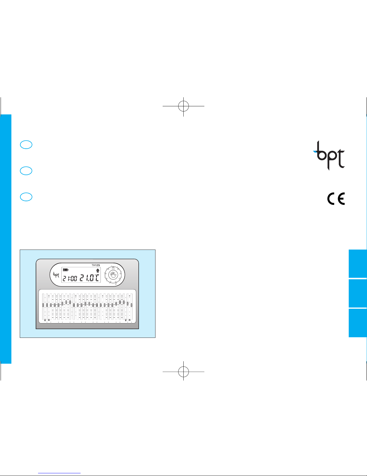
Bpt TH 125 User manual

+15
P
R
21
18
15
12
9
630
°C
24
22
20
18
15
6
°C
28
26
24
22
18
24
22
20
18
15
6
28
26
24
22
18
24
22
20
18
15
6
28
26
24
22
18
°C
24
22
20
18
15
6
°C
28
26
24
22
18
24
618
15
22
18
24
26
20
22
28
GBDF
INSTRUCTIONS
FOR USE
GEBRAUCHS-
ANWEISUNG
MODE
D’EMPLOI
PROGRAMMABLE
THERMOSTAT
THERMOPROGRAM
PROGRAMMIERBARER
RAUMTHERMOSTAT
THERMOPROGRAM
THERMOSTAT
PROGRAMMABLE
THERMOPROGRAM
GB
F
D
TH125
TH125_ITF 24081800 01_07 15-01-2007 16:23 Pagina 1

2
GB
THERMOPROGRAM
TH125
The TH125 THERMOPROGRAM program-
mable thermostat is designed to ensure ideal
temperature conditions at all hours of the
day.
It takes only minutes to install, because it is
connected to the heating/cooling plant sim-
ply by means of two wires.
Three LR03 1.5 V penlight AAA alkaline bat-
teries are used to power THERMOPRO-
GRAM for over one year.
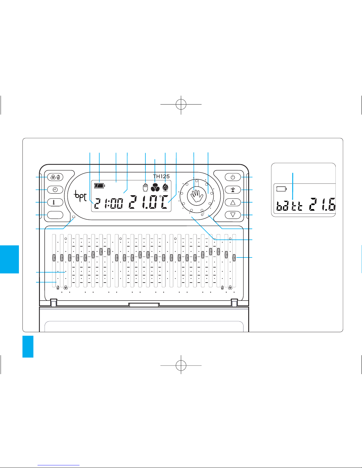
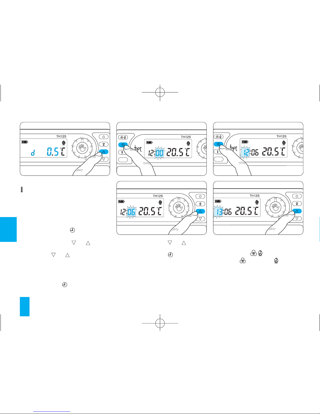
The termostat is extremely easy to program
by means of cursors; a spacious display
enables you to see the time, room tempera-
ture and all the settings.
The temperature threshold can be set at ±0.1
°C or ±0.9 °C.
The THERMOPROGRAM can generally con-
trol both heating and cooling plants and it
can replace any previous on/off thermostat.
Congratulations on your purchase of the
TH125 thermostat.
To get the most out of your thermostat,
exploiting its features and functions to the
full, we suggest you read this manual care-
fully and keep it handy for future reference.
RECOMMENDATIONS
FOR THE INSTALLER
• Read the contents of the following pages
with care because they provide important
information and advice concerning the safe
use, installation and maintenance of the
thermostat.
• When you remove the packaging, make
sure that the thermostat is good order.
• The plant must be in compliance with cur-
rent standards safety.
• The manufacturer cannot be held liable for
any damage due to improper, erroneous or
unreasonable use of the device.
• For any repairs, only call in an after sales
service authorized by the manufacturer.
• Failure to comply with the above recom-
mendations may prejudice the safety of the
device.
TH125_ITF 24081800 01_07 15-01-2007 16:23 Pagina 2

3
GB
DISPOSAL
Do not litter the environment with packing
material: make sure it is disposed of accord-
ing to the regulations in force in the country
where the product is used.
When the equipment reaches the end of its
life cycle, take measures to ensure it is not
discarded in the environment.
The equipment must be disposed of in com-
pliance with the regulations in force, recy-
cling its component parts wherever possi-
ble.
Components that qualify as recyclable waste
feature the relevant symbol and the materi-
al’s abbreviation.
TH125_ITF 24081800 01_07 15-01-2007 16:23 Pagina 3

4
GB
810
9
11
12 13
67
23
24
21
22
1
2
3
4
5
19
20
18
17
14 15
25
OFF
+15 +30 +45
P
R
21
18
15
12
9
630
°C
24
22
20
18
15
6
°C
28
26
24
22
18
24
22
20
18
15
6
28
26
24
22
18
24
22
20
18
15
6
28
26
24
22
18
°C
24
22
20
18
15
6
°C
28
26
24
22
18
24
618
15
22
18
24
26
20
22
28
16
Fig. 1
TH125_ITF 24081800 01_07 15-01-2007 16:23 Pagina 4

5
GB
INDICATIONS AND CONTROLS
(see fig. 1)
1 Sensor push button for cover
closing.
2RReset.
3 Button for viewing the
programmed temperature and
temperature threshold.
4 Push button for clock setting
and for on-off time delays.
5 Button for selecting the cooling
( ) or heating program ( ).
6 Digital clock.
7 Battery charge status.
8OFF Stand-by mode indicator.
9 Display of on-off time delays.
10 MANUAL mode indicator.
P
11 Cooling program indicator.
12 Heating program indicator.
13 Digital thermometer.
14 Button for selecting MANUAL
or AUTOMATIC thermostat
mode.
15 Knob for manual temperature
adjustment.
When the knob is turned, the
temperature field of the
display shows the set tempe-
rature for 4 s.
16 When this warning appears, it
means the batteries are low
.
17 Button for disabling ther-
mostat control, either with or
without anti-freeze protection.
18 Push button for activation
TIMED MANUAL PROGRAM
or STAND-BY MODE.
19 Increase (temperature, day,
time, etc.).
20 Decrease (temperature, day,
time, etc.).
216÷24°C Temperature range for heating
( ) program in MANUAL
operation.
2218÷31°C Temperature range for cooling
( ) program in MANUAL
operation. A position which
exceeds 31 °C (O) places the
system in OFF status.
23 Cursors for temperature
setting in AUTOMATIC mode
for each hour of the day.
When the cursor is moved, in
the hours field the hour that
corresponds to the cursor is
displayed, while the
temperature field shows the
set temperature for 4 s.
246÷24°C Temperature range for heating
program ( ).
0÷23
TH125_ITF 24081800 01_07 15-01-2007 16:23 Pagina 5

6
GB
2518÷31°C Temperature range for heating
program ( ).
A position which exceeds 31
°C (O) places the system in
OFF status.
13 -Viewing the programmed
temperatures 15
14 -Setting of on-off time delays 16
15 -Remote control 16
16 -Replacing the batteries 17
17 -Troubleshooting 18
18 -Cover replacement 19
19 -Technical features 19
- General guarantee terms 21
CONTENTS
Chapter Page
1 - Location 7
2 - Installation 7
3 - Power supply 8
4 - Temperature threshold 9
5 - Setting the clock 10
6 - Heating or cooling programs 10
7 - Automatic program 11
8 - Manual program 12
9 - Timed manual program 12
10 -Stand-by mode in
heating program 13
11 -Stand-by mode in
cooling program 14
12 -Timer-controlled plant
stand-by intervals 14
TH125_ITF 24081800 01_07 15-01-2007 16:23 Pagina 6

7
GB
P
1 - LOCATION
Install the unit on an internal wall (fig. 2) in
a position which is suitable for correct mea-
surement of the room temperature, avoiding
installation in niches, behind doors or cur-
tains, or near heat sources.
2 - INSTALLATION
Open the unit by pressing button P (fig. 3)
while at the same time pulling in the direc-
tion of the arrows.
Remove the terminal covers(fig. 4). To
fasten the base to a rectangular recessed
box (fig. 5) use the 2 screws provided.
To install the base in a round box (fig. 6) use
the provided spacer.
To fix the base to the wall (fig. 7) use the
spacer and the two screws with inserts, all
provided.
WARNING. For the unit to work properly, we
recommend you install it on a flat surface,
being careful not to overtighten screws.
WIRING
Wiring will depend on the type of equipment
controlled by the thermostat: refer, therefo-
re, to the diagram in fig. 8 or fig. 9. Refit the
terminal cover.
KEY
Mains power supply wires
L = phase
OK
Fig. 3
Fig. 4
Fig. 5
Fig. 2
TH125_ITF 24081800 01_07 15-01-2007 16:23 Pagina 7

NC
C
NA
12
LN
U1
12
8
GB
LOAD
Fig. 8
LN
U2
M
NC
C
NA
12
Fig. 9
Loads
U1 = burner, circulation pump, solenoid
valve etc.
U2 = motorized valve
3 - POWER SUPPLY
Insert the three AAA 1.5 V LR03 penlight
batteries, new and of the same type, adhe-
ring to the polarity indicated on the bottom
Fig. 6
Fig. 7
N = neutral
Relay contacts
NC= normally closed contact
C= common
NA = normally open contact
Inputs for remote control
1inlet
2inlet
LOAD CLOSED
OPEN
TH125_ITF 24081800 01_07 15-01-2007 16:23 Pagina 8

9
GB
Fig. 10
Fig. 11
24
618
15
22
18
24
26
20
22
28
P
R
618
15
22
18
24
Fig. 12 Fig. 13
of the housing (fig. 10).
WARNING. Inserting the batteries the
wrong way can damage the unit.
If the messages on the display do not
appear within 30 seconds, press the reset
button R (fig. 54).
Close the unit, making sure the fasteners fit in
the relevant slots (fig. 11). Once the batteries
have been inserted, the display comes on,
featuring the indications illustrated in fig. 12.
The unit is now set to operate in automatic
mode and with the heating program ( ).
The room temperature reading and battery
status indicator now appear.
WARNING. Any time the unit cover is ope-
ned, when settings are complete, it is
necessary to close it correctly to avoid
wasteful battery consumption (fig. 60).
4 - THERMAL THRESHOLD
The temperature differential can be set from
±0.1 °C to ±0.9 °C.
THERMOPROGRAM is supplied factory set
for operation with a temperature differential
of ±0.2 °C.
This threshold, which establishes how soon
the thermostat reacts to temperature chan-
ges, is intended for systems with a high
thermal inertia, such as systems with cast-
iron radiators.
If the features of the system require modifi-
cation of this value, proceed as follows:
4.1 - Press the button twice (fig. 13).
The message d 0.2 °C appears on the
display for about 10 s.
4.2 - Press the button (back) or
(forward) (fig. 14) until the desired value is
reached.
P
TH125_ITF 24081800 01_07 15-01-2007 16:23 Pagina 9

10
GB
P
R
618
15
22
18
24
Fig. 15
24
618
15
22
18
24
26
20
22
28
Fig. 16
P
R
618
15
22
18
24
Fig. 17
5.4 - Press the button or (fig. 18),
until the correct hour is reached.
5.5 - Press the button to end the set-
ting procedure (fig. 19).
The colon between the hours and minutes
flashes to confirm the operation is complete.
In any case, if no button is pressed for 10 s,
the unit automatically exits this procedure,
saving the last data set.
6 - HEATING OR COOLING
PROGRAMS
Press the button ( ) (fig. 20) to choose
the cooling ( ) or heating ( ) program.
The corresponding indication will come on.
In the cooling program, the temperature can
be set from 18 °C to 31 °C.
Over 31 °C, the system goes into shutdown
mode, which is indicated by the message
24
618
15
22
18
24
26
20
22
28
Fig. 14
After approximately 10 s, or if you press the
button, the display will show the time
and room temperature again.
Note. When reset button R is pressed, the
temperature differential returns to the ±0.2
°C default setting.
5 - SETTING THE CLOCK
5.1 - Press the button (fig. 15).
The minutes digits flash.
5.2 - Press the button or (fig. 16)
until the correct minutes value is reached.
Each time the or button is pressed,
the digits on the display go up by one. When
you hold this button down, the digits on the
display increase slowly for the first 5 s then
the sequence of digits advances more quickly.
5.3 - Press button (fig.17).
The hour digits flash.
P
24
618
15
22
18
24
26
20
22
28
Fig. 18
TH125_ITF 24081800 01_07 15-01-2007 16:23 Pagina 10

11
GB
OFF in the temperature field. The indication
is animated when the cooling system is
in operation.
In the heating program, the temperature can
be set from 6 °C to 24 °C.
The indication is animated when the hea-
ting system is in operation.
P
R
618
15
22
18
24
Fig. 19
P
R
618
15
22
18
24
Fig. 20
7 - AUTOMATIC PROGRAM
When the machine is started, it sets up in
AUTOMATIC operating mode.
If the unit is in MANUAL operating mode,
press button (fig. 21) to switch over to
AUTOMATIC. Place cursors 0÷23 (fig. 22)
on the temperature desired for each hour of
the day. Whenever a cursor is moved, the
display gives the temperature set by that
cursor and its position (fig. 23).
You can change programming at any time by
simply moving the cursors to the desired
position.
WARNING. Temperature display is possi-
ble only when the cover is open.
Therefore, if you will not be needing to use
the cursors, close the cover to avoid
wasteful battery use.
24
618
15
22
18
24
26
20
22
28
Fig. 21
18
15
12
9
63
°C
28
26
24
22
18
24
22
20
18
15
6
28
26
24
22
18
24
22
20
18
15
6
28
26
24
22
18
Fig. 22
24
618
15
22
18
24
26
20
Fig. 23
24
618
15
22
18
24
26
20
22
28
Fig. 24
TH125_ITF 24081800 01_07 15-01-2007 16:23 Pagina 11

12
GB
Once you have set the desired time, the devi-
ce starts a countdown.
When it reaches zero, the unit switches from
MANUAL to AUTOMATIC mode.
Programming in hours
9.1 - Select MANUAL operating mode and
set the desired temperature with knob (fig.
26).
9.2 - Press the button (fig. 27).
The message h01 comes up on the display
in place of the current time.
9.3 - Press the button or (fig. 28)
until you reach the desired number of hours,
which can range from 1 to 99.
The countdown of the hours also includes
the hour in which programming is carried out
(hence, the remainder of the hour in which
8 - MANUAL PROGRAM
8.1 - To change over from AUTOMATIC to
MANUAL operating mode, press the button
(fig. 24) (the indication on the display
shows the choice you have made).
8.2 - Use the knob (fig. 25) to set the
desired temperature (on a scale of 6÷24 °C
for the heating program and a scale of
18÷31 °C for the cooling programme).
The unit remains in this condition until you
next switch back to AUTOMATIC mode.
9 - TIMED MANUAL PROGRAM
If you want a constant temperature for a few
hours or a few days (for example to maintain
a comfortable temperature for a longer
period of time during unexpected visits) it is
possible to activate the TIMED MANUAL
PROGRAM.
24
618
15
22
18
24
26
20
22
28
Fig. 25
24
618
15
22
18
24
26
20
22
28
Fig. 26
24
618
15
22
18
24
26
20
22
28
Fig. 27
24
618
15
22
18
24
26
20
22
28
Fig. 28
24
618
15
22
18
24
26
20
22
28
Fig. 29
TH125_ITF 24081800 01_07 15-01-2007 16:23 Pagina 12

13
GB
the setting is made counts as a whole hour).
Note. To return to AUTOMATIC mode before
the programmed time is up, press the
button (fig. 29).
Programming in days
9.4 - Select MANUAL operating mode and
set the desired temperature with knob (fig.
30).
9.5 - Press the button twice (fig. 31).
The message d01 comes up on the display
in place of the current time.
9.6 - Press the button or (fig. 32)
until you reach the desired number of days,
which can range from 1 to 99. The count-
down of the days also includes the day on
which programming is carried out (hence,
the remainder of the day in which the setting
is made counts as a whole day).
Note. To return to AUTOMATIC mode before
the programmed time is up, press the
button (fig. 33).
10 - STAND-BY MODE IN HEATING
PROGRAM
System bypass can be set either with or
without antifreeze protection.
This setting is useful during winter cleaning,
24
618
15
22
18
24
26
20
22
28
Fig. 30
24
618
15
22
18
24
26
20
22
28
Fig. 31
24
618
15
22
18
24
26
20
22
28
Fig. 32
24
618
15
22
18
24
26
20
22
28
Fig. 33
OFF
24
618
15
22
18
24
26
20
22
28
OFF
Fig. 34
maintenance work, or when you are away in
summer, etc. The unit works simply as a
clock and room thermometer. With anti-free-
ze protection.
With anti-freeze protection
10.1 - Press the button once (fig. 34).
The message OFF confirms your choice.
The display will show the previously set anti-
TH125_ITF 24081800 01_07 15-01-2007 16:23 Pagina 13

14
GB
11 - STAND-BY MODE IN COOLING
PROGRAM
11.1 - Press the button once (fig. 37).
The message OFF confirms that THERMO-
PROGRAM control of the system is bypas-
sed. For 5 s, the room temperature reading
disappears, replaced by .
11.2 - To restore AUTOMATIC operating
mode, press button .
12 - TIMER-CONTROLLED PLANT
STAND-BY INTERVALS
To bypass the system (either with or without
the anti-freeze protection) for a few hours or
a few days, proceed as follows:
Programming in hours
12.1 - Ensure that the thermostat is set to
system bypass (with or without anti-freeze).
12.2 - Press the button once (fig. 38).
The message h01 comes up on the display
in place of the current time.
For 5 s, the room temperature reading
disappears, replaced by or the anti-
freeze temperature.
12.3 - Press the button or until the
desired number of hours is reached, from 1
to 99 (fig. 39).
freeze temperature, which can be changed
with the or button (fig. 35).
Any temperature can be chosen between 2
°C and 35 °C, and it will be maintained until
further adjustments are made or until a dif-
ferent operating mode is selected. The
default setting is 6 °C.
After about 5 s from the last operation, the
room temperature appears.
Without anti-freeze protection
10.2 - Press the button twice (fig. 36).
The message OFF confirms that THERMO-
PROGRAM control of the system is bypas-
sed.
For 5 s, the room temperature reading
disappears, replaced by .
10.3 - To restore AUTOMATIC operating
mode, press button .
OFF
24
618
15
22
18
24
26
20
22
28
OFF
Fig. 35
OFF
24
618
15
22
18
24
26
20
22
28
OFF
Fig. 36
OFF
24
618
15
22
18
24
26
20
22
28
OFF
Fig. 37
OFF
24
618
15
22
18
24
26
20
22
28
OFF
Fig. 38
TH125_ITF 24081800 01_07 15-01-2007 16:23 Pagina 14

15
GB
The countdown of the hours also includes
the hour in which programming is carried
out (hence, the remainder of the hour in
which the setting is made counts as a whole
hour).
At the end of the countdown, the machine
goes back to AUTOMATIC operating mode.
Note. To return to AUTOMATIC mode before
the programmed time is up, press the .
Programming in days
12.4 - Ensure that the thermostat is set to
system bypass (with or without anti-freeze).
12.5 - Press the button twice (fig. 40).
The message d01 comes up on the display
in place of the current time.
For 5 s, the room temperature reading
disappears, replaced by or the anti-
freeze temperature.
OFF
24
618
15
22
18
24
26
20
22
28
Fig. 39
OFF
24
618
15
22
18
24
26
20
22
28
OFF
Fig. 40
OFF
24
618
15
22
18
24
26
20
22
28
Fig. 41
12.6 - Press the button or until the
desired number of days is reached, from 1
to 99 (fig. 41). The countdown of the days
also includes the day on which program-
ming is carried out (hence, the remainder of
the day in which the setting is made counts
as a whole day). At the end of the count-
down, the machine goes back to AUTOMA-
TIC operating mode.
Note. To return to AUTOMATIC mode before
the programmed time is up, press the .
13 - WIEWING THE PROGRAMMED
TEMPERATURES
13.1 - Press the button (fig. 42).
For 10 s, the display indicates the value of
the temperature set for the hour indicated.
For instance, if the clock gives a time of 11:45
and the relevant cursor (C11) is positioned on
20 °C, the display with read C11 20 °C.
13.2 - Press the button or (fig. 43) to
show the temperature of the other cursors
(only if automatic programme is set).
If the button is pushed when manual opera-
tion or system bypass is engaged, the relati-
ve set temperature will be displayed. Manual
temperature setting is indicated by the mes-
sage C25.
P
P
R
618
15
22
18
24
Fig. 42
TH125_ITF 24081800 01_07 15-01-2007 16:23 Pagina 15

16
GB
rature set for the hour indicated.
14.3 - Press the button or (fig. 45) to
set the hour in which you want to set the
time delay.
14.4 - Press button within 5 s (fig. 46)
to insert time delay of 15, 30, or 45 min, or
to delete the setting you have made.
For example, if you want to have a comfor-
table temperature at 7:00, you can start the
system at 6:30. To do so, place cursor 6 at
the comfortable temperature and set a time
delay of 30 min. The THERMOPROGRAM
will start at 6.30, maintaining until then the
temperature set by cursor 5.
The indication of the inserted delay is shown
in automatic mode during the hour in which
the delay has been programmed.
The time delay can be programmed for seve-
ral different hours during the same day.
15 - REMOTE CONTROL
By connecting a special interface to terminals
1-2 (fig. 8 or 9) it is possible to remotely acti-
vate a special FIXED-TIME MANUAL pro-
gramme which was previously programmed.
When the fixed-time manual program is acti-
vated remotely, if no other operations are
performed, when the program reaches its
14 - SETTING OF SYSTEM ON-OFF
TIME DELAYS
It is possible to delay system start-up and
shutdown 15, 30, or 45 min. To activate this
function, proceed as follows:
14.1 - Ensure you are in AUTOMATIC opera-
ting mode.
14.2 - Press the button (fig. 44).
The display indicates the value of the tempe-
P
24
618
15
22
18
24
26
20
22
28
Fig. 45
P
R
618
15
22
18
24
+30
+30+30
Fig. 46
24
618
15
22
18
24
26
20
22
28
Fig. 47
24
618
15
22
18
24
26
20
22
28
Fig. 43
P
R
618
15
22
18
24
Fig. 44
TH125_ITF 24081800 01_07 15-01-2007 16:23 Pagina 16

17
GB
conclusion THERMOPROGRAM will go back
to the status it was in prior to activation.
To delete remote control of the fixed-time
manual program, press the button .
The default setting for the fixed-time manual
programme is 1 hour at 20 °C.
Note. When the program is activated remo-
tely, the remaining time in the hour or day is
counted as a full hour or day.
24
618
15
22
18
24
26
20
22
28
Fig. 48
24
618
15
22
18
24
26
20
22
28
Fig. 49
24
618
15
22
18
24
26
20
22
28
Fig. 50
24
618
15
22
18
24
26
20
22
28
Fig. 51
Fixed-time manual programming by remo-
te control
15.1 - Ensure you are in MANUAL operating
mode.
15.2 - Set the desired temperature using
knob (fig. 47).
15.3 - Press button once to set the
hours (fig. 48), twice to set the days (fig.
49).
On the display, instead of the current time,
the message h01 will appear if you are set-
ting the hours, or d01 if you are setting the
days.
15.4 - Press button or until you
reach the desired hours (fig. 50) or days (fig.
51) from 1 to 99.
15.5 - To save the set programme as a pro-
gramme which can be remotely activated,
press the button .
16 - REPLACING THE BATTERIES
When the indicator flashes on the
display, it means you have about 1 month to
replace the batteries (fig. 52).
When the indication plus the
symbol appear on the display, the unit is no
longer operative and has set the heating and
air-conditioning system to OFF (fig. 53).
24
618
15
22
18
24
26
20
22
28
Fig. 52
TH125_ITF 24081800 01_07 15-01-2007 16:23 Pagina 17

18
GB
P
Fig. 55 Fig. 56
24
618
15
22
18
24
26
20
22
28
Fig. 53
P
R
618
15
22
18
24
Fig. 54
WARNING. Failure to replace the batteries in
time may cause damage to the heating
system (anti-freeze protection is not ensured).
To replace the batteries, proceed as follows:
16.1 - Press button P on the bottom (fig.
55) and open the unit.
Performing this operation when the battery
low warning is flashing causes all indica-
tions on the display to disappear.
16.2 - Insert three AAA 1.5 V LR03 penlight
batteries, new and of the same type, adhe-
ring to the polarity indicated on the bottom
of the housing (fig. 56).
Attention. Inserting the batteries the wrong
way round can damage the unit.
You have approx. 2 min to replace the bat-
teries, Once the time for battery replace-
ment has elapsed and you have press reset
button R (fig. 54) all settings you have
made are lost. To restart the unit, proceed
as described in chapter 4.
Close the unit, making sure the fasteners fit
in the relevant slots (fig. 57), and after a few
seconds the indications on the display will
re-appear.
If the messages on the display do not
appear within 30 seconds, press the reset
button R (fig. 54).
WARNING. Any time the cover is opened,
make sure to close it correctly (fig. 60) to
avoid wasteful battery use.
17 - TROUBLESHOOTING
In the event the unit malfunctions, press the
reset button R (fig. 54).
This operation causes all settings you
have made to be lost, though they can be
TH125_ITF 24081800 01_07 15-01-2007 16:23 Pagina 18

19
GB
Fig. 57
Fig. 58
Fig. 59
restored following the procedure descri-
bed in chapter 4 and subsequent chap-
ters.
18 - COVER REPLACEMENT
The unit is delivered with 2 covers in diffe-
rent colours which can be used instead of
the one installed based on the room where
the unit is to be used.
To replace the batteries, proceed as follows:
18.1 - Open the cover and remove it as
shown in figure 58.
18.2 - Insert the new cover as shown in
figure 59 and close it properly (fig. 60).
WARNING. Clean the cover only with a soft
cloth dampened with water.
19 - TECHNICAL FEATURES
Unit for domestic and commercial use.
• Independently installed electronic device.
• LCD graphic display.
• Power supply: three penlight AAA 1.5 V
LR03 alkaline batteries.
• Autonomy: over 1 year.
• Battery low warning.
• Time available for battery replacement:
approximately 2 min.
• Relay: max. voltage 250 V, max. current
5A with resistive load (2A with inductive
load).
Type of action: 1 B-U.
• Range of adjustment in heating mode:
from 6 to 24 °C.
• Range of adjustment in cooling mode:
from 18 to 31 °C.
• Three operating modes: MANUAL,
AUTOMATIC, STAND-BY MODE.
• Selectable programs: HEATING,
COOLING.
• Manual operation enabling or system
switch-off controlled by timer, in hours or
days (up to 99).
• Room temperature measuring interval: 15 s.
TH125_ITF 24081800 01_07 15-01-2007 16:23 Pagina 19

20
GB
Fig. 60
• Thermal differential: adjustable from ± 0.1
°C to ± 0.9 °C.
• Reading resolution: 01 °C.
• Displayed field of reading: from 0 °C to
+40 °C.
• Precision: ≤±0,3 °C.
• Class A software.
• Degree of pollution: 2.
• Impulse voltage: 4 kV.
• Maximum temperature of control head:
40 °C.
• Operating temperature: from 0 °C to +40
°C.
• Protection rating: IP30.
• Dimensions: 139x26x94 mm.
TH125_ITF 24081800 01_07 15-01-2007 16:23 Pagina 20
Other manuals for TH 125
1
Table of contents
Languages:
Other Bpt Thermostat manuals