Bpt TH 125 User manual

THERMOPROGRAM
PROGRAMMABLE
THERMOSTAT
TH 125
INSTRUCTIONS FOR USE
+15
P
R
21
18
15
12
9
630
°C
24
22
20
18
15
6
°C
28
26
24
22
18
24
22
20
18
15
6
28
26
24
22
18
24
22
20
18
15
6
28
26
24
22
18
°C
24
22
20
18
15
6
°C
28
26
24
22
18
24
618
15
22
18
24
26
20
22
28
TH125E 24806650 13-03-13
TH125E 24806650 13-03-13.qxd 13-03-2013 12:09 Pagina 1

2
Congratulations on the purchase of this TH125
thermostat.
For best performance and to enable the best use
of this programmable thermostat’s characteristics
and functions please read this manual carefully and
keep it available for future reference.
WARNINGS
FOR THE INSTALLER
• Read the warnings contained herein with care as
they furnish important instructions regarding safe
use, installation and maintenance.
• After removing the packaging check the condi-
tion of the unit.
• The system must be installed in compliance with
current safety standards.
• The manufacturer declines all liability for any
damage as a result of improper, incorrect or unrea-
sonable use.
• Should the unit be in need of repair contact only
a technical support centre authorised by the man-
ufacturer.
• Failure to comply with the above instructions
may compromise the unit’s safety.
TH125E 24806650 13-03-13.qxd 13-03-2013 12:09 Pagina 2

3
THERMOPROGRAM
TH125
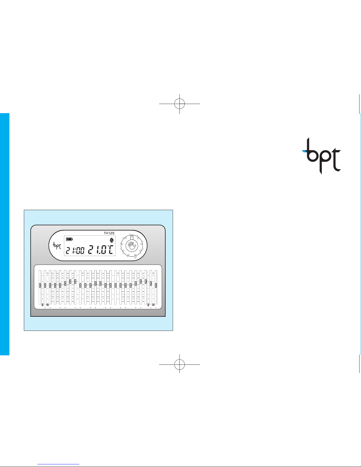
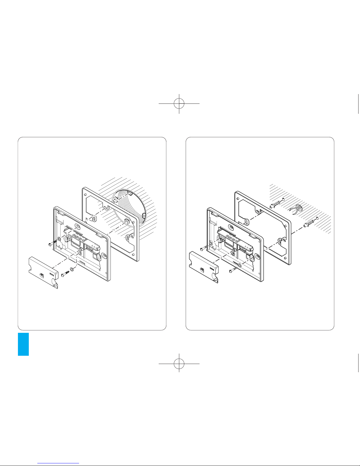
The TH125 THERMOPROGRAM programmable
thermostat has been designed to guarantee ideal
temperature conditions at all times during the day.
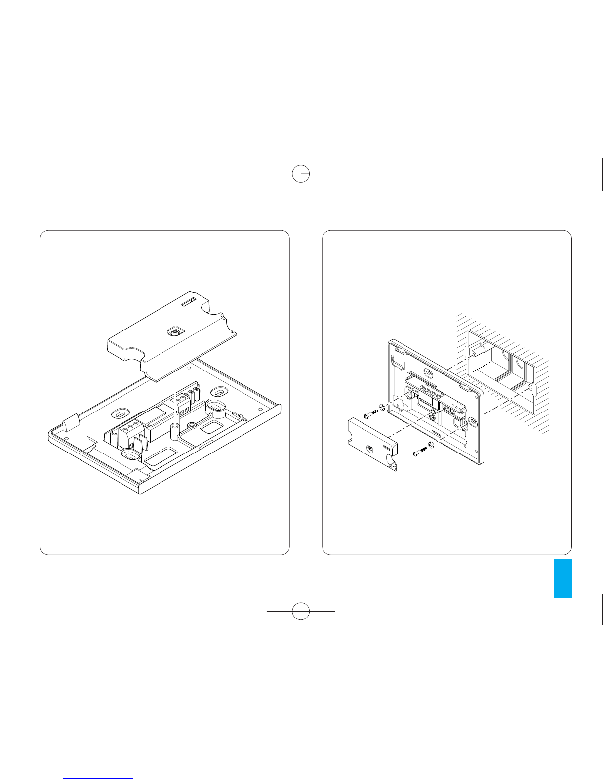
Installation takes only minutes. The thermostat can
be connected to the heating/cooling installation
simply by means of two wires.
Three alkaline LR03 1.5 V penlight AAA batteries
are used to power THERMOPROGRAM for over a
year.
It can be programmed easily using the sliders; the
large display shows the time and ambient temper-
ature together with all programmed data. The ther-
mal differential is adjustable from 0.1°C to 0.9°C
The THERMOPROGRAM can control both heating
and air-conditioning systems, and can be installed
as a replacement for a previous on/off programma-
ble thermostat.
DISPOSAL
Do not litter the environment with packaging mate-
rials: make sure it is disposed of according to the
regulations in force in the country where the prod-
uct is to be used.
When the equipment reaches the end of its life
cycle, avoid discarding it within the environment.
The equipment must be disposed of in compliance
with current regulations, recycling its component
parts wherever possible.
Components that qualify as recyclable waste fea-
ture the relevant symbol and material acronym.
TH125E 24806650 13-03-13.qxd 13-03-2013 12:09 Pagina 3

4
810
9
11
12 13
67
23
24
21
22
1
2
3
4
5
19
20
18
17
14 15
25
OFF
+15 +30 +45
P
R
21
18
15
12
9
630
°C
24
22
20
18
15
6
°C
28
26
24
22
18
24
22
20
18
15
6
28
26
24
22
18
24
22
20
18
15
6
28
26
24
22
18
°C
24
22
20
18
15
6
°C
28
26
24
22
18
24
618
15
22
18
24
26
20
22
28
Fig. 1
16
TH125E 24806650 13-03-13.qxd 13-03-2013 12:09 Pagina 4

5
SYMBOLS AND CONTROLS (fig. 1)
1Door closing sensor button.
2R Reset.
3Display Programmed
Temperature/Thermal Differential
button.
4Setting the clock and the start-up
and shut-down delay period
5Cooling ( ) or heating ( ) pro-
gramme select button.
6Digital clock.
7Battery charge status.
8OFF System bypass symbol.
9Display start-up and shut-down delay
periods.
P
10 MANUAL operating mode symbol.
11 Cooling operating mode symbol.
12 Heating operating mode symbol.
13 Digital thermometer.
14 MANUAL or AUTOMATIC operating
mode select button.
15 Manual temperature adjustment
control
Turning the control causes the
associated temperature to be dis-
played for 4 seconds.
16
When this warning appears, it means
that the batteries are exhausted .
17 System bypass button with or with-
out frost protection.
18 MANUAL TIMED PROGRAMME or
TIMED SYSTEM BYPASS button.
TH125E 24806650 13-03-13.qxd 13-03-2013 12:09 Pagina 5

6
19 Increment (temperature, day, hour,
etc.).
20 Decrement (temperature, day, hour,
etc.).
21 6÷24°C Heating programme temperature
range ( ) in MANUAL operating
mode.
22 18÷31°C Cooling programme temperature
range ( ) in MANUAL operating
mode. A position higher than 31°C
(O) turns the system OFF.
23 Sliders for setting the temperature in
AUTOMATIC operating mode for
every hour of the day.
When the slider is moved the dis-
play reveals the hour corresponding
to that slider and in the temperature
field the relative temperature. This
information is displayed for four sec-
onds.
0÷23
24 6÷24°C Heating programme temperature
range ( ).
25 18÷31°C Cooling programme temperature
range ( ). A position higher than
31°C (O) turns the system OFF.
TH125E 24806650 13-03-13.qxd 13-03-2013 12:09 Pagina 6

7
CONTENTS
Chapter Page
1 - Position 8
2 - Installation 8
3 - Power supply 12
4 - Thermal differential 14
5 - Setting the clock 15
6 - Heating or cooling programme 16
7 - Automatic operation 17
8 - Manual operation 18
9 - Manual timed programme 19
10 - System bypass in heating mode 21
11 - System bypass in cooling mode 23
12 - Temporary system bypass 23
13 - Displaying the
programmed temperatures 25
14 - Setting the system start-up
and shut-down delay period 27
15 - Remote control 28
16 - Battery replacement 29
17 - Thermostat fault condition 33
18 - Door replacement 33
19 -Technical characteristics 35
TH125E 24806650 13-03-13.qxd 13-03-2013 12:09 Pagina 7

8
P
Fig. 3
1 - POSITION
Install the unit on an internal wall (fig. 2) in a posi-
tion which is suitable for correct room temperature
measurement. Avoid installation in niches, behind
doors or curtains, or near heat sources.
2 - INSTALLATION
Open the unit by pressing button P(fig. 3) while at
the same time pulling in the direction of the arrows.
Remove the terminal block cover (fig. 4). Use the
two screws provided (fig. 5) to screw the back of
the unit to a rectangular recessed back-box.
Use the spacer provided (fig. 6) to screw the back
of the unit to a round recessed back-box.
To screw the back of the unit to a wall (fig. 7) use
the spacer, 2 screws and wall plugs provided.
OK
Fig. 2
TH125E 24806650 13-03-13.qxd 13-03-2013 12:09 Pagina 8

9
Fig. 4 Fig. 5
TH125E 24806650 13-03-13.qxd 13-03-2013 12:09 Pagina 9

10
Fig. 6 Fig. 7
TH125E 24806650 13-03-13.qxd 13-03-2013 12:09 Pagina 10

11
NC CNA
12
LN
U1
12
Fig. 8
LOAD
ATTENTION. For the unit to work properly, we rec-
ommend that it should be mounted on a flat surface.
Be careful not to tighten the screws excessively.
ELECTRICAL CONNECTIONS
The wiring will depend on the type of equipment to
be controlled by the thermostat: refer to the dia-
gram in fig. 8 or 9. Refit the terminal block cover.
KEY
Mains power supply wires
L=live
N = neutral
Relay contacts
NC = normally closed contact
C = common
NA = normally open contact
Remote control inputs
1input
2input
TH125E 24806650 13-03-13.qxd 13-03-2013 12:09 Pagina 11

12
LN
U2
M
NC CNA
12
Fig. 9
CLOSE
OPEN
Loads
U1 = burner, circulation pump, solenoid valve, etc.
U2 = motorised valve
3 - POWER SUPPLY
Insert three new alkaline LR03 penlight AAA 1.5V
batteries of the same type. Pay attention to polarity
as shown on the bottom of the housing (fig. 10).
ATTENTION. Inserting the batteries the wrong
way round could damage the unit.
If the symbols on the display do not appear
within 30 seconds, press the reset button R
(fig. 54)
Close the unit making sure that the hooks are
inserted into the slots (fig. 11).
Once the batteries have been inserted the display
comes on featuring the indications illustrated in fig.
12
The unit is now set to operate in automatic heating
mode ().
The room temperature reading and battery status
indicator now appear.
LOAD
TH125E 24806650 13-03-13.qxd 13-03-2013 12:09 Pagina 12

13
Fig. 10 Fig. 11
TH125E 24806650 13-03-13.qxd 13-03-2013 12:09 Pagina 13

14
ATTENTION. Whenever the thermostat door is
opened for making adjustments it is then neces-
sary to close it correctly so as to avoid running
the batteries down unnecessarily (fig. 60).
4 - THERMAL DIFFERENTIAL
The thermal differential is adjustable from 0.1°C to
0.9°C.
THERMOPROGRAM is supplied ready to operate
with a thermal differential of ±0.2°C.
This thermal differential is suitable for systems with
high thermal inertia, for example, installations with
cast aluminium radiators.
If the characteristics of the system make it necessary
to change this value, follow these steps:
Fig. 12
24
618
15
22
18
24
26
20
22
28
Fig. 13
P
R
618
15
22
18
24
Fig. 14
24
618
15
22
18
24
26
20
22
28
TH125E 24806650 13-03-13.qxd 13-03-2013 12:09 Pagina 14

15
4.1 - Press the button twice (fig. 13). d 0.2°C
appears on the display and remains there for 10
seconds.
4.2 - Press the button (backwards) or (for-
wards) (fig. 14) until the desired value is reached.
After around 10 seconds or by pressing button
the display will show the time and ambient temper-
ature.
Note. After a reset the thermal differential is pre-
set to ±0.2°C.
P
P
Fig. 15
P
R
618
15
22
18
24
Fig. 16
24
618
15
22
18
24
26
20
22
28
5 - SETTING THE CLOCK
5.1 - Press button (fig. 15).
The minutes digits flash.
5.2 - Press the or button (fig. 16) until the
desired minutes value is reached.
Every time the or buttons are pressed the
number on the display increments by one.
Pressing the same button down causes the num-
ber on the display to scroll slowly for the first 5 sec-
onds and then progressively more quickly.
5.3 - Press the button (fig.17).
The hour digits flash.
TH125E 24806650 13-03-13.qxd 13-03-2013 12:09 Pagina 15

16
5.4 - Press the or button (fig. 18) until the
desired value is reached.
5.5 - Press button to end the procedure for set-
ting the time (fig. 19).
The colon between the hours and minutes flashes
confirming that the the operation is complete.
If no button is pressed for 10 seconds, the unit
automatically exits this procedure, saving the last
set data.
6 - HEATING OR COOLING PRO-
GRAMME
Press button ( ) (fig. 20) to toggle between cool-
ing ( ) or heating ( ), the corresponding operating
Fig. 18
24
618
15
22
18
24
26
20
22
28
Fig. 19
P
R
618
15
22
18
24
Fig. 17
P
R
618
15
22
18
24
TH125E 24806650 13-03-13.qxd 13-03-2013 12:09 Pagina 16

17
7 - AUTOMATIC OPERATION
At initial switch-on the thermostat starts in AUTO-
MATIC operating mode.
If the thermostat is operating in MANUAL mode
press button (fig. 21) to switch to AUTOMATIC.
Move the sliders 0 ÷ 23 (fig. 22) positioning them in
correspondence with the desired temperature for
each hour of the day.
Each time a slider is moved the display will show the
temperature set by that slider and its position (fig. 23).
Programming can be modified at any time by
simply moving the sliders to the desired position.
mode will be activated. In cooling programme mode
the temperatures that can be selected are in the
range 18°C to 31°C
Selecting a value above 31°C causes the system to
turn off. This will be indicated on the display by the
appearance of the OFF symbol within the temper-
ature field. When operating in cooling mode the
symbol is animated.
In heating programme mode the temperatures that
can be selected are in the range 6°C to 24°C
When operating in heating mode the symbol is
animated.
Fig. 20
P
R
618
15
22
18
24
Fig. 21
24
618
15
22
18
24
26
20
22
28
TH125E 24806650 13-03-13.qxd 13-03-2013 12:09 Pagina 17

18
the temperatures, to avoid running the batter-
ies down unnecessarily, close the door.
8 - MANUAL OPERATION
8.1 - Switch from AUTOMATIC to MANUAL mode by
pressing the button (fig. 24) (the symbol on the dis-
play reflects the selected mode).
8.2 - Rotate the control (fig. 25) to the desired tem-
perature (refer to the 6 ÷ 24°C temperature range for the
heating programme and 18 ÷ 31°C for the cooling pro-
gramme). The thermostat will remain in this operating
mode as and until AUTOMATIC mode is reselected.
ATTENTION. The temperatures are only dis-
played with the door open. When not adjusting
Fig. 24
24
618
15
22
18
24
26
20
22
28
Fig. 23
24
618
15
22
18
24
26
20
22
28
Fig. 22
18
15
12
9
63
C
4
2
0
8
5
6
°C
28
26
24
22
18
24
22
20
18
15
6
28
26
24
22
18
24
22
20
18
15
6
28
26
24
22
18
TH125E 24806650 13-03-13.qxd 13-03-2013 12:09 Pagina 18

19
9 - MANUAL TIMED PROGRAMME
If a fixed temperature is to be maintained for a few
hours or a few days (for example, to maintain a
comfortable temperature for a longer period when
unexpected guests arrive, or when an economical
temperature is required during long periods of
absence), MANUAL TIMED programme mode can
be activated. Once the desired duration has been
set, the device starts a countdown. When it reach-
es zero, the unit switches from MANUAL to AUTO-
MATIC mode, resuming the set programme.
Programming by the hour
9.1 - Select MANUAL operating mode and set the
desired temperature using the rotary control (fig. 26).
9.2 - Press button (fig. 27).
In place of the current time h01 will appear.
9.3 - Press the or buttons (fig. 28) until the
desired number of hours is reached from 1 to 99.
The hours count includes those when program-
ming is performed. The remaining part of the hour
when the operation is performed is therefore
counted as one hour.
Note. To return to AUTOMATIC operating mode
Fig. 25
24
618
15
22
18
24
26
20
22
28
Fig. 26
24
618
15
22
18
24
26
20
22
28
TH125E 24806650 13-03-13.qxd 13-03-2013 12:09 Pagina 19

20
Programming by the day
9.4 - Select MANUAL operating mode and then set
the desired temperature using the rotary control
(fig. 30).
9.5 - Press the button twice (fig. 31).
In place of the current time d01 will appear.
9.6 - Press the or buttons (fig. 32) until the
desired number of days is reached from 1 to 99.
The days count includes those when programming
is performed. The remaining part of the day when
the operation is performed is therefore counted as
one day.
before the programmed period expires press the
button (fig. 29).
Fig. 28
24
618
15
22
18
24
26
20
22
28
Fig. 29
24
618
15
22
18
24
26
20
22
28
Fig. 27
24
618
15
22
18
24
26
20
22
28
TH125E 24806650 13-03-13.qxd 13-03-2013 12:09 Pagina 20
Other manuals for TH 125
1
Table of contents
Other Bpt Thermostat manuals