Bpt TH124.01 User manual

Rh
P
24
20
16
12
8
6
22
26
30
32
34
36 24
20
16
12
8
6
23
22
21
20
19
18
1716
1514
13121110
9
8
7
65432
1
0
22
26
30
32
34
36
24
20
16
12
8
6
24
20
16
12
8
6
PROGRAMMABLE
THERMOSTAT
THERMOPROGRAM
PROGRAMMIERBARER
RAUMTHERMOSTAT
THERMOPROGRAM
THERMOSTAT
PROGRAMMABLE
THERMOPROGRAM
GBD
F
INSTRUCTIONS
FOR USE
GEBRAUCHS-
ANWEISUNG
MODE
D’EMPLOI
TH124.01
GB
F
D
TH/124.02 ITF 2407-9422 01.07 15-01-2007 15:37 Pagina 1

GB
2
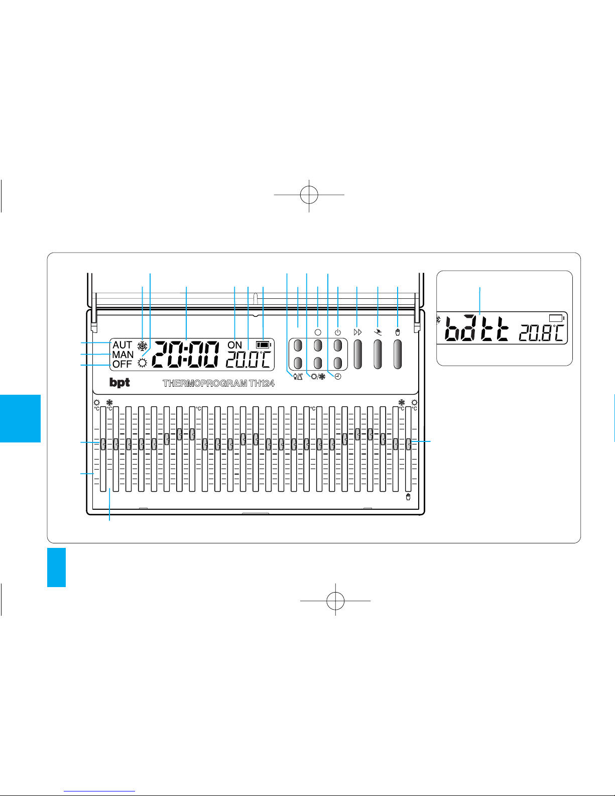
Congratulations on your purchase of the TH124
thermostat.
To get the most out of your thermostat, exploiting
its features and functions to the full, we suggest
you read this manual carefully and keep it handy
for future reference.
RECOMMENDATIONS
FOR THE INSTALLER
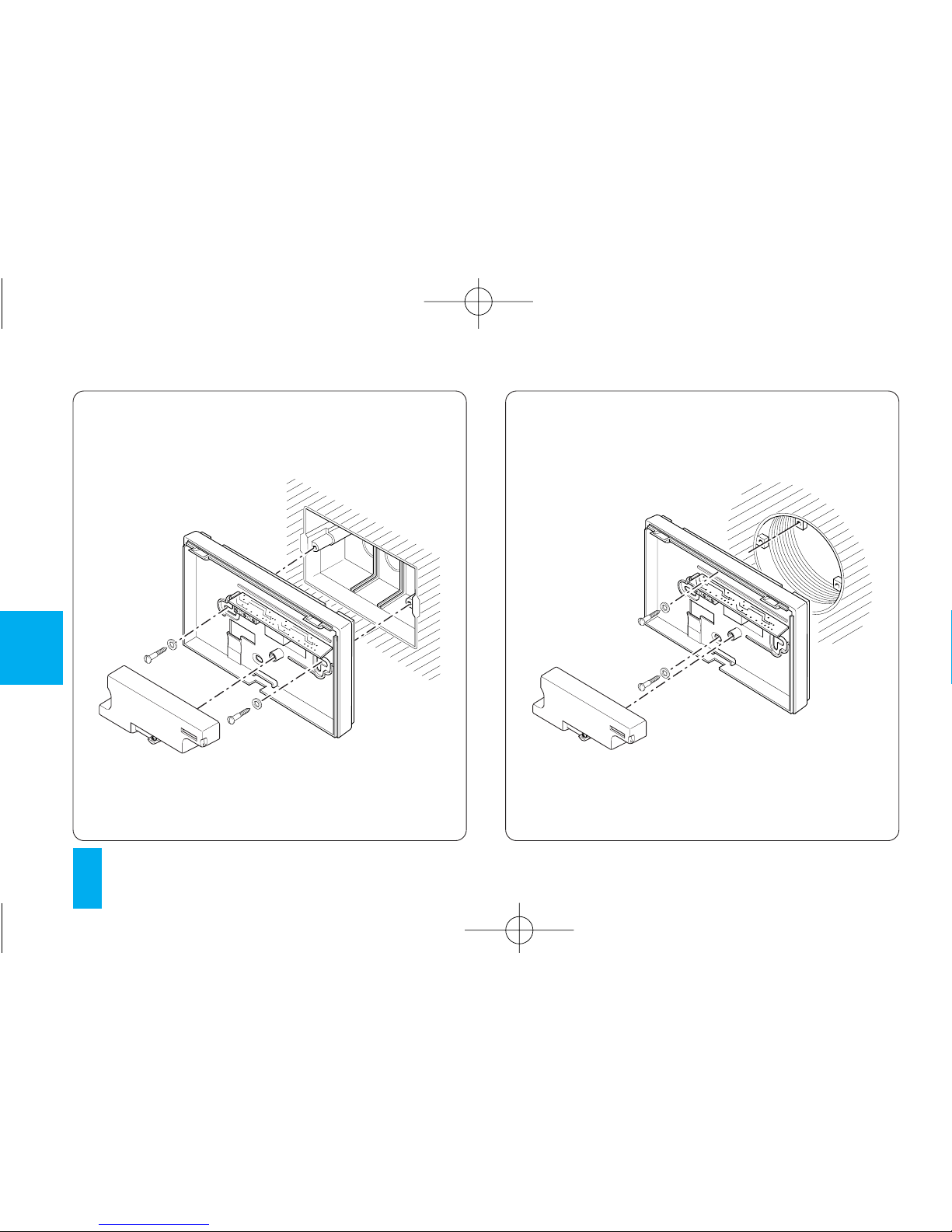
• Read the contents of the following pages with
care because they provide important information
and advice concerning the safe use, installation
and maintenance of the thermostat.
• When you remove the packaging, make sure
that the thermostat is good order.
• The plant must be in compliance with current
standards safety.
• The manufacturer cannot be held liable for any
damage due to improper, erroneous or unreaso-
nable use of the device.
• For any repairs, only call in an after sales ser-
vice authorized by the manufacturer.
• Failure to comply with the above recommen-
dations may prejudice the safety of the device.
TH/124.02 ITF 2407-9422 01.07 15-01-2007 15:37 Pagina 2

3
GB
TH124
THERMOPROGRAM
The TH124 THERMOPROGRAM programmable
thermostat is designed to ensure ideal tempera-
ture conditions at all hours of the day.
It takes only minutes to install, because it is con-
nected to the heating/cooling plant simply by
means of two wires.
Three LR6 type AA 1.5 V alkaline batteries are
used to power the THERMOPROGRAM for over
two year.
The termostat is extremely easy to program by
means of cursors; a spacious display enables
you to see the time, room temperature and all the
settings.
The temperature threshold can be set at ±0.1 °C
or ±0.9 °C.
The THERMOPROGRAM can generally control
both heating and cooling plants and it can repla-
ce any previous on/off thermostat.
TH/124.02 ITF 2407-9422 01.07 15-01-2007 15:37 Pagina 3

GB
4
Rh
P
24
20
16
12
8
6
22
26
30
32
34
36 24
20
16
12
8
6
23
22
21
20
19
18
1716
1514
13121110
9
8
7
65432
1
0
22
26
30
32
34
36
24
20
16
12
8
6
67818 19 20 21
22
11
23
1
2
4914 16
15 17
24
20
16
12
8
6
13
3
5
12
Fig. 1
10
TH/124.02 ITF 2407-9422 01.07 15-01-2007 15:37 Pagina 4

5
GB
KEY TO SYMBOLS
(fig. 1)
1 OFF System OFF indicator.
2 MAN MANUAL mode indicator.
3AUT AUTOMATIC mode indicator.
4Heating program indicator.
5Cooling program indicator.
6Digital clock.
7ON System ON indicator.
8Digital thermometer.
9Battery level.
10 When this warning appears, it
means the batteries are low .
11 6÷24°C Temperature range for heating
program ( ).
12 20÷36°C Temperature range for cooling
program ( ).
CONTROLS
(fig. 1)
13 Button for viewing programmed
temperature and temperature dif-
ferential.
14 R Reset button.
P
TH/124.02 ITF 2407-9422 01.07 15-01-2007 15:37 Pagina 5

GB
6
15 Button for selecting cooling ( ) or
heating program ( ).
16 Button for viewing the system run-
ning time.
17 Clock set button.
18 Button for switching off the system
and for zeroing the counter.
19 Advance button.
20 HOLIDAY PROGRAM selector but-
ton.
21 Button for selecting MANUAL or
AUTOMATIC thermostat mode.
h
22 Cursor for setting temperature in
MANUAL mode.
23 Cursor for setting hourly tempera-
tures in AUTOMATIC mode.
The color of the cursor indicates
the time bans when the
heating/cooling plant operates.
Red = comfort
Blue = energy-saving
0÷23
TH/124.02 ITF 2407-9422 01.07 15-01-2007 15:37 Pagina 6

7
GB
CONTENTS
Chapter Page
1-Location 8
2-Installation 8
3-Power supply 12
4-Temperature threshold 14
5-Setting the clock 15
6-Heating or cooling programs 17
7-Automatic program 17
8-Manual operation 18
9-Holiday program 19
10- Plant running time 21
11- Viewing the programmed
temperatures 22
12- Stand-by mode 23
13- Timer-controlled plant
stand-by intervals 23
14- Replacing the batteries 26
15- Troubleshooting 29
16- Technical features 29
-General guarantee terms 31
TH/124.02 ITF 2407-9422 01.07 15-01-2007 15:37 Pagina 7

OK
GB
8
1 - LOCATION
Install the thermostat on an indoor wall, figure 2,
in a position where it can detect the average
room temperature (avoid placing the thermostat
inside recesses, behind doors or curtains, or
near radiators).
2 - INSTALLATION
Open the thermostat case by pressing button P
(fig. 3), at the same time pulling in the direction
of the arrows.
Remove the terminal cover (fig. 4) and fasten the
back to the wall or on the embedding box using the
P
Fig. 3
Fig. 2
TH/124.02 ITF 2407-9422 01.07 15-01-2007 15:37 Pagina 8

9
GB
Fig. 4 Fig. 5
TH/124.02 ITF 2407-9422 01.07 15-01-2007 15:37 Pagina 9

GB
10
Fig. 6 Fig. 7
TH/124.02 ITF 2407-9422 01.07 15-01-2007 15:37 Pagina 10

11
GB
screws and screw anchors supplied (fig. 5, 6, 7).
WARNING. For the unit to work properly, we
recommend you install it on a flat surface, being
careful not to overtighten screws.
ELECTRIC CONNECTIONS
Wiring will depend on the type of equipment con-
trolled by the thermostat: refer, therefore, to the
diagram in fig. 8 or fig. 9. Refit the terminal cover.
KEY
Mains power supply wires
L= phase
N= neutral
Relay contacts
NA = normally open contact
C= common
NC= normally closed contact
NC
C
NA
LN
U1
Fig. 8
LOAD
TH/124.02 ITF 2407-9422 01.07 15-01-2007 15:37 Pagina 11

GB
12
Loads
U1= burner, circulation pump, solenoid valve etc.
U2= motorized valve
3 - POWER SUPPLY
Insert three LR6 1.5 V penlight AA alkaline batte-
ries, respecting polarity indicated on the bottom
of the housing (fig. 10).
WARNING. Inserting the batteries the wrong
way round can damage the unit.
If the messages on the display do not appear
within 30 seconds, press the reset button R.
Once the batteries have been inserted, the dis-
play comes on, featuring the indications illustra-
ted in fig. 12.
Close the unit, making sure the fasteners fit in the
relevant slots (fig. 11).
The unit is now set to operate in automatic mode
AUT and with the heating program .
NC
C
NA
LN
U2
M
Fig. 9
LOAD
ON
OFF
TH/124.02 ITF 2407-9422 01.07 15-01-2007 15:37 Pagina 12

13
GB
Fig. 10 Fig. 11
TH/124.02 ITF 2407-9422 01.07 15-01-2007 15:37 Pagina 13

GB
14
intended for systems with a high thermal inertia,
such as systems with cast-iron radiators.
Should the features of the system mean this
value must be modified, proceed as follows:
The room temperature reading and battery sta-
tus indicator now appear.
4 - TEMPERATURE THRESHOLD
The temperature differential can be set from ±
0.1 °C to ± 0.9 °C.
THERMOPROGRAM is supplied factory set for
operation with a temperature differential of ± 0.2
°C.
This threshold, which establishes how soon the
thermostat reacts to temperature changes, is
Fig. 12
Rh
P
°C
24
20
°C
24
20
°C
24
20
°C
24
20
Fig. 13
Rh
P
°C
24
20
°C
24
20
°C
24
20
°C
24
20
Fig. 14
h
P
°C
24 °C
24 °C
24 °C
24
R
TH/124.02 ITF 2407-9422 01.07 15-01-2007 15:37 Pagina 14

15
GB
4.1 - Press the button (fig. 13) twice.
The message d 0.2°C appears on the display for
about 10 s.
4.2 - Press button (fig. 14) until you reach the
P
desired value. After approx. 10 s, or if you press
the button, the display will feature the time
and room temperature again.
Note. When reset button R is pressed, the tempera-
ture differential returns to the ± 0.2 °C default setting.
5 - SETTING THE CLOCK
5.1 - Press button (fig. 15).
The minutes digits flash.
5.2 - Press button (fig. 16) until you reach the
exact value of the minutes.
P
Fig. 15
h
P
°C
24 °C
24 °C
24 °C
24
R
Fig. 16
h
P
°C
24
20
°C
24
20
°C
24
20
°C
24
20
R
Fig. 17
h
P
°C
24
20
°C
24
20
°C
24
20
°C
24
20
R
TH/124.02 ITF 2407-9422 01.07 15-01-2007 15:37 Pagina 15

GB
16
hes to confirm the operation is complete.
Whatever the case, if no button is pressed for 10
s, the unit automatically exits this procedure,
saving the last data set.
Every time the button is pressed, the digits
on the display go up by one.
When you hold this button down, the digits on the
display increase slowly for the first 5 s then the
sequence of digits advances more quickly.
5.3 - Press button (fig. 17).
The hour digits flash.
5.4 - Press button (fig. 18) until you reach the
exact hour.
5.5 - Press button to end the setting proce-
dure (fig. 19).
The colon between the hours and minutes flas-
Fig. 18
h
P
°C
24
20
°C
24
20
°C
24
20
°C
24
20
R
Fig. 19
h
P
°C
24
20
°C
24
20
°C
24
20
°C
24
20
R
Fig. 20
h
P
°C
24
20
°C
24
20
°C
24
20
°C
24
20
R
TH/124.02 ITF 2407-9422 01.07 15-01-2007 15:37 Pagina 16

17
GB
6 - HEATING OR
COOLING PROGRAMS
By pressing button (fig. 20), you can select
the cooling program or heating program ,
and the corresponding indicator appears. For
the cooling program, you can set the following
temperatures: from 20 °C to 32 °C, in 1°C steps,
34 °C and 36 °C.
For the heating program, you can set the follo-
wing temperatures: 6 °C, 8 °C and from 12 °C to
24 °C in 1°C steps.
7 - AUTOMATIC PROGRAM
The AUT indicator reports that the unit is in
AUTOMATIC mode. If the unit is in MANUAL
mode, press the button (fig. 21) to switch to
AUTOMATIC mode.
Move the cursors 0÷23 (fig. 22), positioning them
at the desired temperature for each hour of the
day.
Whenever a cursor is moved, the display gives
the temperature set by that cursor and its posi-
tion (fig. 23).
Fig. 21
h
P
°C
24
20
°C
24
20
°C
24
20
°C
24
20
R
Fig. 22
°C
24
20
16
12
8
6
°C
24
20
16
12
8
6
23
22
21
20
19
18
1716
1514
13121110
9
8
7
65432
1
0
°C
24
20
16
12
8
6
°C
24
20
16
12
8
6
TH/124.02 ITF 2407-9422 01.07 15-01-2007 15:37 Pagina 17

GB
18
°C scale for the cooling program). The unit
remains in this condition until you next switch
back to AUTOMATIC mode.
You can change programming at any time by
simply moving the cursors to the desired position.
8 - MANUAL OPERATION
8.1 - To switch from AUTOMATIC mode to
MANUAL mode, press the button (fig. 24) (the
indicator appears on the display to indicate the
selection made).
8.2 - Move the cursor (fig. 25) into line with the
desired temperature (referring to the 6÷24 °C
scale for the heating program and to the 20÷36
Fig. 23
h
P
°C
24 °C
24 °C
24 °C
24
R
Fig. 24
h
P
°C
24
20
°C
24
20
°C
24
20
°C
24
20
R
Fig. 25
°C
24
20
16
12
8
6
23
22
21
20
19
18
1716
1514
13121110
9
8
7
65432
22
26
30
32
34
36
°C
°C
24
20
16
12
8
6
°C
24
20
16
12
8
6
TH/124.02 ITF 2407-9422 01.07 15-01-2007 15:37 Pagina 18

19
GB
9 - HOLIDAY PROGRAM
In the event you want a set temperature for a few
hours or a few days (for example, to maintain a
comfortable temperature for longer when you
have unexpected guests, or when wanting a
frost-protection temperature while you are away
in winter), the HOLIDAY PROGRAM can be
activated in timed MANUAL mode. Once you
have set the desired time, the device starts a
countdown.
When it reaches zero, the unit switches from
MANUAL to AUTOMATIC mode, resuming the
set programme.
Programming in hours
9.1 - Select MANUAL mode and set the desired
temperature (fig. 26).
9.2 - Press button (fig. 27).
The message h01 comes up on the display in
place of the current time.
9.3 - Press the button (fig. 28) until you reach
the desired number of hours, which can range
from 1 to 99.
The countdown of the hours also includes the
Fig. 26
h
P
°C
24
20
°C
24
20
°C
24
20
°C
24
20
R
Fig. 27
h
P
°C
24 °C
24 °C
24 °C
24
R
TH/124.02 ITF 2407-9422 01.07 15-01-2007 15:37 Pagina 19

GB
20
hour in which programming is carried out
(hence, the remainder of the hour in which the
setting is made counts as a whole hour).
Note. To return to AUTOMATIC mode before the
expiry of the programmed interval, press the
button, fig. 29.
Programming in days
9.4 - Select MANUAL mode and set the desired
temperature (fig. 30).
9.5 - Press the button (fig. 31) twice.
The message d01 comes up on the display in
place of the current time.
9.6 - Press the button (fig. 32) until you reach
the desired number of days, which can range
from 1 to 99.
Fig. 28
h
P
°C
24
20
°C
24
20
°C
24
20
°C
24
20
R
Fig. 29
h
P
°C
24
20
°C
24
20
°C
24
20
°C
24
20
R
Fig. 30
h
P
°C
24
20
°C
24
20
°C
24
20
°C
24
20
R
TH/124.02 ITF 2407-9422 01.07 15-01-2007 15:37 Pagina 20
Table of contents
Languages:
Other Bpt Thermostat manuals
Popular Thermostat manuals by other brands

Honeywell
Honeywell AQUASTAT L6188A reference guide

Source 1
Source 1 S1-THSU301-S Owner's Manual & Installation Instructions

Venstar
Venstar T4950-IAQ Owner's manual and installation instructions

Honeywell
Honeywell T8611C owner's manual

flamco
flamco MeiTronic RCD2 manual

Schluter Systems
Schluter Systems DH E RT2 / BW manual