PR electronic 4104 User manual

PERFORMANCE
MADE
SMARTER
Product manual
4104
Universal uni-/bipolar
signal transmitter
TEMPERATURE | I.S. INTERFACES | COMMUNICATION INTERFACES | MULTIFUNCTIONAL | ISOLATION | DISPLAY
No. 4104V102-UK
From serial no.: 121479001

Communication
Display
I.S. Interface
Isolation
Multifunction
Temperature
6 Product Pillars
to meet your every need
With our innovative, patented technologies, we make signal conditioning smarter and simpler. Our portfolio is composed of six
product areas, where we offer a wide range of analog and digital devices covering over a thousand applications in industrial
and factory automation. All our products comply with or surpass the highest industry standards, ensuring reliability in even
the harshest of environments and have a 5-year warranty for greater peace of mind.
Individually outstanding, unrivalled in combination
Our range of temperature transmitters and sensors provides the highest level of signal integrity from the
measurement point to your control system. You can convert industrial process temperature signals to analog, bus or
digital communications using a highly reliable point-to-point solution with a fast response time, automatic self-
calibration, sensor error detection, low drift, and top EMC performance in any environment.
Our unique range of single devices covering multiple applications is easily deployable as your site standard. Having
one variant that applies to a broad range of applications can reduce your installation time and training, and greatly
simplify spare parts management at your facilities. Our devices are designed for long-term signal accuracy, low
power consumption, immunity to electrical noise and simple programming.
We provide inexpensive, easy-to-use, future-ready communication interfaces that can access your PR installed base
of products. All the interfaces are detachable, have a built-in display for readout of process values and diagnostics,
and can be configured via push-buttons. Product specific functionality includes communication via Modbus and
Bluetooth and remote access using our PR Process Supervisor (PPS) application, available for iOS and Android.
Our display range is characterized by its flexibility and stability. The devices meet nearly every demand for display
readout of process signals, and have universal input and power supply capabilities. They provide a real-time
measurement of your process value no matter the industry, and are engineered to provide a user-friendly and
reliable relay of information, even in demanding environments.
We deliver the safest signals by validating our products against the toughest safety standards. Through our
commitment to innovation, we have made pioneering achievements in developing I.S. interfaces with SIL 2 Full
Assessment that are both efficient and cost-effective. Our comprehensive range of analog and digital intrinsically
safe isolation barriers offers multifunctional inputs and outputs, making PR an easy-to-implement site standard.
Our backplanes further simplify large installations and provide seamless integration to standard DCS systems.
Our compact, fast, high-quality 6 mm isolators are based on microprocessor technology to provide exceptional
performance and EMC-immunity for dedicated applications at a very low total cost of ownership. They can be
stacked both vertically and horizontally with no air gap separation between units required.

4104V102-UK 3
Universal uni-/bipolar
signal transmitter
4104
Table of contents
Warning ................................................................................................ 4
Symbol identification .................................................................................... 4
Safety instructions ...................................................................................... 5
How to demount system 4000 ........................................................................... 6
When front LED flashes red or 45xx display shows AO.ER .................................................. 6
Application ............................................................................................. 7
Mounting / installation / programming .................................................................... 7
Applications ............................................................................................ 8
PR 45xx display / programming front ..................................................................... 9
Mounting / demounting the PR 45xx ..................................................................... 9
Order ................................................................................................... 10
Accessories ............................................................................................. 10
Electrical specifications .................................................................................. 10
45xx display readout of input 4...20 mA loop error detection and signal ”outside range” ...................... 13
Connections ............................................................................................ 14
Block diagram ........................................................................................... 15
Configuration / operating the function keys ............................................................... 16
Routing diagram ........................................................................................ 18
Routing diagram, advanced settings (ADV.SET) ............................................................ 20
Help text overview ...................................................................................... 22
Document history ....................................................................................... 23

4 4104V102-UK
Warning
This device is designed for connection to hazardous electric voltages. Ignoring this warning can result in
severe personal injury or mechanical damage.
To avoid the risk of electric shock and fire, the safety instructions of this guide must be observed and
the guidelines followed. The specifications must not be exceeded, and the device must only be applied
as described in the following.
Prior to the commissioning of the device, this installation guide must be examined carefully.
Only qualified personnel (technicians) should install this device. If the equipment is used in a manner not
specified by the manufacturer, the protection provided by the equipment may be impaired.
Warning
Until the device is fixed, do not connect hazardous voltages to the device. The following operations
should only be carried out on a disconnected device and under ESD safe conditions:
General mounting, connection and disconnection of wires.
Troubleshooting the device.
Repair of the device and replacement of circuit breakers must be done by PR electronics A/S only.
Warning
Do not open the front plate of the device as this will cause damage to the connector for the display /
programming front PR 45xx.
This device contains no DIP-switches or jumpers.
SYSTEM 4000 must be mounted on a DIN rail according to DIN EN 60715.
Symbol identification
Triangle with an exclamation mark: Warning / demand. Potentially lethal situations. Read the manual
before installation and commissioning of the device in order to avoid incidents that could lead to
personal injury or mechanical damage.
The CE mark proves the compliance of the device with the essential requirements of the directives.
The double insulation symbol shows that the device is protected by double or reinforced insulation.
GENERAL
HAZARD-
OUS
VOLTAGE
CAUTION

4104V102-UK 5
Safety instructions
Definitions
Hazardous voltages have been defined as the ranges: 75 to 1500 Volt DC, and 50 to 1000 Volt AC.
Technicians are qualified persons educated or trained to mount, operate, and also trouble-shoot technically correct and in
accordance with safety regulations.
Operators, being familiar with the contents of this manual, adjust and operate the knobs or potentiometers during normal
operation.
Receipt and unpacking
Unpack the device without damaging it and check whether the device type corresponds to the one ordered. The packing
should always follow the device until this has been permanently mounted.
Environment
Avoid direct sun light, dust, high temperatures, mechanical vibrations and shock, and rain and heavy moisture. If necessary,
heating in excess of the stated limits for ambient temperatures should be avoided by way of ventilation.
Installation Category II, Pollution Degree 2, and Insulation Class II.
The module is designed to be safe at least under an altitude up to 2 000 m.
Mounting
Only technicians, who are familiar with the technical terms, warnings, and instructions in the manual and who are able to
follow these, should connect the device. Should there be any doubt as to the correct handling of the device, please contact
your local distributor or, alternatively,
PR electronics A/S
www.prelectronics.com
Mounting and connection of the device should comply with national legislation for mounting of electric materials, i.e. wire
cross section, protective fuse, and location.
Descriptions of input / output and supply connections are shown in the block diagram and side label.
The following apply to fixed hazardous voltages-connected devices:
The max. size of the protective fuse is 10 A and, together with a power switch, it should be easily accessible and close
to the device. The power switch should be marked with a label indicating that it will switch off the voltage
to the device.
Year of manufacture can be taken from the first two digits in the serial number.
UL installation requirements
Use 60/75°C copper conducters only
For use only in pollution degree 2 or better
Max. ambient temperature . . . . . . . . . . . . . . . . . . . . . . . . . . . . . . 60°C
Max. wire size. . . . . . . . . . . . . . . . . . . . . . . . . . . . . . . . . . . . . . AWG 26-14
UL file number . . . . . . . . . . . . . . . . . . . . . . . . . . . . . . . . . . . . . E248256
Calibration and adjustment
During calibration and adjustment, the measuring and connection of external voltages must be carried out according to the
specifications of this manual. The technician must use tools and instruments that are safe to use.
Normal operation
Operators are only allowed to adjust and operate devices that are safely fixed in panels, etc., thus avoiding the danger of
personal injury and damage. This means there is no electrical shock hazard, and the device is easily accessible.
Cleaning
When disconnected, the device may be cleaned with a cloth moistened with distilled water.
Liability
To the extent the instructions in this manual are not strictly observed, the customer cannot advance a demand against PR
electronics A/S that would otherwise exist according to the concluded sales agreement.

6 4104V102-UK
How to demount system 4000
Picture 1:
The device is detached from the DIN rail by moving the bottom lock down.
When front LED flashes red or 45xx display shows AO.ER
The 4104 is designed with a high safety level. Therefore, the device continuously measures the output current. If "S4-20" is
selected during configuration, and output current drops to 0 mA, the 45xx display will indicate "AO.ER" and the front LED will
turn red. (A 0 mA output can be caused by an open output loop). The error mode can be reset by power cycling the device or
stepping through the menu.

4104V102-UK 7
Universal uni-/bipolar signal transmitter
4104
• Measures and outputs uni-/bipolar voltage and current signals
• Works with both passive and active inputs and outputs
• Uses the 45xx display for programming and process monitoring
• Fast < 20 mS response time and excellent < 0.05% accuracy
• Universally powered by 21.6…253 VAC / 19.2...300 VDC
Application
• Fast < 20 ms response time for measuring signals produced by torque, position, current & acceleration sensors.
• User configurable bipolar or unipolar I/O means the 4104 is suitable for nearly any voltage or current conversion.
• The excitation source enables measurement of two or three wire transmitters.
• The active or passive I/O makes the 4104 perfect for power matching current loops.
• Converts narrow bipolar inputs to wide bipolar or unipolar outputs, e.g., ± 1 volt input = ± 10 volt or 4-20 mA output.
• Selectable direct or inverse I/O makes the 4104 suitable for proportional control applications.
• The ”V-curve” function outputs 100% – 0 – 100% when a 0 – 100% input signal is present.
Technical characteristics
• The latest analog and digital techniques are used to obtain maximum accuracy and immunity to interference.
• The current output can drive up to 800 Ohms, with an adjustable response time of 0.0…60.0 seconds.
• Exceptional mA output load stability of < 0.001% of span/100 Ohm.
• Meets the NAMUR NE21 recommendations, ensuring high accuracy in harsh EMC environments.
• Meets the NAMUR NE43 recommendations, allowing the control system to easily detect a sensor error.
• Each unit is tested to a high 2.3 kVAC, 3-port galvanic isolation level.
• Excellent signal to noise ratio of > 60 dB.
Mounting / installation / programming
• Very low power consumption means units can be mounted side by side without an air gap – even at 60°C ambient
temperature.
• Approved for marine applications.
• Configuration, monitoring, 2-point process calibration and more are accomplished using PR's 45xx detachable displays.
• All programming can be password protected.
33
32
31
12
14
13
11
(±)
}
10 V
1 V
+
+
10 V
1 V
+
+
(±)
+
(±)
+
+44
43
42
41
+
8 4104V102-UK
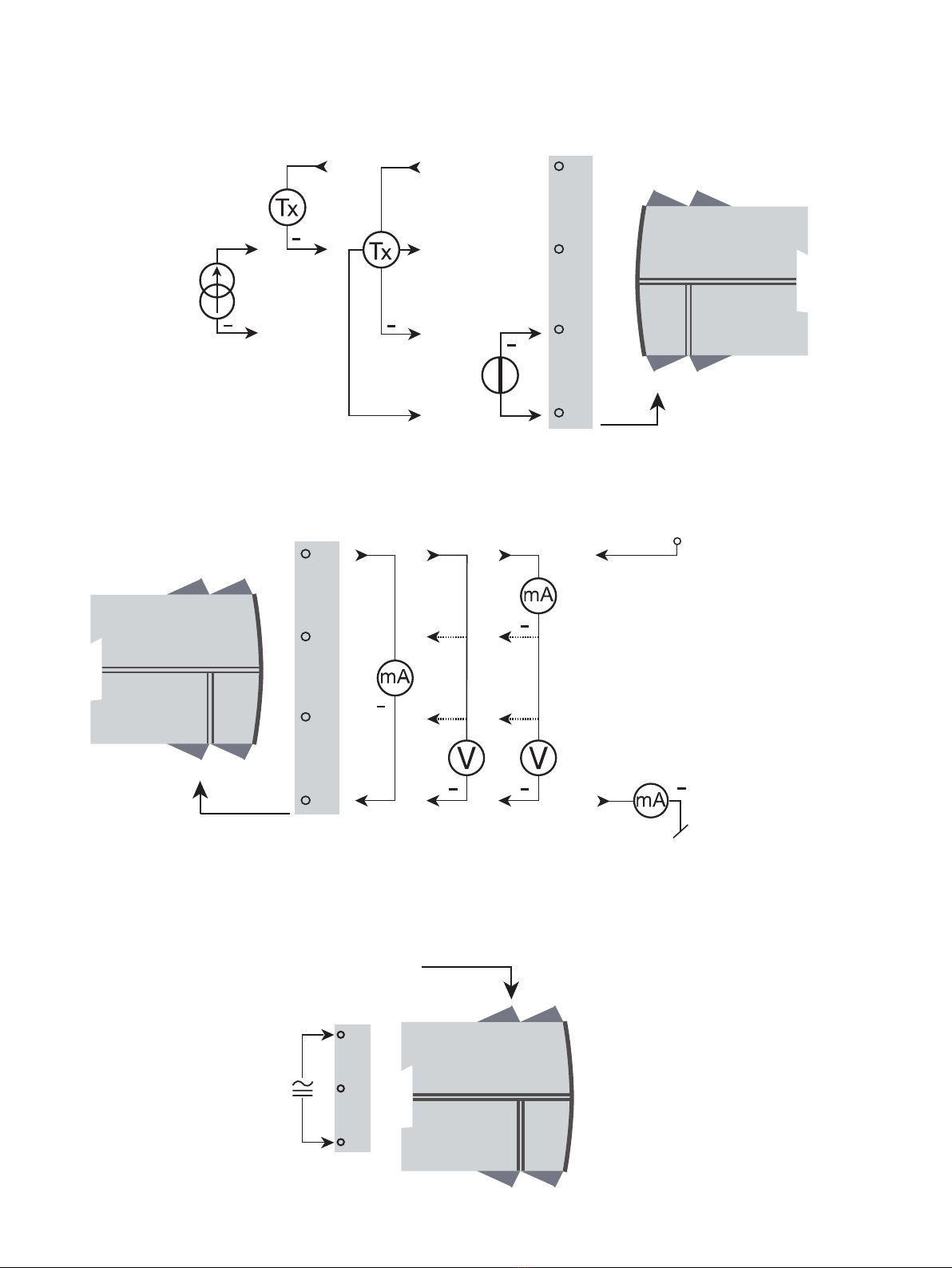
Applications
+ V supply
Power connection:
21.6...253 VAC
or
19.2...300 VDC
Output signals:
Current & voltage 2-wire
Current 3-wire Tx2-wire Tx Voltage
Input signals:
(Current)
(Voltage)

OK
4501
1
3
4
2
3
4
4104V102-UK 9
PR 45xx display / programming front
Functionality
The simple and easily understandable menu structure and the explanatory help texts guide you
effortlessly and automatically through the configuration steps, thus making the product very easy to
use. Functions and configuration options are described in the section ”Configuration / operating the
function keys”.
Application
• Communications interface for modification of operational parameters in 4104.
• Can be moved from one 4104 device to another and download the configuration of the first unit to
subsequent units.
• When mounted in the process, the display shows process values and device status.
Technical characteristics
• LCD display with 4 lines:
Line 1 (H=5.57 mm) shows the scaled process value - OK or error.
Line 2 (H=3.33 mm) shows the selected engineering unit.
Line 3 (H=3.33 mm) shows analog output or TAG no.
Line 4 shows status for communication and signal trending.
• Programming access can be blocked by assigning a password. The password is saved in the device
in order to ensure a high degree of protection against unauthorized modifications to the
configuration.
Mounting / demounting the PR 45xx
1: Insert the tabs of the PR 45xx into the holes at the top of the device.
2: Hinge the PR 45xx down until it snaps into place.
Demounting of the PR 45xx
3: Push the release button on the bottom of the PR 45xx and hinge the the PR 45xx out and up.
4: With the PR 45xx hinged up, remove from holes at the top of the device.

10 4104V102-UK
Order
4104 = Universal uni-/bipolar signal transmitter
Accessories
4501 = Display / programming front
4511 = Modbus communication enabler
4512 = Bluetooth communication enabler
Electrical specifications
Environmental conditions
Operating temperature . . . . . . . . . . . . . . . . . . . . . . . . . . . . . . . . -20°C to +60°C
Storage temperature . . . . . . . . . . . . . . . . . . . . . . . . . . . . . . . . . -20°C to +85°C
Calibration temperature. . . . . . . . . . . . . . . . . . . . . . . . . . . . . . . . 20...28°C
Relative humidity . . . . . . . . . . . . . . . . . . . . . . . . . . . . . . . . . . . < 95% RH (non-cond.)
Protection degree . . . . . . . . . . . . . . . . . . . . . . . . . . . . . . . . . . . IP20
Installation in pollution degree 2 & measurement / overvoltage category II.
Mechanical specifications
Dimensions (HxWxD) . . . . . . . . . . . . . . . . . . . . . . . . . . . . . . . . . 109 x 23.5 x 104 mm
Dimensions (HxWxD) w/ 4501 / 451x . . . . . . . . . . . . . . . . . . . . . . . 109 x 23.5 x 116 / 131 mm
Weight approx. . . . . . . . . . . . . . . . . . . . . . . . . . . . . . . . . . . . . . 155 g
Weight incl. 4501 / 451x (approx.) . . . . . . . . . . . . . . . . . . . . . . . . . 170 g / 185 g
DIN rail type. . . . . . . . . . . . . . . . . . . . . . . . . . . . . . . . . . . . . . . DIN EN 60715 - 35 mm
Wire size . . . . . . . . . . . . . . . . . . . . . . . . . . . . . . . . . . . . . . . . . 0.13...2.08 mm2/ AWG 26...14 stranded wire
Screw terminal torque. . . . . . . . . . . . . . . . . . . . . . . . . . . . . . . . . 0.5 Nm
Vibration. . . . . . . . . . . . . . . . . . . . . . . . . . . . . . . . . . . . . . . . . IEC 60068-2-6
2...13.2 Hz . . . . . . . . . . . . . . . . . . . . . . . . . . . . . . . . . . . . . . ±1 mm
13.2...100 Hz . . . . . . . . . . . . . . . . . . . . . . . . . . . . . . . . . . . . . ±0.7 g
Common electrical specifications
Supply voltage, universal . . . . . . . . . . . . . . . . . . . . . . . . . . . . . . . 21.6...253 VAC, 50...60 Hz
or 19.2...300 VDC
Max. required power. . . . . . . . . . . . . . . . . . . . . . . . . . . . . . . . . . ≤ 2.5 W
Max. power dissipation . . . . . . . . . . . . . . . . . . . . . . . . . . . . . . . . ≤ 2.5 W
Isolation voltage - test / working . . . . . . . . . . . . . . . . . . . . . . . . . . 2.3 kVAC / 250 VAC
Programming . . . . . . . . . . . . . . . . . . . . . . . . . . . . . . . . . . . . . . PR 45xx
Signal dynamics, input / output . . . . . . . . . . . . . . . . . . . . . . . . . . . 20 bit / 18 bit
Signal / noise ratio . . . . . . . . . . . . . . . . . . . . . . . . . . . . . . . . . . . > 60 dB
Bandwidth (3 dB) . . . . . . . . . . . . . . . . . . . . . . . . . . . . . . . . . . . > 40 Hz
Response time (0...90%, 100...10%) . . . . . . . . . . . . . . . . . . . . . . . . < 20 ms
Auxiliary supplies
2-wire loop supply (terminal 43, 44). . . . . . . . . . . . . . . . . . . . . . . . > 16 V @ 20 mA
3-wire loop supply (terminal 42, 44) . . . . . . . . . . . . . . . . . . . . . . . . > 18 V @ 20 mA
Loop supply limitation (terminal 44, nom.). . . . . . . . . . . . . . . . . . . . . 30 mA
of span = of selected range
EMC - immunity influence. . . . . . . . . . . . . . . . . . . . . . . . . < ±0.5% of span
Extended EMC immunity:
NAMUR NE 21, A criterion, burst . . . . . . . . . . . . . . . . . . . . < ±1% of span
Accuracy values
Input type Absolute accuracy Temperature coecient
All ≤ ±0.05% of span ≤ ±0.01% of span / °C

4104V102-UK 11
Input specifications
Current input
Signal range. . . . . . . . . . . . . . . . . . . . . . . . . . . . . . . . . . . . . . . ±23 mA
Programmable measurement ranges . . . . . . . . . . . . . . . . . . . . . . . . 0...20, 4...20, ±10, ±20 mA
Input voltage drop, nom. . . . . . . . . . . . . . . . . . . . . . . . . . . . . . . . 1.4 V @ 20 mA
Loop error detection, 4...20 mA:
Low detection . . . . . . . . . . . . . . . . . . . . . . . . . . . . . . . . . . . . < 3.6 mA
High detection . . . . . . . . . . . . . . . . . . . . . . . . . . . . . . . . . . . . > 21 mA
Voltage input
Signal range. . . . . . . . . . . . . . . . . . . . . . . . . . . . . . . . . . . . . . . ±12 VDC
Programmable measurement ranges . . . . . . . . . . . . . . . . . . . . . . . . 0...1, 0.2...1, 0...5, 1...5, 0...10, 2...10 V,
±1, ±5 and ±10V
Input resistance, nom.. . . . . . . . . . . . . . . . . . . . . . . . . . . . . . . . . 2 MΩ
Current output specifications
Active unipolar and bipolar mA
Programmable ranges . . . . . . . . . . . . . . . . . . . . . . . . . . . . . . . . . 0-20, 4-20, ±10 and ±20 mA
Direct or Inverted action
V-curve function, 100-0-100% . . . . . . . . . . . . . . . . . . . . . . . . . . . 20-0-20 mA
Load, max.. . . . . . . . . . . . . . . . . . . . . . . . . . . . . . . . . . . . . . . . 800 Ω
Passive 2-wire mA
Programmable ranges . . . . . . . . . . . . . . . . . . . . . . . . . . . . . . . . . 0...20 and 4...20 mA
Direct or Inverted action
V-curve function, 100-0-100% . . . . . . . . . . . . . . . . . . . . . . . . . . . 20-0-20 mA
External 2-wire loop supply . . . . . . . . . . . . . . . . . . . . . . . . . . . . . 3.5...26 V
Common specifications current output
Signal range. . . . . . . . . . . . . . . . . . . . . . . . . . . . . . . . . . . . . . . 0...23 mA (unipolar) / -23...+23 mA (bipolar)
Current limit. . . . . . . . . . . . . . . . . . . . . . . . . . . . . . . . . . . . . . . ≤ 28 mA (unipolar) / ±28 mA (bipolar)
Load stability . . . . . . . . . . . . . . . . . . . . . . . . . . . . . . . . . . . . . . ≤ 0.001% of span / 100 Ω
Response time, programmable. . . . . . . . . . . . . . . . . . . . . . . . . . . . 0.0...60.0 s
Output limitation at outside range:
on 4...20 and 20...4 mA signals . . . . . . . . . . . . . . . . . . . . . . . . . . 3.8...20.5 mA
on other unipolar signals . . . . . . . . . . . . . . . . . . . . . . . . . . . . . . 0 and 115% of max. value
on bipolar signals . . . . . . . . . . . . . . . . . . . . . . . . . . . . . . . . . . ±115% of min. and max. values
Sensor error indication, at 4...20 mA input:
selectable . . . . . . . . . . . . . . . . . . . . . . . . . . . . . . . . . . . . . . . Low, High, Zero or None
Low - corresponds to 0 mA at 0...20 mA and to 3.5 mA at 4...20 mA
High - corresponds to 23 mA at both 0...20 and 4...20 mA
Zero - equals 0 mA output
None - the output state is undefined
Voltage output specifications
Programmable ranges . . . . . . . . . . . . . . . . . . . . . . . . . . . . . . . . . 0/0.2...1, 0/1...5, 0/2...10, ±1, ±5 and ±10 V
Direct or Inverted action
V-curve function, 100-0-100% . . . . . . . . . . . . . . . . . . . . . . . . . . . 1-0-1 V, 5-0-5 V and 10-0-10 V
Load, min. . . . . . . . . . . . . . . . . . . . . . . . . . . . . . . . . . . . . . . . . > 500 kΩ
Response time, programmable. . . . . . . . . . . . . . . . . . . . . . . . . . . . 0.0...60.0 s
Output limitation at outside range:
on unipolar signals starting from 0 . . . . . . . . . . . . . . . . . . . . . . . . 0 and 115% of max. value
on unipolar signals with oset . . . . . . . . . . . . . . . . . . . . . . . . . . -5% of min. value and 115% of max. value
on bipolar signals . . . . . . . . . . . . . . . . . . . . . . . . . . . . . . . . . . ±115% of min. and max. values
Sensor error indication, at 4...20 mA input:
selectable . . . . . . . . . . . . . . . . . . . . . . . . . . . . . . . . . . . . . . . Low, High, Zero or None
Low - corresponds to the selected min range value
High - corresponds to the selected max range value
Zero - equals 0 V output
None - the output state is undefined

12 4104V102-UK
Observed authority requirements
EMC. . . . . . . . . . . . . . . . . . . . . . . . . . . . . . . . . . . . . . . . . . . . 2014/30/EU
LVD . . . . . . . . . . . . . . . . . . . . . . . . . . . . . . . . . . . . . . . . . . . . 2014/35/EU
RoHS . . . . . . . . . . . . . . . . . . . . . . . . . . . . . . . . . . . . . . . . . . . 2011/65/EU
EAC . . . . . . . . . . . . . . . . . . . . . . . . . . . . . . . . . . . . . . . . . . . . TR-CU 020/2011
Approvals
c UL us, UL 61010-1. . . . . . . . . . . . . . . . . . . . . . . . . . . . . . . . . . E248256
FM . . . . . . . . . . . . . . . . . . . . . . . . . . . . . . . . . . . . . . . . . . . . 3025177
DNV-GL . . . . . . . . . . . . . . . . . . . . . . . . . . . . . . . . . . . . . . . . . TAA0000101

4104V102-UK 13
45xx display readout of input 4...20 mA loop error detection
and signal ”outside range”
Input loop error check:
Device: Configuration Input loop error detection
4104 OUT.ERR=NONE. OFF
OUT.ERR=DOWN, UP and ZERO ON
Input ”outside range” limits - readout (IN.LO, IN.HI):
Input Range Readout Limit
CURR All - unipolar and bipolar IN.LO < -23 mA
IN.HI > 23 mA
VOLT All - unipolar and bipolar IN.LO < -12 V
IN.HI > 12 V
Display readout below min. / above max. (-1999, 9999):
Input Range Readout Limit
All All -1999 Display readout <-1999
9999 Display readout >9999
Input loop error detection - readout (LO.ER):
Input Range Readout Limit
CURR 4...20 mA LO.ER <= 3.6 mA; > = 21 mA
Readout at hardware error
Error search Readout Cause
Check measurement of analog output AO.ER No load on the current output (only S4...20 mA)*
Communications test between 45xx
and 4104 NO.CO Connection error
Hardware error FL.ER Error in FLASH**
Configuration error CO.ER Error in FLASH**
Check that saved configuration in 45xx
matches device TY.ER Invalid type or rev. no.
Hardware error AO.SU Analog output supply error*
Hardware error RA.ER RAM error*
Hardware error EE.ER EEPROM error*
Hardware error AD.ER A/D converter error*
Hardware error IF.ER Flash check sum error*
!
All error indications in the display flash once per second. The help text explains the error. If the error is an
input loop error, the display backlight flashes as well - this is acknowledged (stopped) by pushing the 3
button.
*Error is acknowledged by either stepping through the basic setup, or by resetting the device power.
Some types of errors can only be acknowledged by resetting the device power.
** Error is acknowledged by stepping through the basic setup.

14 4104V102-UK
Connections
11 1312 14
11 1312 14
+
-mA
11 1312 14
+
mA
11 1312 14
41 4342 4441 4342 44 41 4342 44
31 32 33
41 4342 44
+
-
+ -
(±)
(±) -(±)
(±)
Tx +- Tx +-
V+-
(±)
V+-
(±)
41 4342 44
Tx +-
Outputs:
2-wire transmitterCurrent Voltage, 10 VVoltage, 1 V
Current
Inputs:
Voltage
Supply
3-wire voltage
transmitter
3-wire current
transmitter2-wire transmitter

4104V102-UK 15
Block diagram
500Ω
EEPROM
D / A
11
13
14
50Ω
33
31
12
PTC
43
44
42
41
20 Ω
A/D
V
V
mA
mA
I+
10 V
1 V
4104
I + V I V
HW
Watchdog
CPU
mA -
+
-
+
-
-
+
+
-
21.6...253 VAC or
19.2...300 VDC
+Vsupply
2-wire
Green
Red
Gnd.
3-wire
transmitter
2-wire
transmitter
(Voltage)
(Current)
Voltage
Current

16 4104V102-UK
Configuration / operating the function keys
Documentation for routing diagram.
In general
When configuring the 4104, you will be guided through all parameters and you can choose the settings which fit the
application. For each menu there is a scrolling help text which is automatically shown in line 3 on the display.
Configuration is carried out by use of the 3 function keys:
1will increase the numerical value or choose the next parameter
2will decrease the numerical value or choose the previous parameter
3will save the chosen value and proceed to the next menu
When configuration is completed, the display will return to the default state 1.0. Pressing and holding 3will return to the
previous menu or return to the default state (1.0) without saving the changed values or parameters.
If no key is activated for 1 minute, the display will return to the default state (1.0) without saving the changed values or
parameters.
Further explanations
Password protection: Programming access can be blocked by assigning a password. The password is saved in the device in
order to ensure a high degree of protection against unauthorised modifications to the configuration. If the configured
password is not known, please contact PR electronics support - www.prelectronics.com/contact.
Signal and loop error info via display front 45xx
Input loop error at 4-20 mA signal is displayed as LO.ER (see table page 13). Input signals outside the selected range are
displayed as IN.LO indicating low input signal or IN.HI indicating high input signal (see table page 13). Error indication is
displayed in line 1 as text and at the same time the backlight flashes. A flashing bullet in line 4 is indicating correct
functioning of 45xx.
Signal and sensor error indication without display front
Status of the unit can also be read from the red/green LED in the front of the device.
Green flashing LED 13 Hz indicates normal operation.
Green flashing LED 1 Hz indicates loop error.
Steady green LED indicates internal error.
Steady red LED indicates fatal error.
Advanced functions
The unit gives access to a number of advanced functions which can be reached by answering “Yes” to the point “ADV.SET”.
Memory (MEM): In the memory menu you can save the configuration of the device in the 45xx, and then move the 45xx onto
another device of the same type and download the configuration in the new device.
Display setup (DISP): Here you can adjust the brightness contrast and the backlight. Setup of TAG numbers with 6
alphanumerics. Selection of functional readout in line 3 of the display - choose between readout of analog output or tag no.
Two-point process calibration (CAL): The device can be process-calibrated in 2 points to fit a given input signal . A low input
signal (not necessarily 0%) is applied and the actual value is entered via 45xx. Then a high signal (not necessarily 100%) is
applied and the actual value is entered via 45xx. If you accept to use the calibration, the device will work according to this
new adjustment. If you later reject this menu point or choose another type of input signal the device will return to factory
calibration.
Process simulation function (SIM): In the menu point “EN.SIM” it is possible to simulate an input signal by means of the arrow
keys and thus control the output signal up or down. You must exit the menu by pressing 3(no time-out).
The simulation function exits automatically, if the 45xx is detached.
Password (PASS): Here you can choose a password between 0000 and 9999 in order to protect the unit against
unauthorised modifications to the configuration. The unit is delivered default without password.

4104V102-UK 17
Language (LANG): In the menu ”LANG” you can choose between 7 different language versions of help texts that will appear
in the menu. You can choose between UK, DE, FR, IT, ES, SE and DK.
Output function (OFUN): Here the output characteristics can be set to either Direct (DIR) or Inverted (INV) function. Output
type and range are set in the normal programming menu. If the selected output range is starting at zero, V-curved output
function (VFUN) can also be selected. The output characteristics will then be 100-0-100% on the basis of a linear 0-100%
input signal.
Auto diagnostics
The device performs an advanced auto diagnosis of the internal circuits - check tables on page 13.

33
0000
PASSW.
Txt 1
0000
9999
NO
ADV.SET
Txt 2
NO
YES
1 21 2
*1
10.4 mA
%
40.0
YES
ADV.SET
Txt 2
NO
YES
1 2
CURR
IN TYPE
Txt 3
VOLT
CURR
1 2
33
3
3
3
*0
4-20
I.RANGE
Txt 4
-/+20
-/+10
0-20
4-20
1 2
3
0-10
V.RANGE
Txt 5
1 2
12
VO LT
CURR
3
-/+10
-/+5
-/+1
2-10
0-10
1-5
0-5
0.2-1
0-1
@C
@F
%
A
bar
cm
ft
ft/h
ft/min
ft/s
g
gal/h
gal/min
GW
hp
hPa
Hz
in
in/h
in/min
in/s
ips
K
kA
kg
kJ
kPa
kV
kW
kWh
l
l/h
l/min
l/s
m
m/h
m/min
m/s
m/s2
m3
m3/h
m3/min
mA
mbar
mils
min
mm
mm/s
mol
Mpa
mV
MW
MWh
N
Ohm
Pa
pH
rpm
s
S
t
t/h
uA
um
uS
V
W
Wh
yd
[blank]
UNIT
mA
Txt 6
[blank]
:
:
%
@F
@C
(69 units)
1 2
11.11
DEC.P
Txt 7
111.1
11.11
1.111
1111
1 2
VOLT
IN TYPE
Txt 3
3
18 4104V102-UK
Routing diagram
If no key is activated for 1 minute, the display will return to the default state 1.0 without saving configuration changes.
1Increase value / choose next parameter
2Decrease value / choose previous parameter
3Save the chosen value and proceed to the next menu
Hold 3Back to previous menu / return to menu 1.0 without saving.
Continued on the page
Routing diagram ADV.SET
*0 Default state.
Line 1 shows the scaled process value - OK or error.
Line 2 shows the selected engineering unit.
Line 3 shows analogue output or TAG no.
Line 4 shows status for communication and signal trending.
*1 Only displayed if password is enabled.
Power up
1and 2held:
Toggle line 3 function
A.Out / TAG.
(Setting is volatile - use
DISP setup menu to
change and store line 3
function).
Correct No
Yes
Correct No
Yes
Selectable UNITS:
Continued on
the next page

0.00
DISP.LO
Txt 8
99.99
-19.99
1 2
10.00
DISP.HI
Txt 9
99.99
-19.99
1 2
33 CURR
ANA.OUT
Txt 10
CURR
VOLT
1 2
3ACTI
OUT.MOD
Txt 13
PASS
ACTI
1 2
4-20
O.RANGE
Txt 11
1 2
*3
-/+20
-/+10
S4-20
4-20
0-20
CURR 33
3UP
OUT.ERR
Txt 14
NONE
UP
ZERO
DOWN
1 2
0.0
RESP.
Txt 15
60.0
0.0
1 2
*2 *4
0-10
O.RANGE
Txt 12
1 2
-/+10
-/+5
-/+1
2-10
0-10
1-5
0-5
0.2-1
0-1
VOLT
ANA.OUT
Txt 10
33
VO LT
4104V102-UK 19
To default state 1.0
*2 Menu not displayed if a Bipolar Output Range is selected.
*3 Direct or Inverted output characteristics must be set in the
ADV setting OFUN menu.
Only ranges starting at zero are available for OFUN = V.FUNC
- refer to *6.
*4 Menu only displayed if input type supports sensor error
check.

CAL
SETUP
Txt 16/3
SIM
SETUP
Txt 16/4
3
DISP
SETUP
Txt 16/2
3
CONTRA
Txt 18
9
0
1 2
TT0123
TAGNO_
Txt 20
0-9
A-Z
1 2
9
LIGHT
Txt 19
9
0
1 2
A.OUT
LINE 3
Txt 21
TAG
A.OUT
1 2
3 3 333
MEM, DISP,
CAL, SIM,
PASS, LANG,
OFUN
1 2
MEM
SETUP
Txt 16/1
SAVE
MEMORY
Txt 17
SAVE
LOAD
1 2
33
PASS
SETUP
Txt 16/5
NO
EN.PASS
Txt 29
YES
NO
1 2
0000
NEW.PAS
Txt 30
9999
0
1 2
333
YES
CAL.LO
Txt 22
YES
NO
1 2
NO
CAL.HI
Txt 24
YES
NO
1 2
0.00
V
Txt 23
10.00
0.00
1 2
NO
USE.CAL
Txt 26
YES
NO
1 2
8.00
V
Txt 25
10.00
0.00
1 2
3 3 333 3
NO
ENA.SIM
Txt 27
YES
NO
1 2
35.0
V
Txt 28
10.00
0.00
1 2
3
*5
*5
*5
NO NO
NO
NO
20 4104V102-UK
Routing diagram, advanced settings (ADV.SET)
To default state
1.0
In the submenu simulation (SIM) you must press 3or
remove the 45xx to return to the default state 1.0.
Continued on
the next page
*5 Selectable range as defined by DEC.P, DISP.LO and DISP.HI.
Table of contents
Popular Transmitter manuals by other brands

IDTOLIGHT
IDTOLIGHT WERCHTER ID836004ZZZ installation instructions

GDD Instrumentation
GDD Instrumentation TxIII instruction manual

EnOcean
EnOcean PTM 230 user manual

Lamtec
Lamtec Lambda LS2-K quick reference

EUTECH INSTRUMENTS
EUTECH INSTRUMENTS 2-WIRE CONDUCTIVITY TRANSMITTER operating instructions

Micatrone
Micatrone Micaflex PD ver 4 Installation & operation manual


