HES OzBlok OBW0545 User manual

OPERATOR’S MANUAL
POWDER COATED CARBON STEEL
& STAINLESS STEEL
BRAKE WINCHES
Working Loads: 270KG. 410KG. 600KG.
Please read the Owner’s Manual
carefully before operating
the equipment. Keep this
manual nearby the
equipment at
all times.
CARBON STEEL:
OBW0545
OBW0820
OBW1200
STAINLESS STEEL:
OSSBW0545
OSSBW0820
OSSBW1200
AS/NZ1418.2
CE
pg.1
Hoisting Equipment
Specialists Pty Ltd
31 Mangrove Lane
Taren Point
NSW 2229 Australia
Phone: 1300 798 464
Fax: 1300 309 041
www.hesnsw.com.au
www.ozblok.com.au

pg.2
Table of Contents
Pg. 3 . . . . . . . . . . . . . . . . . . . . . . . . . Warranty
Pg. 4 . . . . . . . . . . . . . . . . . . . . . . . . . Important Information and Precautions
Pg. 5 . . . . . . . . . . . . . . . . . . . . . . . . . Warnings and Precautions
Pg. 6 . . . . . . . . . . . . . . . . . . . . . . . . . Installing the Winch
Pg. 7 . . . . . . . . . . . . . . . . . . . . . . . . . Installing the Rope
Pg. 8 . . . . . . . . . . . . . . . . . . . . . . . . . Concept of Operation / Pre-Operation
Pg. 9 . . . . . . . . . . . . . . . . . . . . . . . . . Inspection
Pg. 10 . . . . . . . . . . . . . . . . . . . . . . . . Inspection Chart
Pg. 11 . . . . . . . . . . . . . . . . . . . . . . . . Repair of Winch / Trouble Shooting Chart
Pg. 12 . . . . . . . . . . . . . . . . . . . . . . . . Specications / Performance Characteristics
Pg. 13 . . . . . . . . . . . . . . . . . . . . . . . . Mounting
Pg. 14 . . . . . . . . . . . . . . . . . . . . . . . . Parts
Pg. 15 . . . . . . . . . . . . . . . . . . . . . . . . Parts / Service Notes

pg.3
Warranty
All OZBLOK products are guaranteed to be free of defects in materials and workmanship for one year from
the date of shipment.
This does not apply to any product showing signs of misuse, overloading, alteration, improper maintenance
or negligence. Normal wear and tear of moving parts including brake discs, wire rope, and other wear
components are excluded from this warranty. This warranty does not cover any costs involving removal of
this product, lost time, or any other incidental or consequential damages or costs resulting from the claimed
defects.
If any of our products fail during the rst year of operating due to defective materials or workmanship, it will
be repaired or replaced at the discretion of OZBLOK. The product will then be returned to the customer free
of charge. If no defect is found, the customer will be responsible for return shipping costs.
Upon repair, the product will be covered by the warranty for the remainder of the original warranty period.
OZBLOK will not be held liable for injuries to persons or property, death, incidental, consequential, or
contingent damages, whether negligent or deliberate, arising from the use of the product. It is the sole
responsibility of the owner to install and operate the product properly and safely.
This is OZBLOK’s only written warranty. This warranty is in lieu of all other warranties implied by law such
as merchantability and tness. The sale of OZBLOK products under any other warranty or guarantee,
expressed or implied, is not authorized.
Note: OZBLOK has the right to alter the design or discontinue the production of any product without prior
notice.
Warranty Policy
Any product for which there is a warranty claim must be returned prepaid to an authorized OZBLOK
warranty depot along with proof of purchase.
For more information please contact:
Hoisting Equipment
Specialists Pty Ltd
31 Mangrove Lane
Taren Point
NSW 2229 Australia
Phone: 1300 798 464
Fax: 1300 309 041
www.hesnsw.com.au
www.ozblok.com.au

Important Information and Precautions
The information in this manual should be used only for the OZBLOK Brake Winches. This manual contains
general instructions dealing with the normal installation, operation, and maintenance of the products
described herein. The information provided should not be expected to prepare the user for all possible
circumstances.
This product should not be installed, operated, or maintained by any person who has not read all the
contents of these instructions. Failure to read and comply with these instructions, warnings, or limitations
noted might result in bodily injury, death, or property damage. Contact the distributor for further explanation
if information is not fully understood.
It is the responsibility of the owner/user to install, test, maintain, and operate these products in accordance
with OSHA, regulations, other federal, state, and local regulations, and AS/NZ standards.
Only trained and qualied personnel shall operate and maintain this equipment.
Maintain Records
Schedule and maintain records of regular inspection and maintenance of the product in compliance with
AS/NZ standards. Record your Brake Winch serial number and purchase date on the front cover of this
manual to allow for easier referencing.
Precautions
Do not use OZBLOK in conjunction with other equipment unless the system designer, manufacturer,
installer, or user has put the necessary safety devices in place. Modications to upgrade or alter these
products should only be authorized by the original manufacturer.
Brake Winches should be used for holding loads only within their load ratings.
These Brake Winches meet or exceed the following standards:
AS/NZ1418.2
CE
pg.4

pg.5
Warnings and Precautions
Failure to read and comply with the following warnings may result in a hazardous situation that
could lead to death, serious injury, or property damage. Keep this manual near the equipment at
all times. Do not remove, alter, or obscure the labels attached to the winch. Contact OZBLOK for
replacement manuals and labels.
Do Not operate until all personnel are warned or cleared from the area.
Do Not lift people or lift loads over people.
Do Not allow people anywhere near the potential path of wire rope that could snap.
Do Not allow people or situations to become distractions while operating the winch.
Do Not alter the equipment.
Do Not operate a damaged or malfunctioning product.
Do Not leave a suspended load unattended without taking proper precautions.
Do Not operate without verifying wire rope is installed securely to winch drum.
Do Not operate with any power other than manual.
Do Not operate without a minimum of 4 anchor wraps of wire rope on the drum.
Do Not get close to moving parts of the equipment including drum, gears, wire rope.
Do Not lift more than the designated load rating of the winch or other system parts.
Do Not use more than one winch to lift a load, unless the system is so designed.
Do Not lift or pull loads on an incline without a brake installed on the equipment.
Do Not use if the load is not suspended vertically.
Do Not use the equipment if guards are removed or improperly installed.
Do Not allow the load to swing or jerk and avoid shock loads by operating smoothly.
Do Not weld on the lifted load.
Do Not secure load by wrapping wire rope around it, instead use rigging connectors.

pg.6
Installing the Winch
Choosing a location
• Have a qualied professional conrm that the foundation complies with local codes, is rigid and level,
and will support the winch under all load conditions.
• Avoid areas with corrosives, ammables, combustibles, explosives, and other potentially
damaging materials.
• Situate the winch where the operator can avoid the load area and the potential path of snapping
wire rope.
• Situate the winch in a place where it can be seen throughout the whole operation.
• Avoid areas with potential interferences such as trafc and obstacles.
• Ensure the winch is easily accessible for operation and routine maintenance.
Installation
1. Use a eet angle between 0.5 and 1.5 degrees.
• This angle permits the rope to spool more evenly onto the drum, reducing harm to the wire rope.
2. Do Not weld the winch frame to the foundation.
• Doing so would invalidate the warranty.
• Contact OZBLOK for more information.
3. Fasten the winch rmly to the foundation.
• For standard products use M10 coarse thread fasteners of at least grade 8 with a torque of 30 ft. lb.
without lubrication. Use safe engineering practices to assure that the mounting holes are attached rmly to
a solid foundation that will support the winch and load in all situations.
4. Install the Sheave Roller or Roller Guide.
• It is recommended to use a sheave roller or roller guide to direct the wire rope onto the drum.
• Follow recommendations of the sheave manufacturer on installation and use.
• Install sheaves, tracks, and other equipment so that they stay rmly in place in all load situations.
• Select sheaves of a suitable diameter to lessen damage to the wire rope.
Maintain Fleet Angle
1. Wire rope moves over sheave or through the roller guide. Situate sheave or guide an acceptable
distance from the drum (distance “A”)
2. Wire rope moves directly to the load. Use tracks or guide rails to prevent sideway movements that can
stress and harm the drum ange.
0.5 and 1.5 degrees
Load
Tracks or�
guide rails Center line
Smooth drum
0.5 and 1.5 degrees

Installing the Wire Rope
• Ensure the wire rope spools correctly and is attached rmly to the winch drum to prevent release of the load.
• Wear protective clothing when working with the wire rope.
• Prevent damage to the rope by keeping it clean and not allowing it to pass through dirt or debris.
Consider the following information when choosing
the proper wire rope.
• Lay of the rope should match the winding direction of the drum.
• Breaking strength should be at least 3 times greater than the largest load when pulling on a horizontal
surface. 5 times that if loads are lifted or pulled at inclines.
• OZBLOK advises a 7 x 19 galvanized aircraft cable be used for diameters up to 5/16 inch.
• Contact a wire rope supplier for further assistance.
Installation
1. Use a ange clip or quick disconnect anchor to anchor the rope to the drum.
a. Flange Clip Anchor
i. Thread the end of the wire rope through the ange hole.
ii. Connect the carriage bolt and wrap the wire rope around it.
iii. Fit the clip on so that it holds the wire rope with its curves.
iv. Tighten the jam nut on until it attens the wire rope against the drum ange.
b. Quick Disconnect Anchor
i. Insert the End Stop through the center hole in the drum ange.
ii. Pull the wire rope and the end stop into the slot.
2. Spool the rope onto the drum by turning the handle clockwise.
a. If the rope unwinds it needs to be re-installed correctly before continuing.
3. Keep the rope under tension, and using the winch, spool four full wraps of rope onto the drum.
pg.7
Drum End View
Drum End View

Concept of Operation
1. Assure that the total force needed to lift the load does not surpass the load rating of the winch.
2. Follow all recommended maintenance and inspections to monitor for any damage that could contribute
additional weight to the equipment.
3. A disc brake should be used if loads will be lifted or pulled on an incline.
4. Be aware of variables affecting performance ratings of the equipment.
a. Loose spooling and overlapping of the wire rope affects drum capacity. Actual drum capacities are
25-30% less than those listed in performance tables.
b. As rope spools around the drum, the force needed to lift the load increases and the load rating of the
winch decreases.
i. Performance table values are based on a drum without rope and with a maximum handle length.
ii. The load rating is the greatest pull that can be applied on new equipment without damage or other
factors affecting its operation.
5. Maintain the correct eet angle and keep sufcient tension on the rope so it winds evenly.
6. Take in consideration the factors that can affect the duty rating.
a. Equipment Maintenance
i. Perform preventative maintenance and inspections to check for damage or defects on a regular basis.
ii. Keep the winch clean and free of debris.
b. Environmental Conditions
i. Avoid exposure to extreme temperatures, excessive dirt, wet conditions, ammables, combustibles,
explosives, and other potentially damaging materials.
c. Loading Conditions
i. Do not exceed maximum load ratings or shock load.
d. Frequency of Use
i. Monitor the equipment’s parts often as frequency of use increases. More use will increase wear and
shorten the life span of the parts.
Pre-Operation
• Be certain that no hazards will interfere with any part of operation and the load will have adequate clear
space to be moved.
• Complete all recommended inspections and any maintenance that are due.
• Assure that the operator is well rested, has up to date training on the equipment, and has proper personal
protective equipment including hardhat, safety shoes and eyewear, work gloves, and no loose tting
clothing or jewelry.
• Know the total force of the load so that the load rating of the equipment is not surpassed.
pg.8

Inspections
In order to maintain quality operation of the product, a regular inspection schedule should be set up by
each operator. All inspections should be reported and maintained in a dated record log. These records
should be available to all personnel involved with the product, and should be made available to OZBLOK
when a warranty issue is in question.
Denitions
The following denitions will be used in the inspections procedure that follows.
Designated Person- a person who is selected or assigned as being competent to perform specic duties
to which they are assigned.
Qualied Person- a person that by possession of a recognized degree or certicate of professional
standing, or through extensive knowledge, training, and experience, has successfully demonstrated they
are able to resolve problems relating to the subject matter and work.
Normal Service- service that involves operation with randomly distributed loads within the rated load limit,
or uniform loads less than 65% of rated load for not more than 15% of the time.
Heavy Service- service that involves operation within the rated load limit and exceeds normal service.
Severe Service- service that involves normal or heavy service with abnormal operating conditions.
Inspection Classications
Frequent Inspections- The operator or designated person performs frequent inspections by doing a visual
examination and by listening for unusual sounds during operation. These inspections are usually performed
before each operation, every few hours in operation, and if problems arise.
Periodic Inspections- A designated person performs periodic inspections, which are more detailed
inspection, by doing visual examinations of internal and external conditions. These inspections are done on
the following schedule:
*Normal Service- Semi-annually
*Heavy and Severe Service- Quarterly
*Also perform following storage and return to use, if a possible shock load has occurred, and if operation
issues arise.
Label Equipment as “Out of Service” if damaged or maintenance is required
• Discontinue use of wire rope and equipment if damage or overloading occurs.
pg.9

Take note of the following regarding inspections.
• Brakes require more than audible and visual inspection. Check daily by operating with and without a load,
stopping at various positions to ensure safe operation. If the load coasts or creeps contact the factory for
friction disc replacements.
• Proper inspection may require disassembly of some parts. Contact the factory before doing so or the
applicable warranty may be voided.
• For wire rope inspections please contact the specic manufacturer of the rope. The inspection provided in
the chart below is for a general inspection only and is in no way the complete inspection required.
• Before operation assure all deciencies on the inspection chart are resolved and inspections are up to
date. Refer to troubleshooting chart for further assistance.
Inspection Chart
Frequent Inspection (F) and Periodic Inspection (P)
Location Check For F P
General Paint chipping or excessive wear X
Damage, cracks, rust, dents excess wear, or corrosion. X
Unusual sounds X
Smooth load movements X
Winch lubricated X
Signs of overloading (cracks, dents, or damage) X
Proper function when operated with a load equal to the load rating X
Foundation Good condition/Supports the winch under all conditions X
Cracks, corrosion, damage X
Brake Assembly Ratchet pawl clicks rmly as handle is turned clockwise X
Proper operation X
Corrosion, cracks, damage, or wear X
Fasteners Firmly installed X
Properly tightened X
Stripped threads, bent, or damage (check by removing winch from the foundation) X
Gears, bearings, shafts Excess wear, cracks, corrosion, or damage X
Well lubricated X
Handle Rotates freely in both directions X
End Connections Corrosion, excess wear, rust, or damage X
Attached rmly X
Drum Excess wear or distortion of anchor hole X
Excess movement due to misaligned gears, bearings, shafts (check by moving the drum by hand) X
Load Hook Bent, twisted or damaged X
Hook latch doesn’t close when released X
Securely attached to wire rope with no fraying or damage to the rope X
Frame Bent, cracks, or damage (signs of overloading) X
Wire rope Installed correctly X
Wound tightly and evenly on drum X
No visible damage to entire rope X
Labels Not been removed, altered, or obscured (Contact factory for replacements) X
pg.10

Repair of the Winch
All repairs must have factory authorization. Contact OZBLOK to prevent voiding of the warranty and
potential damage to the winch.
Perform recommended inspections to identify which parts should be replaced.
• Only use OZBLOK replacement parts.
• Contact the local OZBLOK dealer for replacement parts. Please have the serial number
and part number and description available when calling.
Protect the winch from damage and corrosion by monitoring for paint chipping or excess wear.
• Renish any problem areas by removing paint to the bare metal, cleaning the area well and repainting
with a high quality primer and nish coat.
Troubleshooting Chart
Contact OZBLOK if disassembly of the winch or brake is required. The warranty will be voided if this is not done.
Problem Possible Cause Correction
Brake distance too long Discs are worn, damaged, or over lubricated Replace
Disc brake ratchet pawl damaged or worn Replace
Excess wear on gears or bearings Overloaded Reduce load
Improper lubrication Relubricate
Drum not turning (handle functioning okay) Damaged or loose spring pins Repair
Gears broke, stripped, or loose Repair/Replace
Difculty turning handle or not turning at all Heavy load Reduce load
Disc brake damaged or locked Repair
Gears or bearings damaged or locked Repair
Spring pins loose or damaged Repair
High pitched squeak Improper lubrication Relubricate
Grinding noise Dirty lubrication Clean and relubricate
Dirty brakes or gears Clean
Broken gears or bearings Replace
Rattling noise Loose bolts, screws, fasteners Tighten
No clicking noise in brake Ratchet not properly installed Install correctly
Ratchet pawl damaged or worn Replace
Uneven brake clicking Broken gear tooth Replace
Dull brake clicking Dirty or damaged spring or ratchet pawl Clean or repair
Excess wear of brake ratchet pawl, spring, or gear Replace
pg.11
pg.12
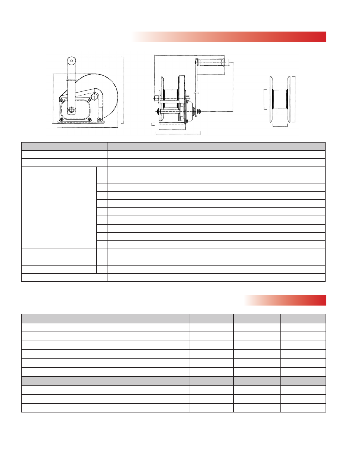
Specications
A
B L
C
M
K
F
E
D
H
I J
G
Performance Characteristics
Model/Wire rope diameter (in.) 1st layer Mid drum Full drum
OBW0545 - OSSBW0545 with 3mm wire rope 2.1 22 42
OBW0545 - OSSBW0545 with 5mm wire rope 1.5 10 22
OBW0820 - OSSBW0820 with 5mm wire rope 2.1 20 42
OBW0820 - OSSBW0820 with 6mm wire rope 1.5 8 27
OBW1200 - OSSBW1200 with 6mm wire rope 2.4 11 26
OBW1200 - OSSBW1200 with 8mm wire rope 2.1 6 16
Load rating
OBW0545 - OSSBW0545 270 200 180
OBW0820 - OSSBW0820 410 300 200
OBW1200 - OSSBW1200 600 410 300
*Actual drum capacities may be 25-30% less, due to nonuniform winding. Wire rope tension will also affect drum capacity.
Model OBW0545 - OSSBW0545 OBW0820 - OSSBW0820 OBW1200 - OSSBW1200
WLL (kg) 270 kg 410 kg 600 kg
Gear Ratio 4.2:1 5:1 10:1
Dimensions (mm) A 158 196 212
B 183 238 282
C 88 107 127
D 210 322 330
E 27 27 27
F 265 270 300
G 50 58 64
H 109 109 109
I 48 60 76
J 135 178 180
K 260 390 390
L 152 175 200
M 3 3.5 4
Net Weight (kg) 4 8 10
pg.13
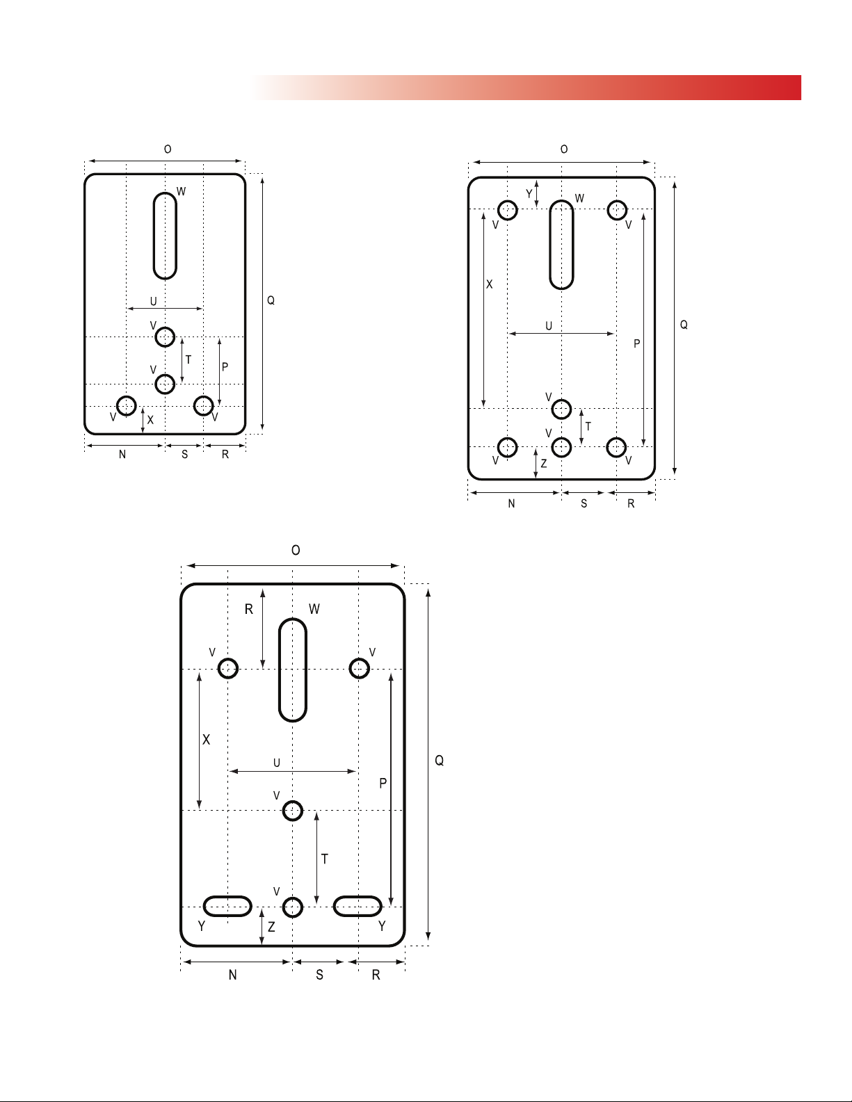
Mounting
OBW0545
OSSBW0545
N= 44
O= 88
P= 33
Q= 138
R= 24
S=20
T= 27
U= 40
V= 10
W= 10 x 42
X= 13
OBW1200
OSSBW1200
N= 64
O= 127
P= 162
Q= 240
R= 49
S= 38
T= 43
U= 76
V= 10
W= 10 x 45
X= 119
Y= 10 x 20
Z= 30
OBW0820
OSSBN0820
N= 53
O= 106
P= 134
Q= 192
R= 18
S= 35
T= 20
U= 70
V= 10
W= 10 x 55
X= 114
Y= 29
Z= 29

pg.14
Parts
1. Nut (1)
2. Screw (1)
3. Drum (1)
4. Cover (1)
5. Mounting Base (1)
6. Snap Ring (2)
7. Ratchet Pawl (2)
8. Retaining Ring (2)
9. Shaft (1)
10. Rachet (1)
1. Nut (1)
2. Screw (1)
3. Drum (1)
4. Cover (1)
5. Mounting Base (1)
6. Snap Ring (2)
7. Ratchet Pawl (1)
8. Retaining Ring (1)
9. Bolt (1)
10. Friction Brake (2)
11. Friction Brake (2)
12. Clip (1)
13. Shaft (1)
14. Cover Part (1)
15. Washer 6 (5)
16. Bolt (5)
17. Nut (1)
18. Washer (1)
19. Support Rod (1)
20. Nut (1)
11. Rachet (1)
12. Clip (1)
13. Shaft (1)
14. Cover Part (1)
15. Washer (4)
16. Bolt (2)
17. Bolt (2)
18. Nut (1)
19. Washer (1)
20. Retaining Ring (2)
21. Retaining Ring (2)
22. Washer (2)
23. Gear (1)
24. Clip (1)
25. Bolt (1)
26. Washer (1)
27. Retaining Ring (1)
28. Handle (1)
29. Washer (1)
30. Nut (1)
40. Wire Rope Clip
21. Washer (2)
22. Nut (2)
23. Gear (1)
24. Clip (1)
25. Washer (1)
26. Retaining Ring (1)
27. Handle (1)
28. Washer (1)
29. Nut (1)
40. Wire Rope Cip (1)
OBW0820 - OSSBW0820
OBW0545 - OSSBW0545

Service Notes
pg.15
Parts
1. Nut (1)
2. Screw (1)
3. Drum (1)
4. Cover (1)
5. Nut (1)
6. Munting Base (1)
7. Snap Ring (2)
8. Ratchet Pawl (2)
9. Retaining Ring (2)
10. Bolt (2)
11. Shaft (1)
12. Rataining Ring (1)
13. Washer (1)
14. Gear (1)
15. Gear (1)
16. Shaft (1)
17. Shaft (1)
18. Cover Part (1)
19. Washer (6)
20. Bolt (3)
21. Washer (1)
22. Retaining Ring (1)
23. Handle (1)
24. Washer (1)
25. Nut (1)
26. Nut (1)
27. Washer (1)
28. Bolt (1)
29. Washer (1)
30. Support Pipe (1)
31. Retaining Ring (2)
32. Washer (2)
33. Support Rod (1)
34. Gear (1)
35. Clip (1)
36. Friction Brake (2)
37. Ratchet (1)
38. Clip (1)
39. Bolt (1)
40. Wire Rope Clip (1)
OBW1200 - OSSBW1200

Hoisting Equipment
Specialists Pty Ltd
31 Mangrove Lane
Taren Point
NSW 2229 Australia
Phone: 1300 798 464
Fax: 1300 309 041
www.hesnsw.com.au
www.ozblok.com.au
This manual suits for next models
5
Table of contents
Other HES Winch manuals


