BRADEN CH330 Manual

1
LIT2718 R2
PB243
April 2017
Printed in USA
©2017 PACCAR Inc.
All rights reserved
WRITE HOIST SERIAL NUMBER BELOW
}
First 2 numbers indicate
year manufactured
For serial number location see page 4
Visit our Web site at www.paccarwinch.com for the most comprehensive collection of winch, hoist, and drive
information on the Internet. Most publications and specification sheets are available for downloading.
CH330 and CH400
HYDRAULIC WINCH
INSTALLATION, MAINTENANCE,
AND SERVICE MANUAL
CH330
CH400

2

3
TABLE OF CONTENTS
Foreword .....................................................................................................................4
Model and Serial Number Location .............................................................................4
Explanation of Model Number .....................................................................................4
General Safety Recommendations..............................................................................5
Theory of Operation.....................................................................................................6
Winch and Wire Rope Installation ...............................................................................8
3-piece Cable Anchor Installation (Model CH400).......................................................9
Hydraulic Circuits.......................................................................................................10
Preventive Maintenance............................................................................................ 11
Weights, Oil Capacities, and Special Tools ...............................................................13
Troubleshooting.........................................................................................................14
Service Precautions...................................................................................................17
Winch Disassembly ...................................................................................................17
Drum Support End Bracket Service...........................................................................18
Exploded-view Drawing.............................................................................................19
Parts List....................................................................................................................20
Winch Drive/Gearbox Service ...................................................................................21
Subassembly Service................................................................................................22
Brake Assembly Service............................................................................................23
Planet Carrier Service ...............................................................................................26
Winch Assembly ........................................................................................................28
Brake Valve Service ..................................................................................................32
Recommended Fastener Torque ...............................................................................35
Metric Conversion Chart............................................................................................36
4
FOREWORD
Read this entire publication and retain it for future reference.
For inquiries regarding your BRADEN hoist or this publication, please contact BRADEN Service Department at 918-
251-8511, Monday through Friday, 8:00 a.m. to 4:30 p.m. (CST).
The minimum service intervals specied are for operating hours of the prime mover.
The following service instructions have been prepared to provide assembly, disassembly, and maintenance informa-
tion for the BRADEN Model CH330/CH400A series winch. It is suggested that before performing any work on these
units, all assembly and disassembly instructions should be read and understood.
Some illustrations in this manual may show details or attachments different from your hoist. Some components have
been removed for illustrative purposes. Drawings in this manual represent a typical unit sold through our distribution
channels. Some hoists, particularly those sold directly to original equipment manufacturers (OEM), may differ in appear-
ance and options.
EXPLANATION OF MODEL NUMBER
CH 330 A 69 120 - 01 - G - 1
CONSTRUCTION
HOIST
MAX
RATING
DESIGN
RATING
GEAR
RATIO
MOTOR
SIZE
DRUM
SIZE
OPTION
CH CONSTRUCTION HOIST
330 33,000-POUND DESIGN FIRST-LAYER LINE PULL
A MODEL SERIES RELATING TO DESIGN CHANGES
69 TOTAL GEAR REDUCTION
120 HYDRAULIC MOTOR DISPLACEMENT IN CU. IN/REV (120 = 12.0 CU. IN REV)
01 DRUM OPTION
G OTHER DRUM OPTIONS (G = GROOVED; M = MACHINED; P = RATCHET AND PAWL
U = UNDERWOUND)
1 PERMITS TESTING AND INSPECTION PER API 2C FOR OFFSHORE CRANES
DRUM
OPTION
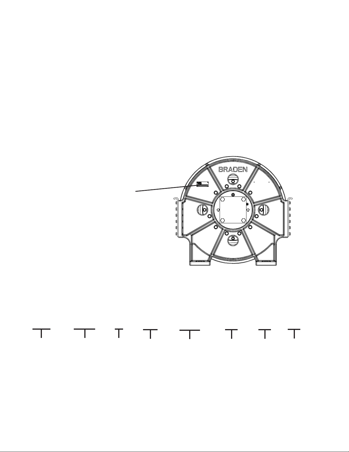
Model numbers and serial numbers are
stamped into the motor end bracket as
shown at right. Always refer to the model
number and serial number when requesting
information or service parts.
5
GENERAL SAFETY RECOMMENDATIONS
Safety for operators and ground personnel is of prime concern. Always take the necessary precautions to ensure safety
to others as well as yourself. To ensure safety, the prime mover and winch must be operated with care and concern by
the operator for the equipment, and a thorough knowledge of the machine’s performance capabilities. The following
recommendations are offered as a general safety guide. Local rules and regulations will also apply.
1. Read all warning tag information and become familiar
with all controls before operating winch.
2. Never attempt to clean, oil or perform any mainte-
nance on a machine with the engine running, unless
instructed to do so in the service manual.
3. Never operate winch controls unless you are properly
seated at the operators station on the prime mover and
you are sure personnel are clear of the work area.
4. Assure that personnel who are responsible for hand
signals are clearly visible and that the signals to be
used are thoroughly understood by everyone.
5. Ground personnel should stay in view of the prime
mover operator and clear of winch drum. Do not al-
low ground personnel near winch line under tension. A
safe distance of at least 1-1/2 times the length of the
cable should be maintained.
6. On machines having hydraulically, mechanically and/
or cable controlled equipment, be certain the equip-
ment is either lowered to the ground or blocked se-
curely before servicing, adjusting and/or repairing the
winch. Always apply the prime mover parking brakes
and lower equipment before dismounting the prime
mover.
7. Inspect rigging, winch and hydraulic hoses at the be-
ginning of each work shift. Defects should be correct-
ed immediately.
8. Keep equipment in good operating condition. Perform
scheduled servicing and adjustments listed in the
Preventive Maintenance section of this manual.
9. An equipment warm-up procedure is recommended
for all start-ups and is essential at ambient tempera-
tures below +40°F (4°C). Refer to “Warm-Up Proce-
dure” listed in the Preventive Maintenance section of
this manual.
10. Be sure of equipment stability before operating winch.
11. The winches described herein are neither designed
nor intended for use or application to equipment used
in the lifting or moving of persons.
12. Do not exceed the maximum pressure (PSI or kPa) or
ow (GPM or LPM) stated in the winch specications.
13. Operate winch line speeds to match job conditions.
14. Leather gloves should be used when handling winch
cable.
15. Never attempt to handle winch cable when the hook
end is not free.
16. When winding winch cable on the winch drum, never
attempt to maintain tension by allowing winch cable
to slip through hands. Always use the hand-over-hand
technique.
17. Never use winch cable with broken strands. Replace
winch cable.
18. Do not weld on any part of the winch.
19. Do not use knots to secure or attach winch cable.
20. Use recommended hydraulic oil and gear lubricant.
21. Keep hydraulic system clean and free from contami-
nation at all times.
22. Use correct size cable anchor for cable and pocket in
winch drum.
23. The BRADEN wire rope anchors are capable of sup-
porting the rated load when installed properly. For ad-
ditional safety, ALWAYS maintain a minimum of ve
wraps of wire rope on the drum.
Safety Informational callouts used in this manual in-
clude the following:
Failure to obey the following safety recommendations may
result in property damage, personal injury, or death.
CAUTION – This emblem warns against potential or
unsafe practices which COULD result in personal in-
jury and product or property damage if proper proce-
dures are not followed.
CAUTION
WARNING – This emblem warns against hazards and
unsafe practices which COULD result in severe per-
sonal injury or death if proper procedures are not fol-
lowed.

6
THEORY OF OPERATION
DESCRIPTION OF WINCH
The winch is made up of the following sub-assemblies and
parts:
1. Hydraulic motor, brake valve and motor adapter
2. Drum and drum support assembly
3. Motor end support
4. Tie plates
5. Brake clutch assembly
6. Drive assembly with multiple disc parking brake and
internal gearing
DUAL BRAKE SYSTEM
DESCRIPTION
The dual brake system consists of a dynamic brake sys-
tem and a static brake system.
The dynamic brake system has two operating compo-
nents:
1. Brake valve assembly
2. Hydraulic motor
The brake valve is basically a counterbalance valve. It
contains a check valve to allow free ow of oil to the motor
in the haul-in direction and a pilot operated, spring load-
ed spool valve that blocks the ow of oil out of the motor
when the control valve is placed in neutral. When the con-
trol valve is placed in the pay-out position, the spool valve
remains closed until sufcient pilot pressure is applied to
the end of the spool to shift it against spring pressure and
open a passage. After the spool valve cracks open, the pi-
lot pressure becomes ow dependent and modulates the
spool valve opening which controls the lowering speed.
See Figures 1, 2, and 3. The static brake system has three operating components:
1. Spring applied, hydraulically released multiple friction
disc brake pack
2. Brake clutch assembly
3. Hydraulic piston and cylinder
The static brake is released by the brake valve pilot pres-
sure at a pressure lower than that required to open the
pilot operated spool valve. This sequence assures that
dynamic braking takes place in the brake valve and little, if
any, heat is absorbed by the friction brake.
The friction brake is a load-holding brake only and has
nothing to do with dynamic braking or rate of descent of a
load. The inner race of the brake clutch is a splined cou-
pling between the motor and the primary sun gear. The
outer race is splined to the friction discs in the brake pack,
while steel separator plates are splined to the stationary
housing. The brake clutch allows this shaft to turn freely
Figure 1
Figure 2
Figure 3
Motor
Control Valve
Pump
To Tank
Brake Valve
Static Brake
Medium
Pressure
Low
Pressure
High
Pressure
Motor
Control Valve
Pump
To Tank
Brake Valve
Static Brake
Medium
Pressure
Low
Pressure
High
Pressure
Motor
Control Valve
Pump
To Tank
Brake Valve
Static Brake
Medium
Pressure
Low
Pressure
High
Pressure
7
in the haul-in direction, and locks up to force the brake
discs to turn with the shaft in the pay-out direction. See
Figures 4 and 5.
Spring pressure prevents the brake discs from turning un-
til the hydraulic cylinder and piston are pressurized, re-
leasing the brake.
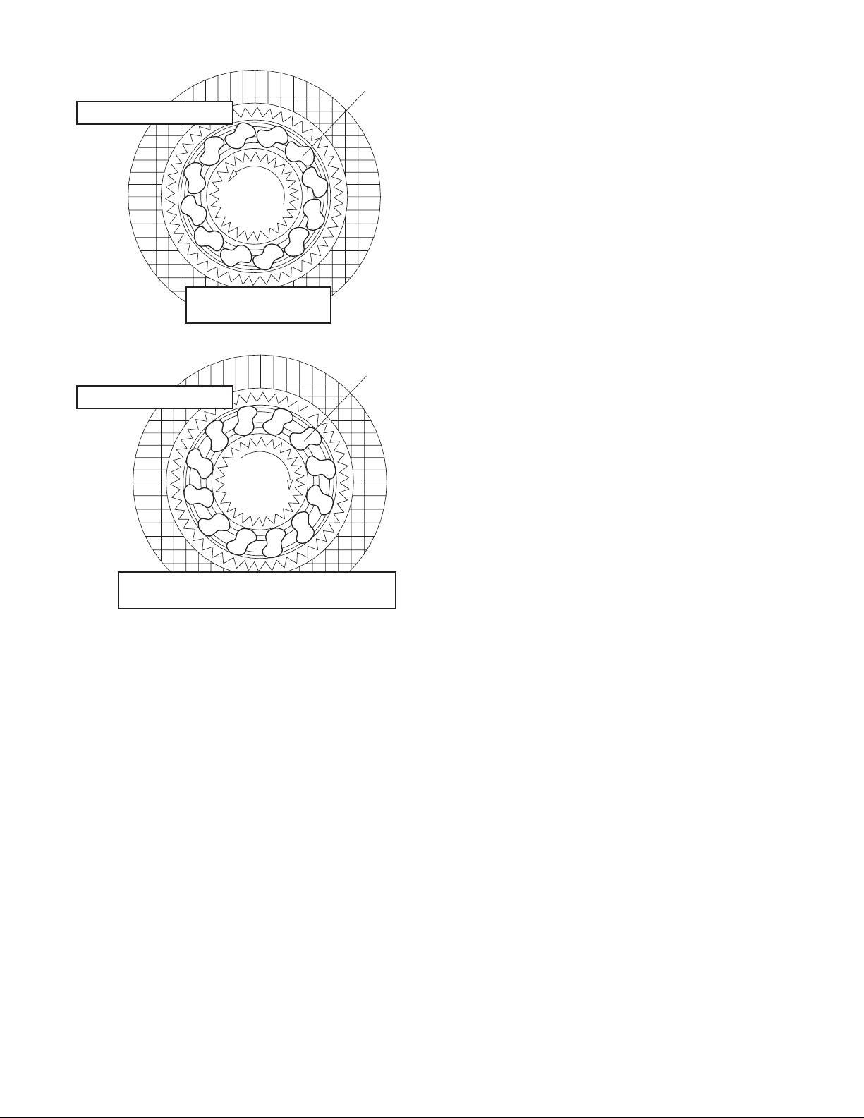
OPERATION
When hauling-in cable, or hoisting a load, the motor shaft
and winch gear train turn freely as the sprag cams lay over
between the inner and outer races of the brake clutch.
See Figure 4.
The multiple disc friction brake remains fully engaged and
the winch is not affected by any braking action. See Fig-
ure 1.
When the operation is stopped, the load tries to turn the
winch drum, gear train and primary sun gear in the re-
verse direction. This reversed input to the inner race of
the brake clutch causes the sprag cams to instantly roll
upward and lock the shaft to the fully engaged friction
brake. See Figure 5.
When the winch is powered in the pay-out or lowering di-
rection, the motor cannot rotate until sufcient pilot pres-
sure is present to release the brake and open the brake
valve. See Figures 2 and 3. The friction brake will com-
pletely release at a pressure lower than that required
to open the brake valve. The extent to which the brake
valve opens determines the amount of oil that can ow
through the motor, which is directly related to the drum
speed of the winch. Increasing the ow of oil to the winch
motor causes the pilot pressure to rise which increases
the opening in the brake valve, allowing more oil to ow
through the motor and increasing the drum speed. De-
creasing this oil ow causes the pilot pressure to drop,
reducing the opening in the brake valve which slows the
motor and winch speed.
The friction brake receives little, if any, wear in the pay-out
or lowering operation. All of the heat generated by lower-
ing and stopping a load is absorbed by the hydraulic oil
where it can be readily dissipated.
When the control valve is shifted to neutral, pilot pressure
drops closing the brake valve spool, stopping the motor
and the load. The friction brake then engages and holds
the load after the brake valve has closed.
When lowering a load slowly for precise positioning, no
oil ow actually occurs through the pilot operated spool
in the brake valve. Pressure builds up to a point where
the friction brake will release sufciently to allow the load
to rotate the motor through its own internal leakage. This
feature results in a slow speed and extremely accurate
positioning.
WINCH OPERATION
The input section of the drive assembly is bolted to the
motor end support and cannot rotate. The drive housing
is the output member of the gear set and is bolted to the
winch drum. The motor shaft is directly coupled to the pri-
mary sun gear through the inner race of the brake clutch.
The motor turns the primary sun gear which drives three
successive planetary gear sets, turning the drive housing
and the winch drum.
In the haul-in direction, hydraulic oil ows through a large
check valve in the brake valve and turns the motor in the
free rotating direction of the brake clutch, driving the gear
train and winch drum. The friction brake remains fully en-
gaged.
In the pay-out direction, oil ow through the motor is ini-
tially blocked by a spool in the brake valve. Oil pressure
supplied to the motor through the control valve is piloted
to the friction brake and the brake valve spool. The friction
brake is released at a lower pressure than that required to
shift the brake valve spool. When pressure is sufcient to
shift the brake valve spool, oil is allowed to ow through
the motor, rotating the winch gear train and drum.
Sprag Cams
Figure 4
Static Friction Brake Applied
Permits free shaft rotation
while hoisting
Sprag Cams
Figure 5
Static Friction Brake Applied
Load attempts to rotate shaft in opposite direction
Brake clutch locks sun gear shaft to friction brake

8
WINCH AND WIRE ROPE
INSTALLATION
1. The winch should be mounted with the centerline of
the cable drum in a horizontal position. The mounting
plane of the winch may be rotated in any position around
this centerline providing the vent in the motor adapter
is above the centerline of the cable drum. The vent
should be as close to top dead center as possible.
2. When mounting the winch, use all four mounting holes
and Grade 8 bolts and nuts. Evenly tighten the nuts to
the torque in the Recommended Fastener Torque chart.
Make certain the winch drum is centered behind the rst
sheave and the eet angle does not exceed 1-1/2 de-
grees. The winch should also be mounted perpendicu-
lar to an imaginary line from the center of the drum to
the rst sheave to ensure even spooling.
Refer to the dimensional drawing section of this manual
for bolt hole size and pattern.
It is important that the winch is mounted on a surface that
will not ex when the winch is in use, and cause binding of
the gear train. Binding in the gear train will result in accel-
erated wear and heat. Also, the mounting surface should
be at with +/- 0.020 inch. If necessary, install shims un-
der the winch mounting pads to achieve even mounting.
3. The hydraulic lines and components that operate the
winch should be of sufcient size to assure minimum
back pressure at the winch. The back pressure at the
motor must not exceed 100 PSI (690 kPa) to maintain
full brake system design factor and optimum motor seal
life.
The winch directional control valve must be a three-posi-
tion four-way valve with a motor spool such that when the
valve is in the center position both work ports are open to
tank (open center, open port).
4. High-quality hydraulic oil is essential for satisfactory
performance and long hydraulic system component life.
Oil having 150 to 330 SUS viscosity at 100°F (38°C) and
viscosity index of 100 or greater will give good results un-
der normal temperature conditions. The use of an oil hav-
ing a high viscosity index will minimize cold start trouble
and reduce the length of warm-up periods. A high vis-
cosity index will minimize changes in viscosity with cor-
responding changes in temperature.
Maximum cold weather start-up viscosity should not ex-
ceed 5,000 SUS with a pour point at least 20°F (11°C)
lower than the minimum ambient temperature.
Under continuous operating conditions the temperature of
the oil at any point in the system must not exceed 180°F
(82°C). 120°F (49°C) to 140°F (60°C) is generally consid-
ered optimum.
In general terms:
For continuous operation at ambient temperatures be-
tween 50°F (10°C) and 110°F (43°C) use SAE 20W; for
continuous operation between 10°F (-12°C) and 90°F
(32°C) use SAE 10W; for applications colder than 10°F
(-12°C), contact the BRADEN/GEARMATIC Service De-
partment. The use of multiviscosity oils is generally not
recommended.
For winch gear oil, refer to lubricant specications in the
Preventive Maintenance and Specications section.
5. The hydraulic oil lter should have a 10-micron nominal
rating and be full-ow type.
6. The vent plug in the motor adapter must be located as
close to top dead center as possible. If the winch is
mounted on a pivoting surface, the vent plug must re-
main above the centerline of the cable drum to prevent
gear oil leakage.
7. Refer to the dimensional drawing for relationship be-
tween drum rotation and which port is pressurized.
WIRE ROPE INSTALLATION
03 and 04 DRUM
Take the free end of the wire rope and insert it through the
small opening of the anchor pocket you are going to use.
Loop the wire rope and push the free end about three-
fourths of the way back through the pocket. Install the
cable anchor with the small end toward the drum, then pull
the slack out of the wire rope. The cable anchor will slip
into the pocket and secure the wire rope to the drum. A
minimum of ve wraps of wire rope should remain on the
cable drum at all times. Refer to General Safety Recom-
mendations section of this manual for additional informa-
tion.

9
01 and 02 DRUM – ANCHOR
Remove both sheet metal covers from the end bracket of
the winch. Pull the end of the cable through the opening in
the drum ange and out through the end bracket as shown
in Figure 1. Form the cable around part 1 of the wedge as
shown in Figure 2, and pull the assembly into the anchor
pocket (part 2 and the nut are not attached to part 1 at this
time). Access the threaded rod attached to part 1 through
the other opening in the end bracket and install part 2 and
the nut. On large diameter cable, it may be necessary to
hammer on the cable looped around part 1 to force it far
enough into the anchor pocket to attach part 2.
It is important for the dead end of the cable to extend be-
yond the end of part 2, as shown in Figure 2, but not far
enough to come in contact with the end bracket when winch
is operating. A load should be applied to the live end of the
cable to properly seat the anchor. After initial load is ap-
plied, tighten nut holding part 2 in place to 11 ft-lbs. A mini-
mum of ve wraps of wire rope should remain on the cable
drum at all times. Refer to General Safety Recommenda-
tions section of this manual for additional information.
3-piece Cable Anchor Installation
(specic to model CH400)
Install threaded rod (Item 3) into Item 1 until it bottoms,
then tighten jam nut (Item 2) against Item 1.
Feed cable through opening in drum ange until it extends
outside cable pocket 2 to 4 inches.
Insert partially assembled anchor (Items 1, 2, 3) into the
cable pocket with at side of Item 1 against the drum
ange. The anchor will wedge between the cable and the
top of the cable pocket.
Working from the other end of the cable pocket, install
Item 4 onto the threaded rod. Be sure to place the at side
of Item 4 against the drum ange, then install the rounded
end onto the threaded rod rst so the washer (Item 5) and
locknut (Item 6) will seat against the at end.
Install the washer and locknut onto the threaded rod and
tighten securely to 45 ft-lbs. (This is the torque value of the
1/2-13 stainless-steel rod).
Apply a light load of 1,000 to 2,000 pounds on the cable
and carefully spool it onto the drum. Retighten the nut
again to 45 ft-lbs.
These surfaces face toward
drum ange when installed.
Figure 3
The cable anchor is not designed to hold the rated load
of the hoist. DO NOT apply full rated load until ve or
more wraps of cable are on the drum. A sudden loss
of load control could cause property damage, personal
injury, or death.
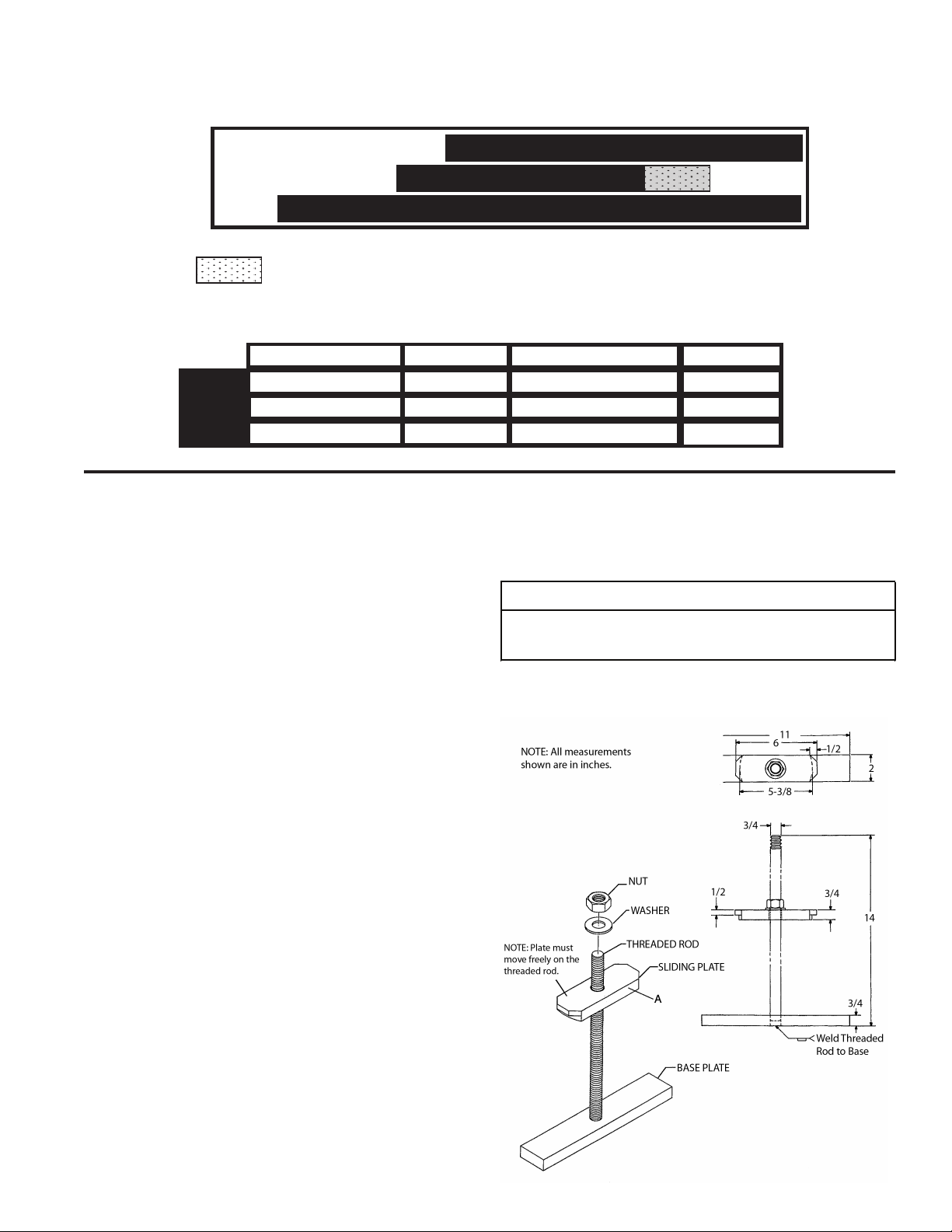
SPECIAL OFFSHORE BREAKAWAY ANCHOR
NOTE: Conrm that the cable
clamp assembly is suitable
for your rope size by read-
ing the size range (in inches)
stamped on part itself.
Example
01 AND 02 DRUM – ANCHOR
Remove both sheet metal covers from the end bracket
of the winch. Pull the end of the cable through the
opening in the drum flange and out through the end
bracket as shown in figure 1. Form the cable around
part 1 of the wedge as shown in figure 2, and pull the
assembly into the anchor pocket (part 2 and the nut are
not attached to part 1 at this time). Access the threaded
rod attached to part 1 through the other opening in the
end bracket and install part 2 and the nut. On large
diameter cable, it may be necessary to hammer on the
cable looped around part 1 in order to force it far
enough into the anchor pocket to attach part 2. It is
important for the ‘dead’ end of the cable to extend
beyond the end of part 2, as shown in figure 2, but not
far enough to come in contact with the end bracket
when the winch is operating. A load should be applied
to the ‘live’ end of the cable to properly seat the anchor.
After the initial load is applied, check the tightness of
the nut holding part 2 in place and tighten it if required.
A minimum of five (5) wraps of wire rope should remain
on the cable drum at all times. Refer to “General Safety
Recommendations” for additional information.
–– 7 ––
Figure 1
Figure 2
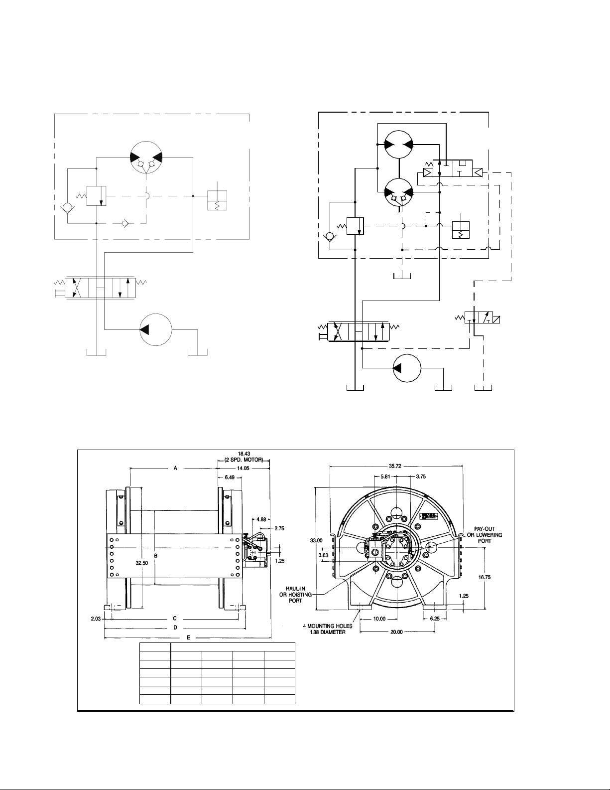
HYDRAULIC CIRCUITS
SINGLE SPEED CIRCUIT 2 SPEED CIRCUIT
Part
2
Part
1
10
DIMENSIONAL
HYDRAULIC CIRCUITS
SINGLE-SPEED CIRCUIT 2-SPEED CIRCUIT
HOIST BRAKE
BRAKE
VALVE
PUMP
CONTROL
VALVE
HOIST ASSEMBLY
W/BRAKE VALVE
& STATIC BRAKE
BR
DR
WINCH BRAKE
BRAKE
VALVE
2-SPEED
SELECTOR
VALVE
PUMP
CONTROL
VALVE
WINCH ASSEMBLY
W/BRAKE VALVE
& STATIC BRAKE
T P
BR
DR
A
PREVENTIVE
MAINTENANCE
A regular program of preventive maintenance for your
planetary winch is strongly recommended to minimize
the need for emergency servicing and promote safe,
reliable winch operation
Field experience supported by engineering tests, indi-
cates the three (3) service procedures listed below are
the MOST critical to safe, reliable winch operation and
must be observed.
•Regular Gear Oil Changes – every 1000 hours or
six (6) months.
•Use of Proper Gear Oil – recommended type for
prevailing ambient temperature.
• Annual Disassembly and Inspection of All Wear
Items – in compliance with American National
Standards Institute (ANSI) specification B30.5c 1987
and American Petroleum Institute (API) recom-
mended practice RP 2D section 3.
The following minimum service intervals are specified
for operating hours of the prime mover.
1. Oil Level
3. The gear oil level should be checked every 500
operating hours or three (3) months, whichever
occurs first. Oil level should be even with the cen-
terline of the winch drum. Rotate the winch drum
until the level plug can be seen in one of the two
access holes on either side of the drum support and
remove the plug.The oil should be level with the bot-
tom of this opening. If additional oil is needed, refer
to “Recommended Planetary Gear Oil”.
2. Oil Change
3. The gear oil should be changed after the first one
hundred (100) hours of operation, then every 1,000
operating hours or six (6) months, whichever occurs
first. The gear oil must be changed to remove wear
particles that impede the reliable and safe opera-
tion of the brake clutch and erode bearings, gears
and seals. Failure to change gear oil at these sug-
gested minimum intervals may contribute to inter-
mittent brake slippage which could result in property
damage, severe personal injury or death.
3. Rotate the drum until the -8 drain plug is aligned with
the lowest opening in the drum end support plate.
Install a short piece of 1 inch pipe through the end
plate. Reach through the pipe with a 5⁄16 hex allen
wrench and remove the -8 plug to drain the oil. Install
the -8 plug and remove the 1 inch pipe when all the
oil has been drained from the drum. Although gear
oil circulates between the drive and the drum
through holes in the primary ring gear, it is advis-
able to also remove the plug in the rotating part of
the winch drive to drain any trapped oil in the drive.
This is done by aligning the plug with the opening
in the support bracket directly below the winch
motor.
3. The gear oil should also be changed whenever the
ambient temperature changes significantly and an
oil from a different temperature range would be more
appropriate.Oil viscosity with regard to ambient tem-
perature is critical to reliable brake operation. Make
certain that the gear oil viscosity used in your winch
is correct for your prevailing ambient temperature.
Failure to use the proper type and viscosity of plan-
– 8 –
DIMENSIONAL
DRUM
01 02 03 04
A23.88 38.13 23.88 38.13
B20.00 20.00 22.0-0 22.00
C34.29 48.54 34.29 48.54
D38.35 52.60 38.35 52.60
E45.16 59.41 45.16 59.41
NOTE: Add 4.38 inches to Dimension “E” for 2
Speed Motor.(All Dimensions in Table and
Drawing are inches). See Publication PB-188 for
performance data.

11
PREVENTIVE MAINTENANCE
A regular program of preventive maintenance for your
planetary winch is strongly recommended to minimize the
need for emergency servicing and promote safe, reliable
winch operation.
Field experience, supported by engineering tests, indi-
cates the three service procedures listed below are the
MOST critical to safe, reliable winch operation and must
be observed.
• Regular Gear Oil Changes – every 1,000 hours or
six months
• Use of Proper Gear Oil – recommended type for pre-
vailing ambient temperature
• Annual Disassembly and Inspection of All Wear
Items – in compliance with American National Stan-
dards Institute (ANSI) specication B30.5c 1987 and
American Petroleum Institute (API) recommended
practice RP 2D section 3.
The following minimum service intervals are specied for
operating hours of the prime mover.
1. Oil Level
The gear oil level should be checked every 500 operat-
ing hours or three months, whichever occurs rst. Oil
level should be even with the centerline of the winch
drum. Rotate the winch drum until the level plug can
be seen in one of the two access holes on either side of
the drum support and remove the plug. The oil should
be level with the bottom of this opening. If additional oil
in needed, refer to Recommended Planetary Gear Oil
section of this manual.
2. Oil Change
The gear oil should be changed after the rst one hun-
dred (100) hours of operation, then every 1,000 oper-
ating hours or six months, whichever occurs rst. The
gear oil must be changed to remove wear particles that
impede the reliable and safe operation of the brake
clutch and erode bearings, gears and seals. Failure to
change gear oil at these suggested minimum intervals
may contribute to intermittent brake slippage which
could result in property damage, severe personal in-
jury, or death.
Rotate the drum until the –8 drain plug is aligned with
the lowest opening in the drum end support plate. In-
stall a short piece of 1-inch pipe through the end plate.
Reach through the pipe with a 5/16 hex Allen wrench
and remove the –8 plug to drain the oil. Install the
–8 plug and remove the 1-inch pipe when all the oil
has been drained from the drum. Gear oil circulates
between the drive and the drum through holes in the
primary ring gear, you must also remove the plug in the
rotating part of the winch drive to drain any trapped oil
in the drive. This is done by aligning the plug with the
opening in the support bracket directly below the winch
motor.
The gear oil should also be changed whenever the am-
bient temperature changes signicantly and an oil from
a different temperature range would be more appropri-
ate. Oil viscosity with regard to ambient temperature is
critical to reliable brake clutch operation. Make certain
that the gear oil viscosity used in your winch is cor-
rect for your prevailing ambient temperature. Failure
to use the proper type and viscosity of planetary gear
oil may contribute to brake slippage which could result
in property damage, severe personal injury, or death.
Refer to Recommended Planetary Gear Oil section of
this manual for additional information.

12
3. Vent Plug
The vent plug is located directly above the winch mo-
tor near the brake release port. It is important to keep
this vent clean and unobstructed. Whenever gear oil is
changed, remove vent plug, clean in solvent and rein-
stall.
Do not paint over the vent or replace with a solid plug.
4. Hydraulic System
The original lter element should be replaced after
the rst 50 hours of operation, then every 500 operat-
ing hours or three months, or in accordance with the
equipment manufacturer’s recommendations.
5. Wire Rope
Inspect entire length of wire rope according to wire
rope manufacturer’s recommendations.
6. Mounting Bolts
Tighten all winch base mounting bolts to recommended
torque after the rst one hundred (100) hours of opera-
tion, then every 1,000 operating hours or six months,
whichever occurs rst.
7. Warm-up Procedures
A warm-up procedure is recommended at each start-
up and is essential at ambient temperatures below
+40°F (4°C).
The prime mover should be run at its lowest recom-
mended RPM with the hydraulic winch control valve in
neutral allowing sufcient time to warm up the system.
The winch should then be operated at low speeds,
forward and reverse, several times to prime all lines
with warm hydraulic oil, and to circulate gear lubricant
through the planetary gear sets.
8. Recommended Planetary Gear Oil
Field experience, supported by extensive engineering
tests, indicates the use of the proper planetary gear oil
is essential to reliable and safe operation of the brake
and obtaining long gear train life.
For simplicity, we have listed one readily available
product in each temperature range which has been
tested and found to meet our specications. This is not
to say that other lubricant brands would not perform
equally as well.
If the following lubricant brands are not available in
your area, make certain your lubricant vendor supplies
you with oil that is equivalent to those products listed
on following page.
CH330/CH400 planetary winches are factory lled with
Texaco Meropa 150 or equivalent.
9. Inspection
In compliance with ANSI specication number
B30.5c1987 and API Recommended Practice RP 2D
section 3, we recommend that the winch be disassem-
bled for a thorough inspection of all wear items every
2,000 hours of operation or 12 months, whichever oc-
curs rst.
Failure to properly warm up the winch, particularly un-
der low ambient temperature conditions, may result in
temporary brake slippage due to high back pressures
attempting to release the brake, which could result in
property damage, severe personal injury, or death.
Failure to use the proper type and viscosity of planetary
gear oil may contribute to intermittent brake clutch slip-
page which could result in property damage, severe
personal injury, or death. Some gear lubricants contain
large amounts of extreme pressure (EP) and antifric-
tion additives which may contribute to brake slippage
and damage to brake friction discs or seals. Oil viscos-
ity with regard to ambient temperature is also critical to
reliable brake operation. Our tests indicate that exces-
sively heavy or thick gear oil may contribute to intermit-
tent brake slippage. Make certain that the gear oil vis-
cosity used in your winch is correct for your prevailing
ambient temperature.
13
WEIGHTS, OIL CAPACITIES,
AND SPECIAL TOOLS
SPECIAL TOOLS
2 each 5/16-18NC eyebolt
2 each 1/2-13NC eyebolt
2 each 3/4-10NC eyebolt:
NOTE: The rst two items below are required only if the
motor support is separated from the ring gear.
The other tools are required to service the brake
assembly.
a) 1-inch diameter bar approximately 36 inches
long and various sized small steel blocks (key
stock).
b) 3 each 7/8-9NC x 6-inch long capscrews
c) A ratcheting internal snap ring pliers capable of
handling an N5000 700 snap ring.
All units use a single coil spring to apply the inter-
nal brake. The following spring compressor must
be fabricated and is strongly recommended.
NOTE: If a press is available (with at least 5 inches of trav-
el), only part A (shown at right) is required (center
hole not required). If a press is not available, all
parts shown and listed below are required.
a) 1 each 3/4-16NF threaded rod, 4 inches long
b) 1 each 3/4-16NF nuts
c) 1 each 3/4-inch plain washer
Ferry capscrew sockets 3/4-inch drive 12 point
5/8-inch Proto P/N – J07510T
Snap-On P/N – IMD202A
3/4-inch Proto P/N J07512T
Snap-On P/N IMD242A
APPROXIMATEAPPROXIMATE
DRUMWEIGHT (LBS/KG) OIL CAPACITY (QTS/L)
01 2700/1225 40/38
02 3370/153
06
5/61.5
21 3800/1725 90/85
PREVAILING AMBIENT TEMPERATURE
oF -40 -30 -20 -10 0 10 20 30 40 50 60 70 80 90 100 110 120 130 oF
oC -40 -30 -20 -10 0 10 20 30 40 50 oC
SHADED TEMPERATURE RANGE IN THE CHART ABOVE NOT RECOMMENDED FOR SEVERE APPLICATIONS SUCH AS SUSTAINED
FAST DUTY CYCLES OR FREQUENT WINCHING.
TexacoShell
Meropa 220
Meropa 150
Omala S2 G 220
Omala S2 G 150
Chevron
Gear Compounds EP 220
Gear Compounds EP 150
PREVAILING AMBIENT TEMPERATURE
oF -40 -30 -20 -10 0 10 20 30 40 50 60 70 80 90 100 110 120 130 oF
oC -40 -30 -20 -10 0 10 20 30 40 50 oC
SHADED TEMPERATURE RANGE IN THE CHART ABOVE NOT RECOMMENDED FOR SEVERE APPLICATIONS SUCH AS
Mobil
Mobilgear 600 XP 220
Mobilgear 600 XP 150
Winches are factory filled with Mobilgear 600 XP 150 or equivalent. Consult your oil supplier for other equivalent
oils if required.
RECOMMENDED GEAR OIL
Omala S4 GX 150
Mobilgear SHC 150
Use gear oil detailed in Range A
Range A
Range B
Range C
Use gear oil detailed in Range B
Use gear oil detailed in Range C

14
TROUBLESHOOTING
A
The winch will not lower
the load or not lower the
load smoothly.
1. The friction brake may not be releasing
as a result of a defective brake cylinder
seal.
NOTE: If the brake cylinder seal is defec-
tive you will usually nd oil leaking from
the winch vent plug.
2. Friction brake will not release as a re-
sult of damaged brake discs.
Check brake cylinder seal as follows:
A. Disconnect the swivel tee from the brake
release port. Connect a hand pump with ac-
curate 0-2000 PSI (0-13,000 kPa) gauge
and shut-off valve to the –4 JIC tting in the
brake release port.
B. Apply 1,000 PSI (6,900 kPa) to the brake.
Close shut-off valve and let stand for ve
minutes.
C. If there is any loss of pressure in ve
minutes, the brake cylinder should be dis-
assembled for inspection of the sealing sur-
faces and replacement of the seals. Refer
to “Motor Support-Brake Cylinder Service.”
Disassemble brake to inspect brake discs.
B
Oil leaks from vent plug. 1. Same as A1.
2. Motor seal may be defective as a result
of high system back pressure or con-
taminated oil.
Same as A1.
System back pressure must not exceed 150
PSI (1,030 kPa) for gear motor. 30 PSI for
piston motor. Inspect hydraulic system for a
restriction in the return line from the control
valve to the reservoir. Be sure control valve
and plumbing is properly sized to winch mo-
tor.
Oil analysis may indicate contamination has
worn motor shaft and seal. Thoroughly ush
entire hydraulic system and install new l-
ters and oil. Install new motor seal.
TROUBLE PROBABLE CAUSE REMEDY
If a winch exhibits any sign of erratic operation or load-
control difculties (such as load creeping or chattering),
appropriate troubleshooting tests and repairs should
be performed immediately. Continued operation in this
manner may result in property damage, serious person-
al injury, or death.

15
C
The brake will not hold a
load with the control lever
in neutral.
1. Excessive system back pressure acting
on the brake release port.
2. Friction brake will not hold due to worn
or damaged brake discs.
3. Brake clutch is slipping.
Same as remedy for Trouble B2.
Same as remedy for Trouble A2.
Improper planetary gear oil may cause the
brake clutch to slip. Drain old gear oil and
ush winch with solvent. Thoroughly drain
solvent and rell winch with recommended
planetary gear oil listed in “Preventive Main-
tenance.”
Brake clutch may be damaged or worn. Dis-
assemble and inspect brake clutch as de-
scribed in “Brake Clutch Service.”
D
The winch will not hoist the
rated load.
1. The winch may be mounted on an un-
even or exible surface which causes
distortion of the winch base and bind-
ing of the gear train. Binding in the gear
train will absorb horsepower needed to
hoist the rated load and cause heat.
2. System relief valve may be set too low.
Relief valve needs adjustment or re-
pair.
3. Be certain hydraulic system tempera-
ture is not more than 180°F (82°C).
Excessive hydraulic oil temperatures
increase motor internal leakage and re-
duce motor performance.
4. Winch line pull rating is based on 1st
layer of wire rope.
5. Rigging and sheaves not operating ef-
ciently.
Reinforce mounting surface.
If necessary, use shim stock to level winch.
Refer to “Winch Installation.”
First loosen, then evenly retighten all winch
mounting bolts to recommended torque.
Check relief pressure as follows:
A. Install an accurate 0-4000 PSI (28,000
kPa) gauge into the inlet port of the brake
valve.
B. Apply a stall pull load on the winch while
monitoring pressure.
C. Compare gauge reading to winch speci-
cations. Adjust relief valve as required.
NOTE: If pressure does not increase in pro-
portion to adjustment, relief valve may be
contaminated or worn out. In either case,
the relief valve may require disassembly or
replacement.
Same as remedies for Trouble D1 and D2.
Same as remedies for Trouble E2.
Refer to winch performance charts for ad-
ditional information.
Perform rigging service as recommended by
crane manufacturer.
TROUBLE PROBABLE CAUSE REMEDY

16
E
The winch runs hot. 1. Same as D1.
2. Be certain that the hydraulic system
temperature is not more than 180°F
(82°C). Excessive hydraulic oil tem-
peratures may be caused by:
A. Plugged heat exchanger.
B. Too low or too high oil level in hydraulic
reservoir.
C. Same as D2.
D. Hydraulic pump not operating efcient-
ly.
3. Excessively worn or damaged internal
winch parts.
Same as remedies for Trouble D1.
Thoroughly clean exterior and ush interior.
Fill/drain to proper level.
Same as remedies for Trouble D2.
Prime mover low on horsepower or RPM
Tune/adjust prime mover.
Check suction line for damage.
If pump is belt driven, belts are slipping. Re-
place/tighten belts.
Pump worn. Replace pump.
Disassemble winch to inspect/replace worn
parts.
F
Winch chatters while rais-
ing rated load.
1. Same as D2.
2. Hydraulic oil ow to motor may be too
low.
3. Controls being operated too quickly.
Same as remedies for Trouble D2.
Same as remedies for Trouble E2.
Conduct operator training as required.
G
The wire rope does not
spool smoothly on the
drum.
1. The winch may be mounted too close
to the main sheave, causing the eet
angle to be more than 1-1/2 degrees.
2. The winch may not be mounted perpen-
dicular to an imaginary line between
the center of the cable drum and the
rst sheave.
3. Could possibly be using the wrong lay
rope. There is a distinct advantage in
applying rope of the proper direction
of lay. When the load is slacked off,
the several coils on the drum will stay
closer together and maintain an even
layer. If rope of improper lay is used,
the coils will spread apart each time the
load is removed. Then, when winding
is resumed, the rope has a tendency
to criss-cross and overlap on the drum.
The result is apt to be a attened and
crushed rope.
4. The winch may have been overload-
ed, causing permanent set in the wire
rope.
Check mounting distance and eet angle.
Reposition winch as required.
Refer to “Winch Installation.”
Consult wire rope manufacturer for recom-
mendation of wire rope that best suits your
application.
Replace wire rope and conduct operator/
rigger training as required.
TROUBLE PROBABLE CAUSE REMEDY
17
Before any part is removed from the winch or drive gear-
box, all service instructions should be read and under-
stood.
Work in a clean, dust free area as cleanliness is of utmost
importance when servicing hydraulic equipment.
Inspect all replacements parts, prior to installation, to de-
tect any damage which might have occurred in shipment.
Use only genuine BRADEN replacement parts for opti-
mum results. Never reuse expendable parts such as O-
rings and oil seals.
Inspect all machined surfaces for excessive wear or dam-
age before reassembly operations are begun.
Lubricate all O-rings and oil seals with gear oil prior to
installation.
Lubricate all bearings with an oil soluble grease prior to
assembly.
Use a sealing compound on the outside surface of oil
seals and a light coat of thread sealing compound on pipe
threads. Avoid getting sealing compound inside parts or
passages which conduct oil.
Before beginning to disassemble the winch or drive gear-
box, remove the wire rope, drain the oil and clean the out-
side surfaces to avoid contaminating gears and bearings.
Item numbers shown in service procedures are referenced
to the exploded-view drawing in this manual.
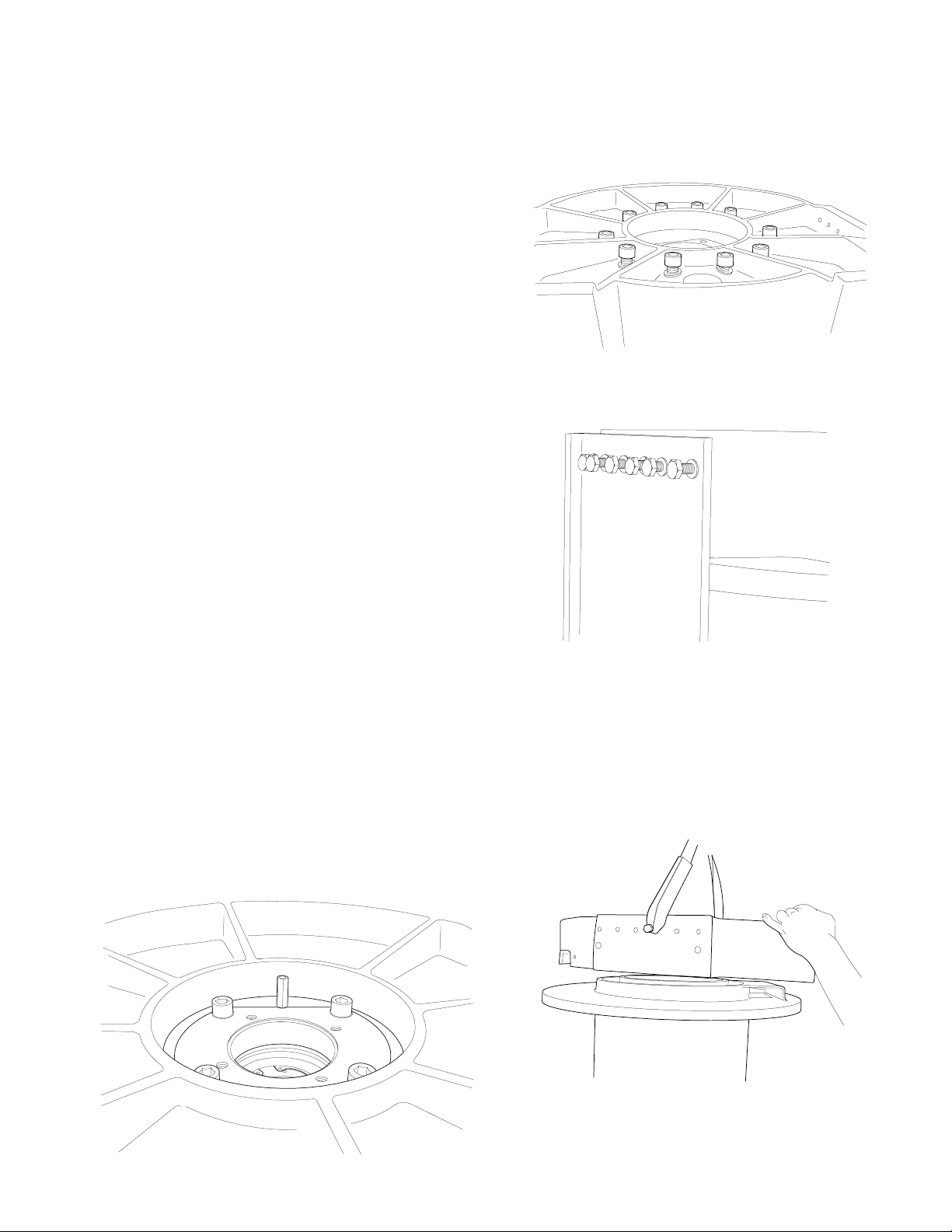
WINCH DISASSEMBLY
1. Stand the winch of the end opposite the motor. Re-
move the hydraulic hose that connects the brake valve
and motor to the brake release port. Remove the four
capscrews securing the motor to the winch and lift off
the motor/brake valve assembly. Remove and discard
the O-ring installed on the outside of the motor pilot.
2. Remove the four capscrews from the motor adapter
and remove the motor adapter (Item 27) from the drive
gearbox. Remove and discard the O-ring (Item 26)
from the motor adapter.
3. Remove the 10 capscrews and lockwashers securing
the end bracket (Item 25) to the gearbox.
4. Remove the 24 capscrews and lockwashers securing
the tie plates (Item 1) to both end brackets and remove
the tie plates. The tie plates have two dowel pins in each
end and may have to be lightly tapped or pried from the
end brackets. Install four large C-clamps around the
drum support end bracket (Item 2) and the drum ange.
This will prevent the end bracket and drum from sepa-
rating when the motor end bracket and winch drive are
removed.
5. Lift the motor end bracket (Item 25) from the drum/drive
assembly.
SERVICE PRECAUTIONS
18
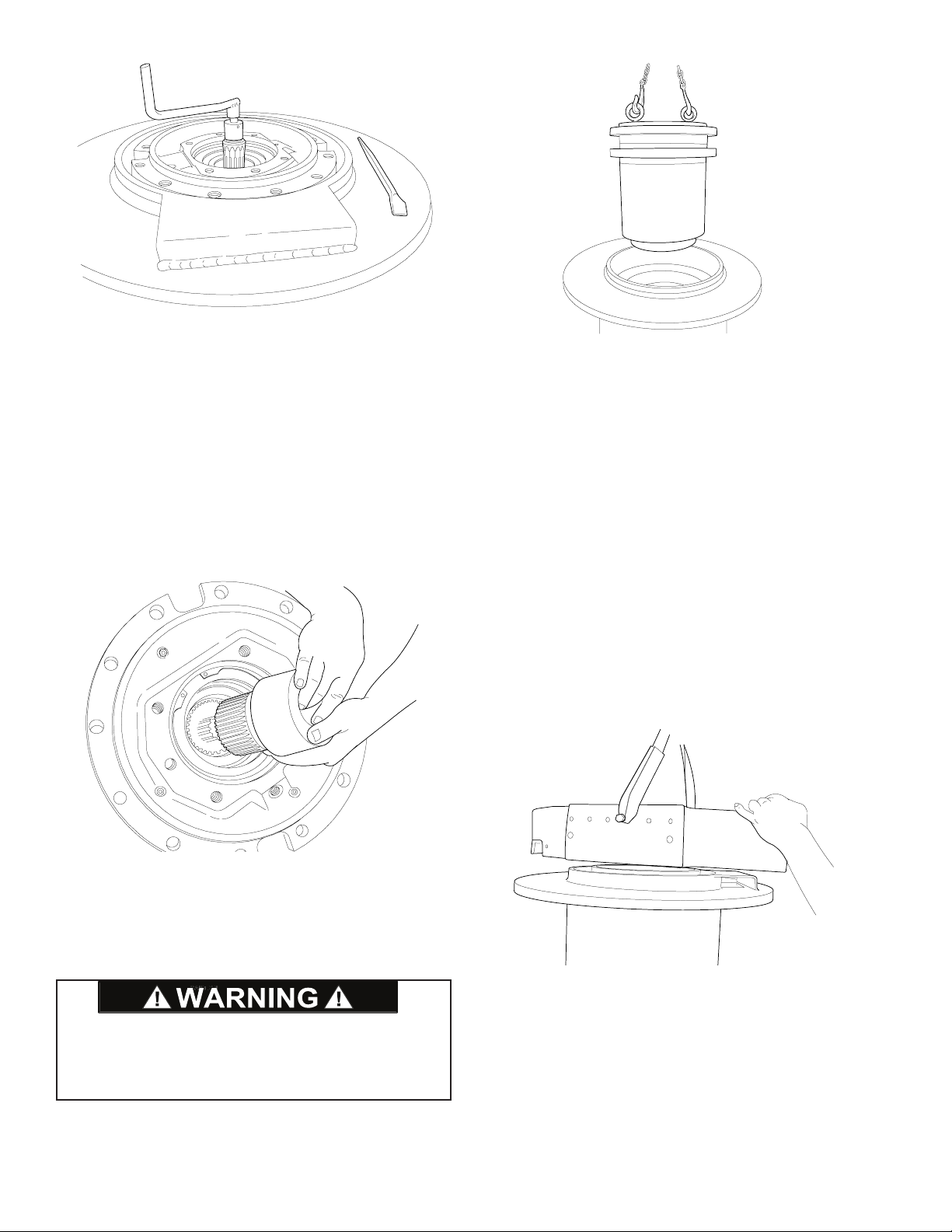
6. There are two large notches in the end of the drive
gearbox. These must be rotated to gain access to the
capscrews and lockwashers (Items 4 and 5) that secure
the gearbox to the winch drum. This is done by rotating
the motor coupling while keeping the drum from turning.
Continue this procedure and remove all capscrews and
lockwashers (Items 4 and 5).
NOTE: To obtain relative movement between the two
sections of the gearbox, the input shaft must be rotated
in the same direction as the motor turns to haul-in ca-
ble. Rotating the shaft in the opposite direction results
in the entire gearbox and drum turning as a single unit.
7. The brake clutch assembly and motor coupling should
now be removed from the gearbox.
NOTE: The sun gear will remain in the gearbox and
cannot be removed from this end.
8. Lift the winch drive gearbox out of the drum using two
7/8 NC eyebolts spaced 180 degrees apart as lifting
lugs. Refer to Winch Drive/Gearbox Service section for
further disassembly of winch drive.
DRUM SUPPORT
END BRACKET SERVICE
If the winch disassembly procedure has been followed to
this point, remove the C-clamps installed in step 4. If only
this end of the winch is being serviced, support the winch
on the motor end bracket and remove the 12 capscrews
and lockwashers securing the end of both tie plates (Item
1), to the drum support end bracket (Item 2). Loosen
the 12 capscrews on the other end of both tie plates just
enough to allow the tie plates to be pried free of the dowel
pins in the drum support end bracket.
1. Lift the support end bracket from the drum.
NOTE: If the winch disassembly procedure was fol-
lowed and the drum is on top of the end bracket, lift the
drum from the support end bracket.
DO NOT attempt to remove the large retaining ring at
this time. It is holding the static brake spring in com-
pression. Removing this retaining ring at this time could
result in property damage, personal injury, or death.

19
105
106
15
20
21
19
4
5
11
10
3
22
3
23
2
7
13
12
14
8
9
6
18
17
15
16
31
1
24
68
69
70
71
69
64
73
74
75
76
79
77
61
63
62
61
56
67
65
66
72
58
57
64
60
59
56
55
40
41
42
44
43
81
82
4
5
45
80
51
52
53
47
46
50
49
48
78
75
74
83
84
85
32
54
95
86
87
88
89
90 95
96
97
98
99
100
101
28
91
92
93
94
102
103
104
26
27
4
33
30
29
25
20
Two-speed
Motor
Single-speed
Motor
ITEM ITEM ITEM ITEM
NUMBE
R DESCRIPTION NUMBER DESCRIPTION NUMBER DESCRIPTIONNUMBER DESCRIPTION
1Tie Plate31Dowel Pin67Second Stage Planet Carrier 97 Roller Bearing
2Support End Plate32Pipe Plug 68 Planet Pin98Spacer
3O-Ring Flush Plug 33 Capscrew 69 Thrust Washer 99 Sprag Clutch Assembly
4Lockwasher40Thrust Washer 70 Second Stage Planet Gear 100Spacer
5Capscrew 41 Thrust Washer 71 Loose Rollers101 Internal Retaining Ring
6Outer Bearing Hub42 Primary Ring Gear/End Cover72Output Planet Carrier102 Sprag Clutch Inner Race
7I
nternal Retaining Ring
43 Capscrew 73 Planet Pin103 Spacer
8Roller Bearing44Lockwasher74Bearing Cone 104Internal Retaining Ring
9Grease Fitting45Ring Gear 75 Bearing Cup105 Cable Wedge (01 & 02 Drum)
10
Inner Bearing Hu
b46Drain Tube 76 Output Planet Gear 106Cable Wedge (03 & 04 Drum)
11 Ex
ternal Retaining Ring
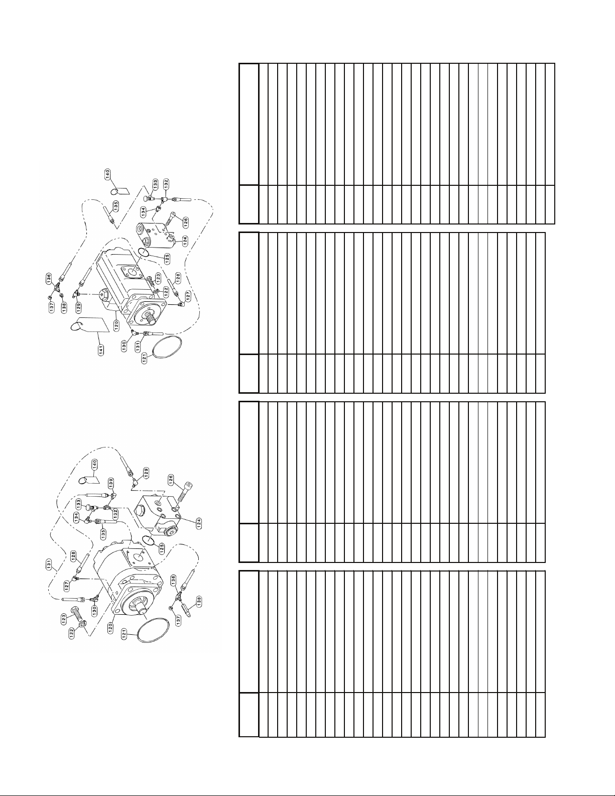
47 Plug 77 Bearing Spacer 120Hydraulic Motor
12 Seal 48 Split Ring 78 Internal Retaining Ring 121O-Ring
13 Seal Carrier 49 Bearing Cone 79 Rollpin 122Lockwasher
14 O-Ring 50 Bearing Cup80Plug123 Capscrew
15 Lockwasher51Bearing Cup81Internal Retaining Ring 124Brake Valve
16 Capscrew 52 Bearing Cone 82 Brake Spacer/Support Plate125 O-Ring
17 Capscrew 53 Metal Face Seal 83 Steel Brake Disk 126Capscrew
18 Lockwasher54Vent Plug 84 Friction Brake Disk 127Reducer Elbow
19 Sight Gauge 55 Primary Sun Gear 85 Motor Support/Brake Cylinder 128Hydraulic Hose
20 Capscrew 56 External Retaining Ring 86 Back-Up Ring 129Elbow Fitting
21 Cover Plate57Thrust Washer 87 O-Ring 130Elbow Fitting
22 O-Ring 58 Second Stage Sun Gear 88 O-Ring 131Hydraulic Hose
23 Cable Drum 59 Primary Planet Carrier89Back-Up Ring 132Tee Fitting
24 O-Ring 60 Planet Pin90Brake Piston 133Needle Valve
25 Motor End Plate61Thrust Washer 91 Brake Spring 134Elbow Fitting
26 O-Ring 62 Primary Planet Gear 92 Brake Piston Stop 135Hydraulic Hose
27 Motor Adapter63Loose Rollers93Spring Stop 136Male Branch Tee Fitting
28 Motor Coupling64Rollpin 94 Internal Retaining Ring 137Cap Nut
29 Capscrew 65 Thrust Washer 95 Bushing138 Nipple
30 Lockwasher66Output Sun Gear 96 Sprag Clutch Outer Race 139Elbow Fitting
140Warning Tag
This manual suits for next models
1
Table of contents
Other BRADEN Winch manuals


Popular Winch manuals by other brands

OZ Lifting Products
OZ Lifting Products OZ1500BW Operator's manual

REMA
REMA WW Series owner's manual

Warn
Warn 93790 installation instructions

MOMENT
MOMENT 6438014351513 Assembly & operating instructions

Shark
Shark 800-102601 Operation manual

Harken
Harken Performa Winch 80.2 STP Installation and maintenance manual


