BRADEN HP35A Manual

1
LIT2476 R1
4/2010
PRINTED IN U.S.A.
PACR WINCH DIVISION
P.O. BOX 547 BROKEN ARROW, OK U.S.A.7401
3
PHONE (918) 251-8511 FAX (918) 259-1575
www.paccarwinch.com
INSTALLATION, MAINTENANCE, AND SERVICE MANUAL
HP35A
HYDRAULIC PLANETARY
RECOVERY WINCH

2
Table Of Contents
FOREWORD..........................................................................................................3
GENERAL SAFETY RECOMMENDATIONS .........................................................4
DESCRIPTION OF OPERATION (with Overrunning Clutch).................................6
DESCRIPTION OF OPERATION (Winch Extension Shaft) ...................................8
WINCH INSTALLATION.........................................................................................9
TYPICAL HYDRAULIC CIRCUIT.........................................................................10
WIRE ROPE INSTALLATION...............................................................................12
PRE-DELIVERY CHECKLIST..............................................................................12
WINCH OPERATION ...........................................................................................13
DRUM CLUTCH OPERATION.............................................................................14
CAPSTAN USE ....................................................................................................16
AUXILIARY RIGGING..........................................................................................17
PREVENTIVE MAINTENANCE............................................................................18
SPECIFICATIONS................................................................................................20
TROUBLESHOOTING .........................................................................................21
SERVICE PRECAUTIONS...................................................................................25
RECOMMENDED BOLT TORQUE......................................................................25
HP35A COMPONENT EXPLOSION....................................................................26
HP35 COMPONENT PARTS KEY.......................................................................27
WINCH DISASSEMBLY.......................................................................................28
WINCH ASSEMBLY .............................................................................................29
PLANET CARRIER SERVICE..............................................................................31
BRAKE CYLINDER SERVICE .............................................................................34
BRAKE CLUTCH SERVICE.................................................................................37
BRAKE VALVE SERVICE.....................................................................................39
LOW SPEED HIGH TORQUE HYDRAULIC MOTOR..........................................41
TWO-SPEED HYDRAULIC MOTOR....................................................................42
LOW SPEED HIGH TORQUE CHANGING DIRECTION OF ROTATION............43
HP35A ROTATION CHANGE...............................................................................44
RECOMMENDED PLANETARY GEAR OIL.........................................................45
EXPLANATION OF MODEL NUMBER
HP 35 A - 35 119 - 01 - EB
HP DESIGNATES HYDRAULIC PLANETARY RECOVERY WINCH
35 DESIGNATES 35,000 POUND FIRST LAYER LINE PULL
A DESIGNATES THE MODEL SERIES RELATING TO DESIGN CHANGES
35 DESIGNATES TOTAL GEAR REDUCTION
119 DESIGNATES HYDRAULIC MOTOR DISPLACEMENT (119 - 11.9 CU IN/REV)
01 DESIGNATES THE DRUM OPTION
EB DESIGNATES THE EXTENSION SHAFT

3
FOREWORD
Read and understand this manual before operating or servicing your BRADEN winch. Retain this manual for future
reference.
The minimum service intervals specified are for the operating hours of the prime mover.
This manual contains installation, operation and preventive maintenance instructions for current Model HP35 BRADEN
Planetary Recovery winches.As there are many product variations, you must become familiar with your BRADEN winch
to fully benefit from the information contained within this publication.
Some illustrations in this manual may show details or attachments that may be different from your winch, and some
components may be removed for illustrative purposes.
Whenever a question arises regarding your BRADEN winch or this manual, please contact your nearest BRADEN dis-
tributor or the PACCAR Winch Division Product Support Department at (918)-251-8511, Monday – Friday, 0800 – 1630
hours CST, by fax at (918)-259-1575, or via the internet at www.paccarwinch.com. Provide the complete winch model
and serial number when making inquiries.
Parts and Service
BRADEN provides parts and service through a network of BRADEN distributors. Parts and service are not available
directly from the PACCAR Winch Division. For the name of your nearest BRADEN distributor, consult your local phone
directory, or contact BRADEN as defined above.
MODEL NUMBER
SERIAL NUMBER
The winch model number is an important refer-
ence as to what optional components were used
when the winch was manufactured. The model
and serial numbers are stamped into the gear
housing as shown above. Record the information below for future reference.
Always include the model and serial numbers when
inquiring or ordering parts.
Model No. ________________________________
Serial No. ________________________________
In-Service Date ___________________________

4
GENERAL SAFETY RECOMMENDATIONS
Safety informational callouts used in this manual include:
This emblem is used to warn against hazards and un-
safe practices which COULD result in severe injury or
death if proper procedures are not followed.
Safety for operators and ground personnel is of prime con-
cern.Always take the necessary precautions to ensure the
safety of others as well as yourself. To properly ensure
safety, the prime mover and winch MUST be operated with
care and concern by the operator of the equipment. The
operator MUST also have a thorough knowledge of the
machine’s performance capabilities.
1. Read and understand ALL warning tag information,
and become familiar with ALL controls BEFORE op-
erating the winch.
2. NEVER attempt to clean, oil or perform maintenance
on a machine with the engine or prime mover running,
unless instructed to do so in this manual.
3. NEVER operate the winch controls unless you are
properly positioned at the operator’s station, you are
sure ALL personnel are clear of the work area AND
you are properly trained in the operation of the winch.
4. Assure that personnel who are responsible for hand
signals are clearly visible and that the signals to be
used are thoroughly understood by all involved.
5. Ground personnel should stay in view of the operator
and clear of the winch drum. DO NOT allow ground
personnel near a winch line under tension. A safe dis-
tanceofat least1½timesthe lengthoftheoutstretched
cable should be maintained.
6. On machines having hydraulically, mechanically and/
or cable controlled equipment or attachments, ensure
the equipment is blocked securely before servicing,
adjusting or repairing the winch. ALWAYS apply the
parking brakes before dismounting a vehicle.
7. Inspect the winch and rigging at the beginning of each
work shift. Defects should be corrected immediately.
DO NOT operate a defective winch.
8. Keep equipment in good operating condition. Perform
scheduled service and adjustments as defined in the
“Preventive Maintenance” section of this manual.
9. Anequipmentwarm-upprocedureisrecommendedfor
all start-ups, and is essential at ambient temperatures
below +40°F (5°C). Refer to the “Warm-Up Procedure”
listed in the “Preventive Maintenance” section of this
manual.
10. The winches described in this manual are neither de-
signed nor intended for use or application to equip-
ment used in the lifting or moving of persons.
11. DO NOT exceed the maximum pressure, PSI (kPa), or
flow, GPM (LPM), stated in the winch specifications.
12. Operate at winch line speeds to match the job condi-
tions.
13. Protective gloves should be worn when handling wire
rope.
14. NEVER attempt to handle wire rope when the hook
end is not free. Keep all parts of body and clothing
clear of cable rollers, cable entry area of fairleads and
winch cable drum.
15. When winding wire rope on the cable drum, NEVER
attempt to maintain tension by allowing the wire rope
to slip through hands. ALWAYS use the “Hand-Over-
Hand” technique.
16. NEVER use wire rope with broken strands. Replace
damaged wire rope.
17. DO NOT weld on any part of the winch without ap-
proval of PACCAR Winch Division Engineering.
18. Use the recommended hydraulic oil and gear lubri-
cant.
19. Keep the hydraulic system clean and free of contami-
nation at all times.
CAUTION
This emblem is used to warn against potential or un-
safe practices which COULD result in injury and prod-
uct or property damage if proper procedures are not
followed.
Failure to obey the following safety recommendations
may result in property damage, injury, or death.

5
20. Use the correct anchoring method for attaching the
wire rope to the drum. DO NOT use knots to secure or
attach the wire rope.
21. The cable anchor or U-clamp is NOT intended to sup-
port full rated load. ALWAYS maintain a minimum of
five (5) wraps on the drum. It is recommended the last
five (5) wraps of wire rope be painted bright red to
serve as a visual reminder.
22. Install guarding to prevent personnel from getting any
part of body or clothing caught at a point where the ca-
ble is wrapped onto the drum or drawn through guide
rollers or other “pinch points”.
23. Install switches or valves that will shut off power to the
winch and/or capstan, in locations where they can be
reached by anyone entangled in the wire rope before
being drawn into the winch drum, capstan or other
“pinch point”.
24. “Deadman” controls, which automatically shut off pow-
er to the winch or capstan drive whenever the operator
leaves his station must be installed.
25. NEVER allow anyone to stand or position any part of
the body under a suspended load.
26. Avoid sudden “shock” loads, or attempting to “jerk”
a load free. This type of operation may cause heavy
loads, in excess of rated capacity, which may result in
a failure of the wire rope and/or the winch.
27. Whenever possible, install the winch in a location such
that the rotating capstan or the extension shaft is not
immediately adjacent to any operator’s station.
28. ALL winch and/or capstan controls should be located
within easy reach of the operator. The controls shall
be installed in such a location that the operator is re-
moved from the electrical path to ground if the load,
rigging or wire rope comes into contact with or within
proximity to an electrically energized conductor.
29. Periodically inspect the overall condition of the cap-
stan, paying particular attention to the sharp corner of
the lock-pocket as shown on page 16. DO NOT use
capstans with a worn lock-pocket or a missing or dam-
aged spring.
30. Spool the free end of the rope neatly on the ground,
to avoid the rope becoming tangled around your feet
and/or legs.
31. If the original capstan pin is replaced with a bolt, you
MUST use a Grade 8 fastener with a self-locking hex
nut.
32. Load ratings, or line pulls, of capstans are dependent
on the hydraulic motor used and the length of the ex-
tension shaft beyond the last bearing support. Do not
extend the shaft or use any non-approved capstan.
33. Appropriate guarding should be installed around the
exposed portions of the extension shaft and/or cap-
stan to prevent personnel from getting any part of body
or clothing caught during operation.
34. ALL rope used on a capstan MUST be non-conducting
such that the operator is removed from the electrical
path to ground if the load, rigging or rope should come
in contact with or within proximity of an energized con-
ductor.
Exposed areas of capstans and extension shafts are
extremely dangerous. Clothing and other items may
become entangled and wrapped around the rotating
shaft. Install appropriate guarding to prevent any part of
the body or clothing from making contact with the shaft
when it is rotating. Failure to provide adequate guarding
could result in property damage, injury, or death.

6
DESCRIPTION OF OPERATION
(Winch with Overrunning Clutch)
The HP35A winch comes in two basic configurations:
1. Winch has an overrunning clutch and the brake is re-
leased during reel-out only.
2. Winch has a solid brake coupling and the brake is
released during reel-in and reel-out. Generally, the
winches with a solid brake coupling will be units with
extension shafts.
The description of operation for both configurations is in-
cluded in this manual.
BASIC DESCRIPTION
The winch consists of the following sub-assemblies:
1. Hydraulic motor and brake valve
2. Planetary gear reducer assembly
3. Static brake system
4. Cable drum, drum shaft and clutch
5. Base
The primary sun gear is directly coupled to the hydraulic
motor by the inner race of the brake clutch assembly. As
the motor shaft turns in the haul-in direction, the planetary
assemblies reduce the speed input by the motor to rotate
the cable drum. In the haul-in direction, the static brake
remains fully applied and the input shaft rotates freely
through the sprag clutch. When the motor is stopped, the
load attempts to rotate the winch gear train in the opposite
direction locking the brake clutch to the input shaft, allow-
ing the fully applied static brake to hold the load firm.
DUAL BRAKE SYSTEM
The dual brake system consists of a dynamic brake sys-
tem and a static brake system.
The dynamic brake system has two operating compo-
nents:
1. Brake Valve Assembly
2. Hydraulic Motor
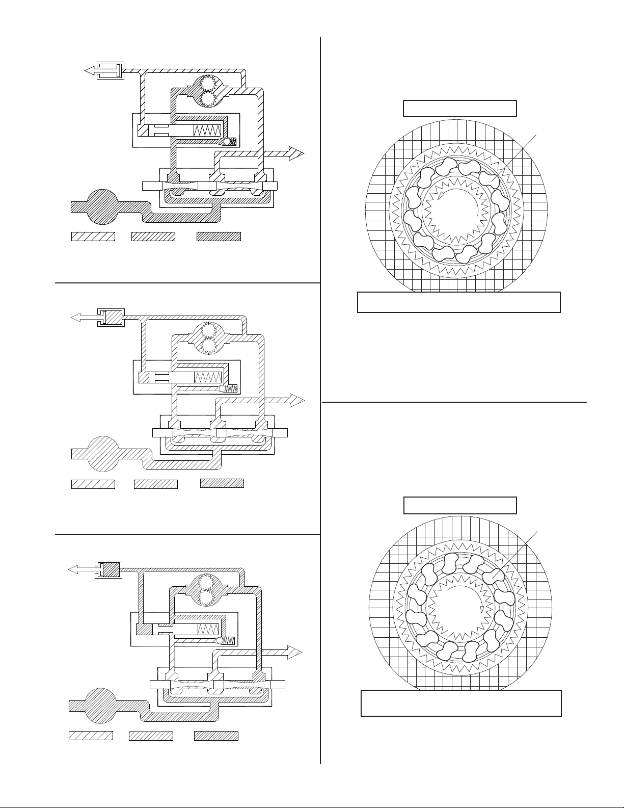
The brake valve is basically a counterbalance valve with
better metering characteristics for load control. It contains
a check valve to allow free oil flow to the motor in the haul-
in direction, and a pilot operated, spring-loaded spool
valve that blocks the flow of oil out of the motor when the
control valve is placed in neutral. With the control valve
lever moved toward the pay-out direction, the spool valve
remains closed until sufficient pilot pressure is applied to
the end of the spool to shift it against the spring pressure
and open a passage. After the spool valve cracks open,
the pilot pressure becomes flow dependent and modulates
the spool valve opening, controlling the pay-out speed of
the winch. See Figures 1, 2, and 3.
The static brake system has three main components for
all winches:
1. Spring-Applied, Multiple Friction Disc Static Brake
2. Hydraulic Piston and Cylinder
3. Brake Clutch Assembly
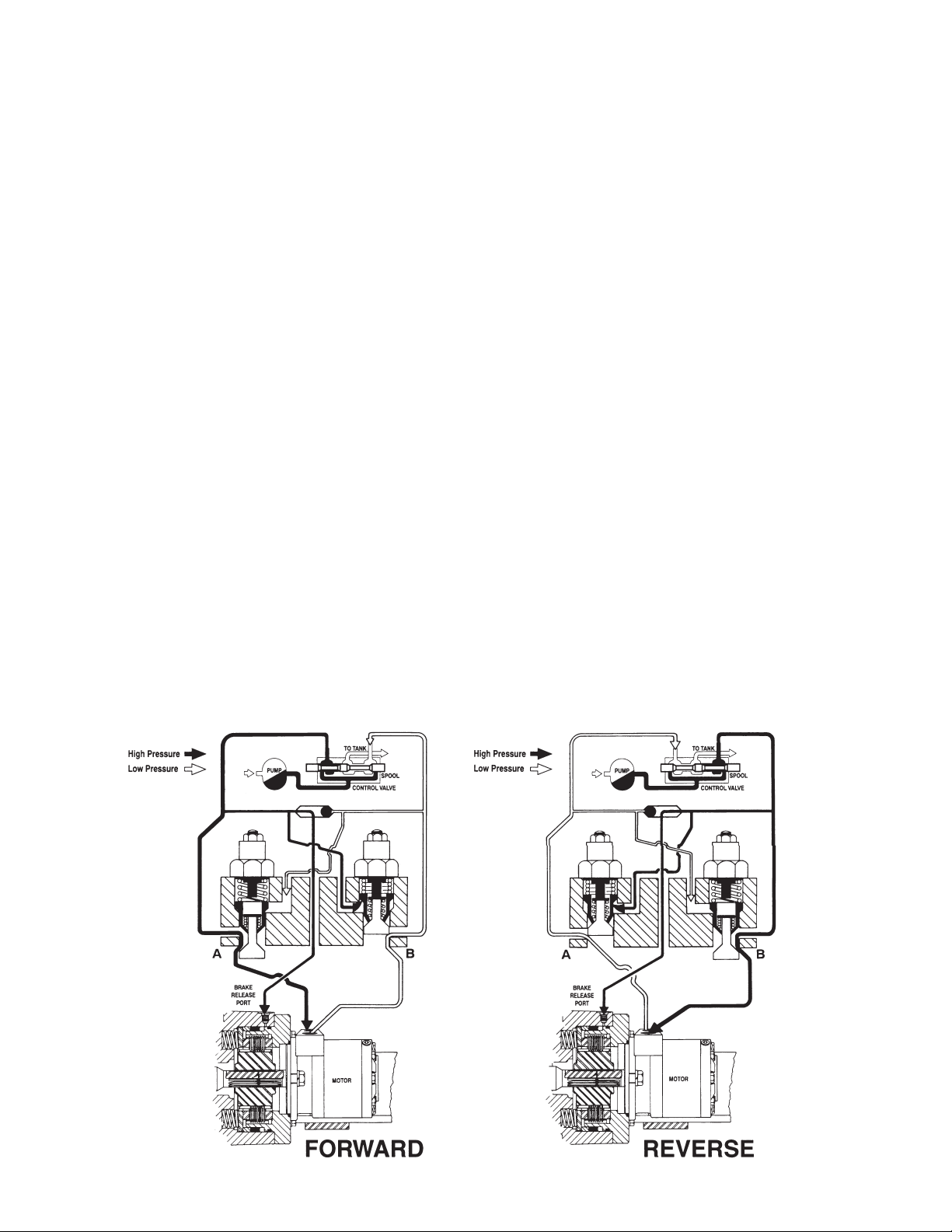
The static brake is released by the brake valve pilot pres-
sure at a pressure lower than that required to open the
pilot operated spool valve. This sequence ensures that dy-
namic braking takes place within the brake valve, and that
little, if any, heat is absorbed by the static, friction brake.
The static friction brake is load holding brake only, and has
nothing to do with dynamic braking or the rate of descent
of a load.
The brake clutch assembly is splined to the primary sun
gear shaft between the hydraulic motor and primary sun
gear. It will allow this shaft to turn freely in the direction
to haul-in a load, and locks up to force the brake discs to
turn with the shaft in the pay-out direction. See Figures 4
and 5.
The hydraulic brake cylinder, when pressurized, will re-
lease the spring pressure on the brake discs, allowing the
discs to turn freely.
7
Motor
Control Valve
Pump
To Tank
Brake Valve
Static Brake
Medium
Pressure
Low
Pressure
High
Pressure
Figure 1
Figure 2
Figure 3
Motor
Control Valve
Pump
To Tank
Brake Valve
Static Brake
Medium
Pressure
Low
Pressure
High
Pressure
Motor
Control Valve
Pump
To Tank
Brake Valve
Static Brake
Medium
Pressure
Low
Pressure
High
Pressure
Sprag Cams
Figure 4
Static Friction Brake Applied
Permits free shaft rotation while hoisting
Hoisting
Sprag Cams
Figure 5
Static Friction Brake Applied
Load attempts to rotate shaft in opposite direction
Brake clutch locks sun gear shaft to friction brake
Stopped,
Holding
Load
HOISTING
START OF LOWERING
(Static Brake Released but Brake Valve Not Open)
LOWERING
8
DESCRIPTION OF OPERATION
(Winch with Solid Brake Coupling)
The HP35A winch comes in two basic configurations:
1. Winch has an overrunning clutch and the brake is re-
leased during reel-out only.
2. Winch has a solid brake coupling and the brake is
released during reel-in and reel-out. Generally, the
winches with a solid brake coupling will be units with
extension shafts.
The description of operation for both configurations is in-
cluded in this manual.
The HP35 winch consist of the following sub-groups:
1. Hydraulic Motor and Brake Valve
2. Static Brake Assembly
3. Planetary Gear Set
4. Cable Drum, Drum Shaft and Bearings
5. Drum Clutch
6. Bumper Assembly with Fairlead
7. Extension Shaft Option
The static brake assembly is a multiple disc, bathed in oil
(wet) brake pack that is spring-applied and hydraulically
released. It is equipped with a solid brake hub that couples
the motor shaft to the primary planetary sun gear. When-
ever the winch is stopped with the controls in neutral, the
static brake is applied holding the hydraulic motor shaft
firm and not allowing the cable drum to rotate in either
direction.
During operation, the static brake must be hydraulically re-
leased when the winch is operated in either direction. With
the control lever moved in either the REEL-IN or REEL-
OUT direction, hydraulic oil is piloted to the brake release
piston and routed to the motor at the same time. Oil flow
out of the motor is initially blocked by the active counter-
balance cartridge.As hydraulic oil pressure increases, the
static brake releases. At this time, oil flow out of the mo-
tor is still blocked. As pressure continues to increase, the
cartridge is piloted open allowing the motor shaft to ro-
tate. This sequence ensures the static brake is completely
released before any rotation occurs, resulting in minimal
wear of the friction discs.
The extent to which the cartridge opens determines the
amount of oil allowed to flow through it, and thus the
speed of the cable drum. Increasing the flow of oil to the
winch motor will cause the pressure to rise and the open-
ing in the cartridge to enlarge, allowing more oil to flow
and increasing the speed of the winch. Decreasing this
flow causes the pressure to lower, decreasing the opening
in the cartridge and slowing the speed of the winch. When
the control valve is returned to center, or neutral, and oil
flow is stopped, motor shaft rotation stops and the static
brake is fully applied by the force of the brake springs.

9
WINCH INSTALLATION
The standard HP Series winches are configured for bed
mount on a truck with the motor end to the passenger side
of the vehicle and the wire rope overwound on the drum.
Any other installation arrangement will require modifica-
tions to the winch before installation.
Headache racks or other protective structures designed
to protect the winch, truck, cab, and vehicle occupants
should be designed to enable easy access and servic-
ing of the winch. Braden recommends using a structure
designed to be easily removed should the need arise to
disassemble the winch for servicing.
1. The winch must be mounted to a flat, rigid surface
which will not flex under load. The mounting surface
must be flat within .020 in. (.05 mm) between mount-
ing fasteners. If necessary, use shim stock to ensure
proper mounting.
2. The centerline of the cable drum must be horizontal
and mounted perpendicular to the direction of pull. The
fleet angle, or the angle created from an imaginary line
from the center of the cable drum to the load or first
sheave and from this load point back to the drum bar-
rel intersection with the drum flange, must not exceed
1½°. Fleet angles in excess of 1½° will create uneven
spooling resulting in rapid drum or wire rope wear.
3. Grade 8, or better, fasteners are recommended for
mounting fasteners.
4. The winch base angles must be mounted securely to
the vehicle frame in a manner acceptable to the vehicle
manufacturer.Any frame adapter brackets used should
be bolted to the winch base angles as close to the gear
housing and bearing leg assemblies as possible. This
will ensure the greatest strength while minimizing dis-
tortion. Consult vehicle manufacturer before making
any modifications to the vehicle frame.
5. Hydraulic lines and components to operate the winch
should be of sufficient size as to minimize the back-
pressure at the hydraulic motor work ports.
For conventional gear type motors, backpressure at full
flow should NOT exceed 100 PSI (690 kPa) for maxi-
mum motor shaft seal life. If high backpressures are
encountered, the motor case drain can be connected
direct to the reservoir. For backpressures in excess of
100 PSI (690 kPa), contact PACCAR Winch Division
Technical Support.
Winches equipped with Rineer vane type or piston
type motors MUST be limited to 35 PSI (240 kPa)
backpressure.
6. The winch directional control valve MUST be a three-
position, four-way valve without detents and with a
spring-centered motor spool, such that the valve re-
turns to the center (Neutral) position whenever the
handle is released, and both work ports are opened to
tank (open center, open port).
7. The hydraulic oil filter should have a 10 micron nominal
rating and be a full-flow type.
8. High quality hydraulic oil is essential for satisfactory
performance and long hydraulic system component
life.
Hydraulic oils having 150 to 300 SUS viscosity at 100°F
(38°C) and a viscosity index (VI) of 100 or greater will pro-
vide good results under normal temperature conditions.
The use of oils having a high VI will minimize cold start-
up problems and reduce the length of warm-up periods.
A high VI will also minimize changes in viscosity with cor-
responding changes in temperature.
Maximum cold weather start-up viscosity should not ex-
ceed 5000 SUS with a pour point of at least 20°F (11°C)
lower than the minimum expected temperature.
Under continuous operating conditions the temperature of
the oil at any point in the system should not exceed 180°F
(82°C). 120° to 140°F (49° to 60°C) is generally consid-
ered optimum.
In general terms; for continuous operation at ambient tem-
peratures 50° to 110°F (10° to 43°C), use SAE 20W; for
continuous operation at 10° to 90°F (-12° to 32°C), use
SAE 10W; and for applications at ambient temperatures
below 10°F (-12°C), contact the PACCAR Winch Division
Product Support Department. NOTE: The use of multi-
viscosity oils is not recommended.
9. Maximum air pressure of 130 psi for clutch and brake
air cylinders.
Flexing or uneven mounting surfaces will produce in-
ternal winch distortion which may result in rapid com-
ponent wear, overheating, poor winch performance
or an improperly engaged drum clutch which may be-
come disengaged and result in dropped loads or loss
of load control causing property damage, severe injury
or death.
DO NOT use a control valve with any detents or latch-
ing mechanism that will hold the control valve in an ac-
tuated or running position when the operator releases
the control lever. Use of the wrong type of control valve
could lead to unintentional operation of the winch, which
could result in property damage, injury or death.

10
TYPICAL HYDRAULIC CIRCUITS
NOTE: The hydraulic circuits shown below are representative of typical HP35A winches with single and two-speed hy-
draulic motors and brake valves. Options and accessory equipment may result in changes to the circuits shown. If there
are any questions regarding the hydraulic circuit, contact the PACCAR Winch Division Product Support Department.
(ALWAYS have the winch model and serial number available when contacting PACCAR Winch Division.)
2-Speed Hyd. Motor Sub-Assy Control Circuit
(”A” Port Toward Flange)
ITEM 7
WINCH
BRAKE
LOWER ITEM 13
CASE DRAIN
(CUSTOMER)
HOIST
BRAKE
VALVE
CHECK
VALVE
12V DC
SOLENOID
2-SP HYD MOTOR
2 - SPEED
SELECTOR
VALVE
P
T
TA
G
P2
P1
BR
BA
Two Speed
30 85 86 87 87A
Electric Shift Circuit
Hella 87499 Relay
(or equivalent -
12 Volt DC,
40 Amp, SPDT)
+12 VDC Power
Normally Open SPST Switch*
(Engaging Switch Shifts Motor
to High Speed) Motor
Solenoid
* DO NOT use a
momentary contact
switch. This type of
switch will return to the
open position when
released, shifting the
motor back to low speed.
12
3
1. Ground
2. Empty
3. Apply 12V DC power to shift
motor to High Speed
NOTE:
Terminals 1 and 3 may be
reversed since the solenoid is
not polarity sensitive.
WINCH ASSEMBLY
W/BRAKE VALVE
& STATIC BRAKE
WINCH BRAKE
BR
BRAKE
VALVE
DR
CONTROL
VALVE
PUMP
WINCH CONTROL CIRCUIT
EXTERNAL CASE DRAIN REQ’D
X
Single Speed

11
AB
WINCH
BRAKE
BR
Low Speed High Torque Motor
Case drain required if back pressure is greater than 100 psi.
12
WIRE ROPE INSTALLATION
Winches are rated at bare drum line pull, meaning the maximum load capability will be reached on the first layer of wire
rope.As the cable drum fills and adds layers of wire rope, the line pull will decrease (loss of leverage) as the line speed
increases (larger circumference). Therefore, it is best to install the minimum length of wire rope possible for your ap-
plication so the winch will operate on the lowest layers, delivering the maximum load capability.
Use of larger diameter wire rope will not always increase strength as the larger wire rope may be more prone to bending
fatigue failure due to the drum diameter. Consult your wire rope supplier for their recommendations regarding the best
wire rope and rigging for your application.
Winch wire rope anchors or U-Bolts are NOT intended to hold rated loads. Winch loads applied directly to the cable
anchor may cause the wire rope to pull free and result in sudden loss of load control and cause property damage,
injury, or death. A minimum of five (5) wraps of wire rope must be left on the drum barrel to achieve rated load.
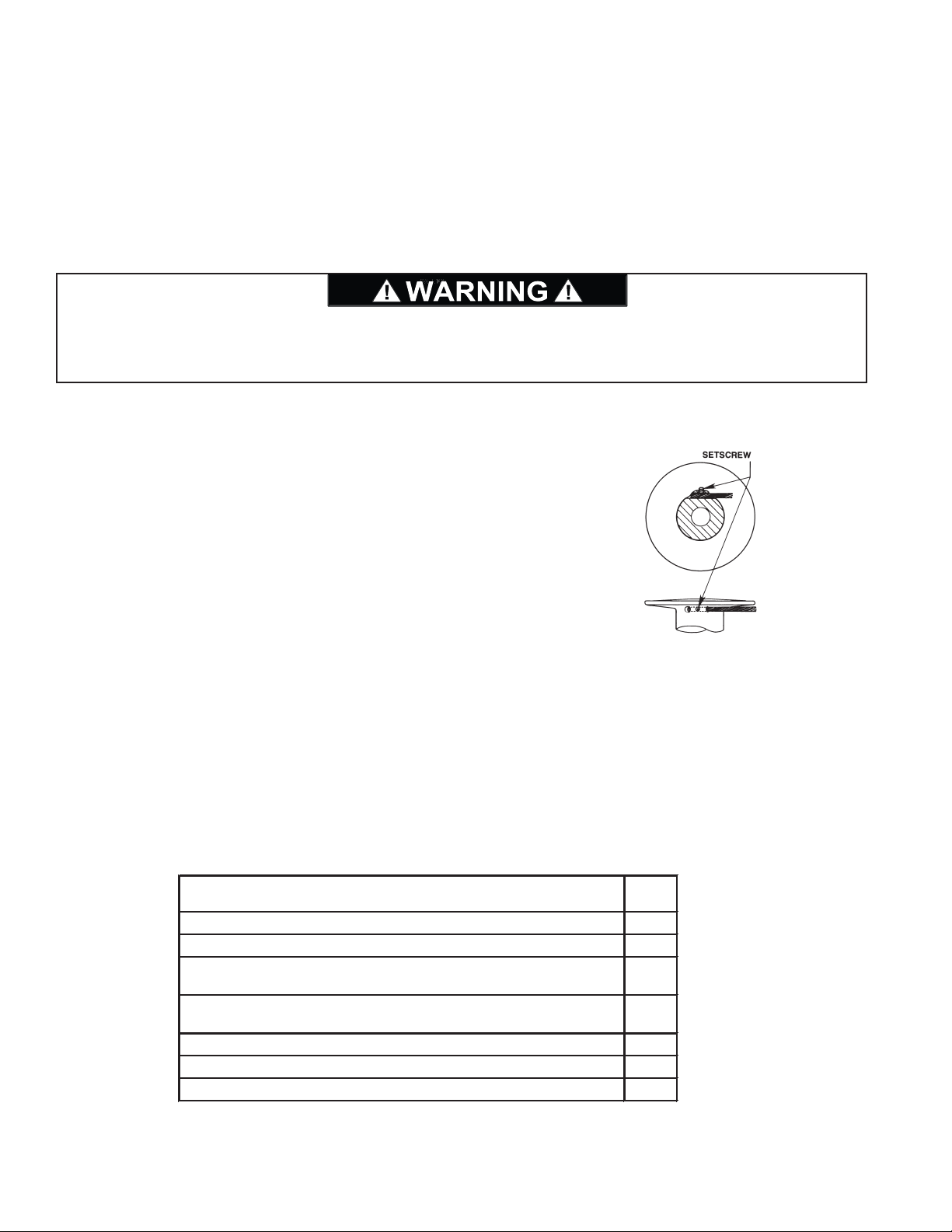
INSTALLATION OF SET SCREW CLAMPS:
Prepare the end of the wire rope as recommended by the wire rope manu-
facturer. Insert the proper size rope through the anchor hole until it is almost
flush with the other end.Apply “Loctite” or equivalent removable thread locking
compound to the clean, dry threads of the setscrew and install the setscrew.
Tighten the setscrew until the rope is slightly deformed and held securely.
PRE-DELIVERY CHECKLIST
Before releasing the winch to the end user, the following checklist should be reviewed and each item verified.
INSPECTION
Check gear oil and refill as needed.
Lubricate all grease fittings.
Inspect winch mounting fasteners and torque
as required.
Check for loose or missing bolts, pins, keepers
and cotter pins. Replace as needed.
Check controls - adjustment and operation.
Verify winch operating pressure and flow.
Inspect for external oil leaks. Repair as needed.
3

13
WINCH OPERATION
The following warnings and instructions are basic to safe
winch operation. Please read them carefully and follow
them any time the winch is in use. These instructions are
provided in addition to any information provided by the
Original Equipment Manufacturer of the platform the winch
is mounted on. Equipment operators should be completely
familiar with the overall operation of the vehicle to which
the winch is installed. If you have any questions concern-
ing the safe operation of this winch or the equipment to
which it is mounted, contact the equipment manufacturer
that installed the winch, or the PACCAR Winch Division
Product Support Department, as previously defined.
The winch directional control valve, described earlier,
controls haul-in and pay-out functions of the winch. Mov-
ing the control lever in the haul-in direction will cause the
winch to pull in the load toward the vehicle. Moving the
control lever in the pay-out direction will cause the winch
to feed wire rope off the drum.
NOTE: During winching operations, it is recommended to
operate the vehicle engine or hydraulic pump drive at high
idle RPM and use the winch control valve to control oil
flow, and thus winch line speed as needed.
Position the vehicle such that the centerline of the winch
drum is perpendicular to the winch load whenever pos-
sible. The wire rope fleet angle must not exceed 1½°. If
the fleet angle exceeds 1½°, the wire rope will not spool
correctly, eventually resulting in damaged wire rope and
prematurely worn winch components.
Either power out the wire rope using the hydraulic system,
or disengage the drum clutch and pull the wire rope off the
drum by hand (freespool).
Securely attach the wire rope to the load in such a manner
as to avoid damaging the load or rigging. Fully engage the
drum clutch (see Drum Clutch Operation).
Observe the winch operation carefully to make certain all
ground personnel remain clear of the wire rope and load,
and that the load does not shift, which may require reposi-
tioning the wire rope or the vehicle.
Once the load is positioned properly, move the lever back
to neutral to stop the winch. Secure the load as required.
Pay out just enough wire rope to remove all tension on the
cable drum. Disengage the drum clutch and disconnect
the wire rope from the load.
Re-engage the drum clutch. Ensure the drum clutch is fully
engaged. (See drum clutch operation on page 14.)
Wind the wire rope onto the cable drum while maintaining
the minimum fleet angle and sufficient tension to allow the
wire rope to spool properly, being careful to keep hands
and clothing away from the cable drum and/or fairlead roll-
ers.
Ground personnel MUST stay in view of the operator
and clear of the load and cable drum at all times. DO
NOT allow personnel near the winch line while under
tension. DO NOT allow personnel near the cable drum
during winch operation. DO NOT allow personnel to be
in line with the load. DO NOT allow personnel to stand
under a suspended load. A safe distance of 1 1/2 times
the working length of the cable should be maintained by
ground personnel. A broken wire rope and/or lost load
may cause property damage, injury or death.
Failure to properly warm up the winch, particularly un-
der low ambient temperature conditions, may result in
temporary brake slippage due to high back pressures
attempting to release the brake, which may result in
property damage, injury or death.
Failure to use the proper type and viscosity of planetary
gear oil may contribute to intermittent brake clutch slip-
page which could result in property damage, injury or
death. Some gear lubricants contain large amount of
EP (extreme pressure) and anti-friction additives which
may contribute to brake slippage and damage to brake
friction discs or seals. Oil viscosity with regard to ambi-
ent temperature is also critical to reliable brake opera-
tion. Testing indicates that excessively heavy or thick
gear oil may contribute to intermittent brake slippage.
Use only approved gear oil. (See page 45.)
If oil is leaking from the vent relief valve (see drawing on
page 19) or winch, immediately remove the winch from
service and determine the cause.
High pressure in the winch may result in property dam-
age, personal injury, or death.
14
DRUM CLUTCH OPERATION
Visually ensure that the drum clutch is fully engaged and
the clutch control lever is at full travel and locked in its de-
tent BEFORE attempting to use the winch under load.
NOTE: Actuation of the drum clutch is typically accom-
plished using either air cylinder controls or some form of
mechanical control (i.e. push-pull cable, mechanical link-
ages, etc.). Any means used to control the drum clutch
must allow full travel of the lever without binding the clutch,
or should include locking detents at each position.
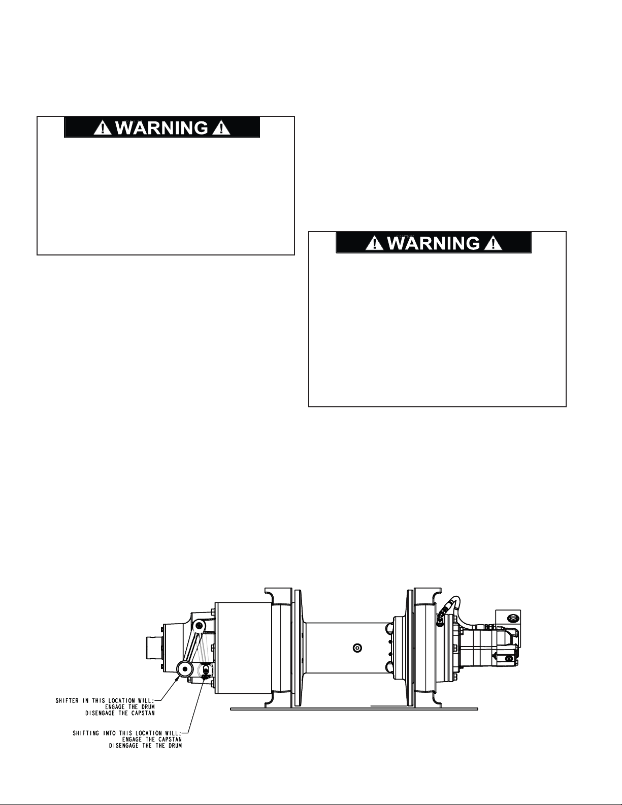
To ENGAGE the drum clutch
(Disengage the Capstan):
1. Insure the winch motor is stopped and there is no load
on the wire rope. The prime mover must be stopped in
neutral and the parking brake must be set.
2. Move the clutch control lever fully into the “Engage”
position. If the lever will not settle into the fully engaged
position, the clutch is not fully engaged. At this point,
it may be necessary to MANUALLY rotate the cable
drum slightly in either direction to align the clutch collar
splines with the drum driver splines, while continuing
to hold slight pressure on the control lever. Once the
clutch collar splines are properly aligned, the clutch
should easily engage fully with the clutch plate on the
cable drum.
To DISENGAGE the drum clutch
(Engage the Capstan):
1. Insure the winch motor is stopped and there is no load
on the wire rope. The prime mover must be stopped in
neutral and the winch parking brake set.
2. Move the control lever fully into the “Drum Disengage”
position. If the control lever has any resistance to shift,
the cable drum may be MANUALLY rotated in the di-
rection to haul-in wire rope to align the clutch collar
splines and allow the clutch to properly disengage from
the drum and engage the capstan shaft.
The winch capstan rotates approximately 6 times faster
than the winch drum because the output planet carrier re-
duction is not used.
DO NOT move the load, the winch, or the winch plat-
form BEFORE making certain the drum clutch is set to
“ENGAGE” and the clutch is fully engaged. A partially
engaged drum clutch may “jump out” of engagement. A
load on the winch line may prevent a partially engaged
clutch from disengaging, but any change in load condi-
tion may allow the clutch to become disengaged unex-
pectedly. This action may cause a loss of load control
which could result in property damage, injury or death.
DO NOT attempt to engage the drum clutch while the
cable drum is rotating. DO NOT attempt to disengage
the drum clutch with a load applied to the wire rope. DO
NOT use “cheaters” to extend the shift lever length or
other means to apply undue force on the lever. Engag-
ing or disengaging the drum clutch while the cable drum
is rotating or under load, or the use of undue force, may
result in damage to the drum clutch components. Dam-
aged drum clutch components may allow the drum
clutch to become disengaged under load, and cause a
loss of load control, which could result in property dam-
age, injury or death.

15
Copies of the Warning Label shown above are available through all Braden dealers. Have your dealer order part num-
ber 100600. It is a self-adhesive weather-resistant vinyl label that we recommend be installed near the winch controls
of all Braden winches with a drum clutch.

16
CAPSTAN USE
Presently, Braden uses only one type of capstan – the quick disconnect bayonet type. Other types have been used
previously, including a bolt-on type.
To install the bayonet type capstan, push the capstan onto the extension shaft, against spring tension, then turn the
capstan counter-clockwise (CCW) to the stop. Release the capstan and verify the spring has pushed the capstan
back outward into the “lock” position.
HP35 winches use a load holding brake that must be released when the winch is operated in both directions. This al-
lows the rope to be wound around the capstan in either direction during capstan use.
• BEFORE installing a bayonet type capstan, make certain the spring is properly located in the bore. The spring
holds the capstan in the “lock” position on the extension shaft. If the spring is missing or omitted, the capstan may
come off the shaft and cause a sudden loss of load control which may result in property damage, injury or death.
Also, closely inspect the edges of the of the lock pocket to insure they are still sharp and not rounded from use.
A badly worn lock pocket may prevent the capstan from locking securely to the shaft, which could allow the cap-
stan to come off the shaft and cause a sudden loss of load control which may result in property damage, injury or
death.
• Make certain the vehicle is positioned such that the load line and hand line are perpendicular to the capstan barrel.
DO NOT allow rope to pull against either flange of the capstan, as the rope may get damaged or “jump” over the
flange and cause a sudden loss of load control which may result in property damage, injury or death.
• If a bolt-on type of capstan is used, make certain that a ¾ in. X 5-¼ in. Grade 8 (M20 X 133 mm, Class 10.9) cap-
screw and self-locking hex nut are used. A soft bolt or pin may shear off and cause a sudden loss of load control
which may result in property damage, injury or death.
Exposed areas of capstans and extension shafts are extremely dangerous. Clothing and other items may become
entangled and wrapped around the rotating shaft. Install appropriate guarding to prevent any part of the body or
clothing from making contact with the shaft when it is rotating. Failure to provide adequate guarding could result in
property damage, injury or death.
Spring
Sharp Corner
of Lock-Pocket
“GOOD”
Spring Missing
OR
Worn Corner of
Lock-Pocket
“DO NOT USE”

17
AUXILIARY RIGGING
Snatch Block
An auxiliary sheave, or snatch block, increases the versa-
tility of the winch, and is highly recommended in the fol-
lowing applications:
When fleet angles exceed 1½°;
When winch loads exceed the safe winch or wire rope
capacity;
When slower line speeds are required for precise load
control.
Securely attach the snatch block to the anchor point fol-
lowing the block manufacturer’s recommendations.
Tree Protector
If the wire rope or a snatch block must be anchored to a
tree or other structure for recovery purposes, a heavy ny-
lon web sling of proper capacity rating should be used to
avoid causing serous damage to the tree.
Apoorly attached or undersized snatch block may break
loose from the anchor point and cause a sudden loss of
load control, which may result in property damage, in-
jury or death.
18
PREVENTIVE MAINTENANCE
A regular program of preventive maintenance for your
winch is required to minimize the need for emergency ser-
vicing and will promote safe, reliable winch operation.
The user of PACCAR Winch products is responsible for
winch inspection, testing, operator training and the main-
tenance noted below, with frequency dependent on the
severity of the winch duty cycle and the thoroughness of
the preventive maintenance program.
Field experience, supported by engineering testing, indi-
cate the two service procedures listed below are the most
critical to safe, reliable winch operation and MUST be ob-
served.
• Recommended Gear Oil Changes
• Use of Proper Gear Oil – recommended type for pre-
vailing ambient temperatures and additives.
Recommended Preventive Maintenance Intervals:
Daily (when winch is in use)
1. Inspect the wire rope and rigging for broken wires or
other damage, as recommended by the wire rope and
rigging manufacturer(s).
2. Carefully inspect the drum clutch and adjust the shift
mechanism as required to ensure the clutch can be
fully engaged and disengaged. (Refer to “Drum Clutch
Operation”.)
3. Check for external oil leaks – both hydraulic and gear
oil – and repair as required. This is extremely important
due to the accelerated wear that can be caused by in-
sufficient lubrication within the winch. Gear oil must be
maintained at the proper level. Use only recommended
lubricants. (See “Recommended Lubricants” in this
manual.)
4. Check hydraulic motor plumbing for damage, such as
chafed or deteriorating hoses, and repair as needed.
5. Visually inspect for loose or missing bolts, pins, keep-
ers or cotter pins, and tighten or replace as needed.
Weekly
1. Perform all daily inspections.
2. Check gear oil level, and refill as needed with the rec-
ommended lubricant.
3. Lubricate the grease fittings on the bearing leg, cable
drum ends and clutch. On some winches, you will have
to disengage the clutch to gain access to the drum
bushing grease fitting on the clutch end of the drum.
Use a high-quality, moly-type grease, with a rating of
NLGI-2 or better.
4. Inspect the gear housing breather to ensure the fitting
is not clogged with dirt or grease. Clean or replace as
needed.
5. Inspect all winch mounting fasteners. Retighten or re-
place as required.
6. Inspect any structural welds, and repair as needed.
Monthly
1. Perform all daily and weekly inspections.
2. Inspect the drum clutch and clutch plate to ensure the
negative draft angle is clearly evident. Replace worn
clutch components as required. (Refer to “Drum Clutch
Operation” in this manual.)
3. Check the hydraulic system relief valve setting to en-
sure proper performance and protection of hydraulic
components. Adjust or repair as required.
4. Inspect hydraulic system filters and strainers. Follow
the system manufacturer’s service recommendations
for repair or replacement.
Yearly
1. Perform all daily, weekly and monthly inspections.
2. Replace gear oil.
NOTE: If the winch is used in excess of 50 hours per
week, the gear oil should be changed every 6 months.
NEVER attempt to service a winch with the prime mover
running as accidental engagement may result in prop-
erty damage, injury or death.
Make certain ALL load is removed from the wire rope
and winch cable drum BEFORE servicing the winch.
A loaded wire rope may rapidly and unexpectedly un-
spool, resulting in property damage, injury or death. DO NOT use the winch if the negative draft angle on
the clutch is not present or is worn straight, or if the
clutch plate edges are rounded or chipped. A defective
drum clutch may suddenly become disengaged causing
a loss of load control, which may result in property dam-
age, injury or death.
Hot oil can cause severe injury. Make certain the oil has
cooled to a safe temperature before servicing.
Any problems identified must be corrected before the
winch is returned to service. Failure to correct may re-
sult in property damage, personal injury, or death.

19
Daily Weekly Monthly Yearly
Inspect wire rope and rigging XXXX
Inspect drum clutch and shift
mechanism for proper engagement
XXXX
Inspect for external oil leaks XXXX
Check for damaged hoses / lines XXXX
Check for loose or missing bolts,
pins, keepers, or cotter pins
XXXX
Check gear oil level / refill XXX
Lubricate grease fittings XXX
Inspect breather fitting XXX
Inspect winch mounting fasteners -
torque as required
XXX
Inspect structural welds XXX
Check hydraulic relief valve setting XX
Inspect hydraulic filters / strainers XX
Replace gear oil
See Notes
(1) and (2)
X
NOTES:
(1) Change the gear oil after the first 100 hours or 30 days of use,
whichever occurs first.
Inspection Interval
Inspection Performed
(2) For winch operation in excess of 50 hours per week, oil changes should
occur every 6 months instead of yearly.
OIL DRAIN
PLUG
OIL FILL
AND VENT
REEL OUT
PORT
OIL LEVEL
SIGHT GAUGE

20
11.9
Low Speed
High Torque
Motor
10.2/5.1
2-Speed
Gear Motor
11.0
Gear Motor
Rated Bare Drum Line Pull
35,000 Lb
(15,905 kg)
35,000 Lb
(15,905 kg)
35,000 Lb
(15,905 kg)
Bare Drum Line Speed - Single Speed
27 fpm
(8 mpm)
57 fpm
(17 mpm)
52 fpm
(16 mpm)
Cable Drum Diameter
6.06 in.
(154 mm)
6.06 in.
(154 mm)
6.06 in.
(154 mm)
Cable Drum Flange Diameter
14.0 in.
(356 mm)
14.0 in.
(356 mm)
14.0 in.
(356 mm)
Distance Between Flanges
12.37 in.
(314 mm)
12.37 in.
(314 mm)
12.37 in.
(314 mm)
Wire Rope Capacity - 3/4" (20 mm)
187 ft.
(57 m)
187 ft.
(57 m)
187 ft.
(57 m)
Overall Gear Ratio 35:1 35:1 35:1
Maximum Pressure
2,578 PSI
(178 Bar)
2,754 PSI
(190 Bar)
2,509 PSI
(173 Bar)
Maximum Flow
30 GPM
(113 lpm)
60 GPM
(227 lpm)
60 GPM
(227 lpm)
Capstan Rating (7" Capstan)
3,200 Lb
(1,450 kg)
N/A N/A
Capstan Speed 185 ft
(56.4 m) N/A N/A
Winch Weight
650 Lb
(295 kg)
650 Lb
(295 kg)
650 Lb
(295 kg)
- Add for Extension Shaft
90 Lb
(41 kg) N/A N/A
Gearbox Oil Capacity 10.5 pt
(5.0 L)
10.5 pt
(5.0 L)
10.5 pt
(5.0 L)
Capstan Ratio 5.4:1 N/A N/A
HP35A
SPECIFICATIONS
Table of contents
Other BRADEN Winch manuals


Popular Winch manuals by other brands

Maxwell
Maxwell VWC 2500 manual

AL-KO
AL-KO 351 Plus Translation of the original operating instructions

Ingersoll-Rand
Ingersoll-Rand force5 FA5A-SXK1 Parts, operation and maintenance manual

Mile Marker
Mile Marker PEC8 Installation and operator's manual

Champion Power Equipment
Champion Power Equipment 13050 Owner's manual & operating instructions

Multi
Multi 3000 Instructions for use and maintenance


