8
HL-Series Tankless Heater Installation
3/29/2018 Bradley • 215-1823 Rev. F; ECN 18-17-017
Electric Installation
3
B
NEMA 1: A pre-cut hole is already sized for
conduit connection. Skip to step C.
NEMA 4/4X: Using a hole punch, cut a hole
the proper size for conduit connection; large
enough for the wire size for each heater. The
connectors need to be rated NEMA4/4X to
ensure proper sealing of the enclosure.
AFor NEMA 1 enclosures, remove the four screws
and take the bottom cover off. For NEMA 4/4X
enclosures, open the enclosure door.
CRun wires through the appropriate size conduit.
DConnect wires to the system terminal block
inside the enclosure.
EConnect the ground wire to the stud provided
with the “Ground” label beneath it.
NOTICE! Any option that requires field wiring must
be done with a wire rated for the maximum
voltage of the heater.
NOTICE! Use a three for a single phase or a four core
cable for three phase from an approved
isolating two or three pole switch or circuit
breaker to the terminal block of the heater.
NOTICE! Make sure the electrical cable is the correct
size to carry 100 % of the full load current.
See table for proper wire sizes.
WARNING Install product to rated line voltage in
accordance to current local and national
codes and regulations.
WARNING All Keltech heaters must be fused in
accordance with National Electric Code
(NEC) for the full load amperage listed
on the nameplate rating for each heater.
WARNING Failure to properly ground the unit(s) per
the National Electric Code could result in
injury or death.
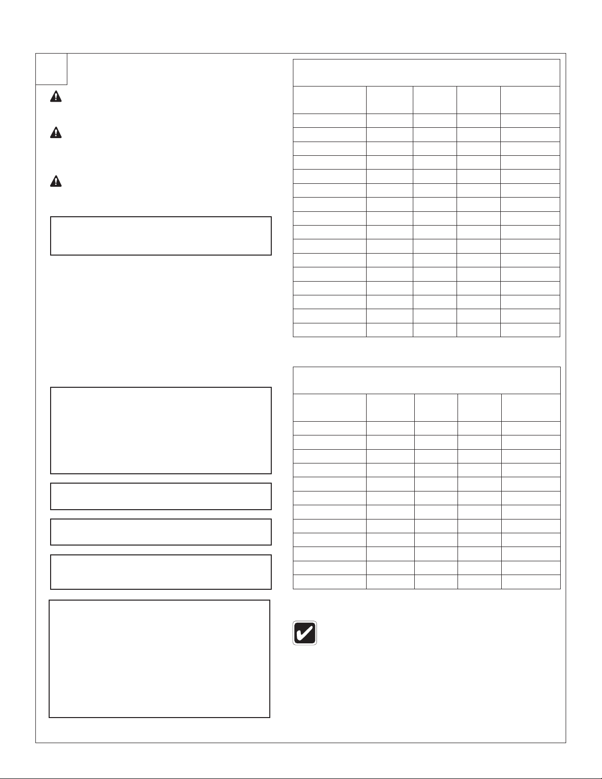
ELECTRICAL SPECIFICATIONS FOR HEATER
(Single Phase)
Model Voltage Amps kWatts Min Wire
Size
HL060/480D 480 13 6 12 AWG*
HL180/480D 480 38 18 6 AWG*
HL060/415D 415 6 4 12 AWG*
HL180/415D 415 19 13 10 AWG*
HL060/380D 380 6 4 12 AWG*
HL180/380D 380 17 11 12 AWG*
HL060/277D 277 22 6 10 AWG*
HL180/277D 277 65 18 3 AWG*
HL050/240D 240 21 5 10 AWG*
HL060/240D 240 25 6 8 AWG*
HL100/240D 240 42 10 6 AWG*
HL180/240D 240 75 18 3 AWG*
HL050/208D 208 24 5 10 AWG*
HL060/208D 208 29 6 8 AWG*
HL100/208D 208 48 10 4 AWG*
HL180/208D 208 87 18 3 AWG*
* Based on the NEC Table 310.15 for 75°C insulated copper wire @ 30°C
Ambient. Aluminum wire requires larger gauges.
ELECTRICAL SPECIFICATIONS FOR HEATER
(Three Phase)
Model Voltage Amps kWatts Min Wire
Size
HL103/480D 480 13 10 12 AWG*
HL183/480D 480 22 18 10 AWG*
HL103/415D 415 10 7 12 AWG*
HL183/415D 415 19 13 10 AWG*
HL103/380D 380 10 6 12 AWG*
HL183/380D 380 17 11 12 AWG*
HL153/240D 240 36 15 6 AWG*
HL183/240D 240 43 18 6 AWG*
HL153/208D 208 42 15 6 AWG*
HL183/208D 208 50 18 4 AWG*
HL103/208D 208 28 10 8 AWG*
HL253/480D 480 30 25 8 AWG*
Not all available (optional) voltages are listed in table.
F
If unit is ordered with a D1 or DC controller option,
the DB9 connector for hookup on a standard
unit is located on the upper left/hinge side of the
cabinet. Please review the appropriate Special
Installation & Operation Instruction section for
information regarding controller programming and
wiring. Proceed to the Start Up Checklist once
the steps in the Special Installation & Operation
Instructions section have been completed or
if you do not have this option.