Sumitomo Drive Technologies PARAMAX SFC Series User manual

These products should be handled, installed, and maintained by trained technicians.
Carefully read the maintenance manual before use.
Oil is removed from these products before shipment. Supply oil according to the
maintenance manual before operation.
A copy of this maintenance manual should be sent to the actual user.
This maintenance manual should be kept by the user for future reference.
PARAMAX®
SFC Series
for Cooling fan
No.GM2201E-5Maintenance Manual
CAUTION


1
(Safety and other precautions)
Carefully read this maintenance manual and all accompanying documents before use (installation, operation,
maintenance, inspection, etc.). Thoroughly understand the machine, information about safety, and all precautions for
correct operation.
Maintain this manual for future reference.
Pay particular attention to the "DANGER" and "CAUTION" warnings regarding safety and proper use.
DANGER : Improper handling may result in physical damage, serious personal injury and/or
death.
CAUTION : Improper handling may result in physical damage and/or personal injury.
Matters described in CAUTION may lead to serious danger depending on the situation. Be sure to observe
important matters described herein.
DANGER
●Transport,installation,plumbing,operation,maintenance,andinspectionsshouldbehandledbyproperlytrained
technicians ; otherwise, injury or damage to the machine may result.
●Donotdisassemblethese productsduringoperation.Evenifitisatrest,donotdisassembleanypartsother
than the oil inlet/outlet when the input/output shafts of these products are connected to a motor or other mating
machines; otherwise falling or operation out of control due to disengagement of gears, as well as death, injury, or
damage to the machine may result.
CAUTION
● Theunitshouldbeoperatedonlywithinitsdesignandperformancespecications;otherwise,injuryordamageto
a system may occur.
● Keep handsandall foreign objectsfrom the internalmoving partsof the unit; otherwise,injuryor damage toa
system may occur.
● Damagedunitsshouldbetakenoff-lineandnotputbackinoperationuntilproperlyrepaired.
● Anymodicationsoralterationsofanykind,totheunit,willvoidthewarrantyandallsubsequentclaims.
● Donotremovetheratingplate.
Oil has been removed from these products before shipment from our factory, so supply recommended oil before use.
CONTENTS
Safety and other precautions......................1 8. Operation....................................................7
1. Inspection upon delivery.............................2 9. Daily inspection and maintenance..............8
2. Storage.......................................................3 10. Troubleshooting..........................................9
3. Transport ....................................................3 11. Disassembly/reassembly and disposal.......9
4. Installation ..................................................3 12. Construction drawing................................10
5. Coupling with other machines ....................4 13.Locationsofoillleranddrainplug .......... 11
6. Lubrication..................................................5 14. Warranty ...................................................12
7. Backstop.....................................................6

2
1. Inspection upon delivery
CAUTION
● Unpacktheunitafterverifyingthatitispositionedrightsideup;otherwise,injurymayresult.
● Verifythattheunitreceivedisinfacttheoneordered.Whenadifferentproductisinstalled,injuryordamagetothe
system may result.
● Donotremovenameplate.
Upondeliveryoftheseproducts,checkthefollowing:
(1) The descriptions on the rating plate conform to your order.
(2) There were no parts damaged during transport.
(3) Allboltsandnutsarermlytightened.
If there is any doubt that the unit delivered does not conform to the one ordered, contact the nearest agent, distributor or service
ofce.
1-1) Howtochecktheratingplate
Type of reducer
Reduction ratio
Input power
Service factor
Serial number
①
②
③
U
4
5
P
0
0
0
0
0
5
R
MODEL
RATIO SF
INPUT
SERIAL NO.
k W
r/min
JAPAN
Fig. 1 Rating plate
•HavetheMODEL, RATIO and SERIALNo.informationreadywhenmakinginquiries.
1-2) Typesofreducers
Symbolsdenotethefollowing.Checkthatthetypeofreducerconformstoyourorder.
SFC
Series Size
Gear Stages
Suffix 1
Shaft
Arrangement
Suffix 2 Nominal
Ratio
Output Torque
(kNm)
R2 S
P
G
:
Splash
:
Shaft Driven
Pump
RR
6.3
7.1
8
9
10
11.2
12.5
14
16
18
045 (10.0)
055 (18.0)
060 (21.7)
065 (27.5)
070 (35.5)
075 (44.0)
SFC 065 R2 14RRSG F
Right Angle
Double Reduction
(Standard)
F
FB
N
NB
: With Cooling Fan
: With Cooling Fan &
Backstop
: No Cooling Fan
: No Cooling Fan &
With Backstop
(Standard)

3
2. Storage
When storing these products for any extended periods of time before use, consider the following important points.
2-1) Temporarystorage
(1) Store these products in a clean, dry, covered storage area.
•Donotstoretheseproductsoutdoorsorinawetlocation.
2-2) Long-termstorage
(1) TheoilsealwilldeterioratewhenexposedtohightemperaturesandUV rays.Inspectandreplacetheoilsealafter
long-termstorageifthereareanysignsofdamageorcracking.
(2) After starting theseproducts,checkthat itisfree fromabnormalsound,vibration, orheatbuild-up.(Ifanykind of
anomalyisobserved)contactthenearestagent,dealer,orserviceofceimmediately.
(3) Every2-3monthsaftershipment,operatetheseproductswiththerecommendedlubricantfor5-10minutes.Ifthis
isnotpossible,orwhentheseproductsaretobestoredformorethan6months,lltheunitwiththeproperamountof
vaporphaseinhibitor(JISNP20oritsequivalent)accordingtotheinhibitormanufacturersrecommendations.
3. Transport
CAUTION
● Exerciseamplecarenottodroptheseproductsduringtransport.Whenahangingboltorholeisprovided,besure
to use it. After mounting these products on a system, however, do not hoist the entire system using the hanging bolt
or hole.
Otherwise,personalinjuryordamagetotheequipmentand/orliftingdevicemayresult.
Beforehoisting,checktheweightwiththeratingplate,crate,performancespecications,catalog,etc.Neverhoist
these products that exceed the rating of the crane or other mechanism being used to lift it ; otherwise, injury or
damage to the unit and/or lifting device may occur.
4. Installation
DANGER
● Never standdirectly undera unitsuspended by acrane orother liftingmechanism ;otherwise personal injuryor
death may result.
CAUTION
● Donotplaceanyobjectsthatwillhinderventilationaroundtheseproducts;otherwise,coolingeffectisreduced,and
mayleadtoapossiblerehazardduetoexcessiveheatbuild-up.
● Donotsteponorhangfromtheseproducts;otherwise,injuryordamagetothemachinemayresult.
● Donottouchthekeywayattheshaftendorontheinsideoftheseproducts;otherwise,injurymayresult.
●Donotusetheseproducts for purposesotherthanthoseshownontheratingplateorinthemanufacturing
specications;otherwise,electricshock,personalinjuryordamagetotheequipmentmayresult.
● Donotplaceammableobjectsaroundtheseproducts;otherwise,remayresult.

4
4-1) Locationofinstallation
Ambient temperature : 0°C to +40°C (+32°F to +104°F)
Ambienthumidity :85%max.(Airventorairbreathermustbelocatedoutsideoffanstackwithextendedpiping)
Ambient atmosphere : There shall be no corrosive gas, explosive gas.
The installation space shall be well ventilated, and free from dust.
Location of installation : Indoors or outdoors.
• Specialspecicationsarenecessarywheninstallationconditionsareotherthanthosementionedhere.
Insuchcasescontactthenearestagent,dealerorserviceofce.
• Whenaproductismadeaccordingtospecialspecicationsforoutdooruseoruseinexplosiveenvironments, the
productcanbesafelyoperatedunderthosespeciedconditionswithoutproblem.
4-2) Installationangle
The installation angle shall be less than the limits shown in Fig.2.
0
+0.5° ±0.5°
Fig.2 Limits for installation angle
• Installtheseproductsonasufcientlyrigidbase.
• UseinstallationboltscorrespondingtoJISstrengthclass8.8oritsequivalent.Thetorqueofinstallationboltsisshown
in table1.
Table1Torqueoftheinstallationbolts
Size
Unit SFC045 SFC055 SFC060 SFC065 SFC070 SFC075
BoltSize − M24 M30 M36
Torque N·m 706 1400 2430
in·lbs 6250 12390 21510
5. Coupling with other machines
CAUTION
● IFabackstopisinstalledinthereducer,verifythattheappliedmotorrotationdirectioniscorrect.
Difference in the direction of rotation may cause injury or damage to the system.
● Installappropriateguarddevicesaroundrotatingparts;otherwise,injurymayresult.
● Whencouplingtheseproductswithaload,confirmthatthealignmenterroriswithinthespecifiedlimitsshowninthe
maintenance manual, drawings, catalog, etc. ; otherwise, damage to the system may result, due to misalignment.
● Correctlytightenrespectiveboltstothespeciedtorqueshowninthedrawing,catalog,etc.;otherwise;scattering
fragments may damage the system.
● Removethekeytemporarilyattachedtotheoutputshaftoftheseproductswhentheshaftisfree-rotating(i.e.not
loaded) ; otherwise, injury may result.

5
5-1) Installationcoupler
• Whenattachingacoupler,becarefulnottoapplyimpactforceorexcessive
thrust to the shaft ; otherwise, the bearing may be damaged.
• Shrinktorshaft-endthreadisrecommendedformounting(Fig.3)
The dimensions (A, B, and X) illustrated in Fig. 4 shall be within the tolerance
shown in Table 2.
XX
A
B
Fig. 4
6. Lubrication
6-1) Shippingcondition
• theseproductsunitsareshippedwithoutoil.Supplyrecommendedoilbeforeoperation.
6-2) Methodoflubrication
The oil splash lubrication method is used for these products.
Under certain conditions, grease or forced lubrication should be used.
(1) Splash lubrication
Standard input shaft rotating speed range 450 ~ 1800r/min.
(2) Forced lubrication
CAUTION
● For a system inwhich a lubricant motor pump is provided separately, switch on the pump motor prior to
switching on the reducer motor. This will enable proper lubrication of the bearings prior to start up.
Failure to do so may damage the unit.
Useaowswitchand/orsighttoverifythatlubricantiscirculating,andforemergencymotorstopifnecessary.
(3) Grease lubrication for bearings
Greaselubricationwillberequireddepending on an operatingcondition.Insuchcase,thelocationandnumberof
greasenipplesshouldbeconrmedinadvance.Thebearingsarepackedwithgreaseatthetimeofshipment.
Supplygreaseaccordingtotheinputspeed-every1500hourswhentherevolutionisunder750r/min,andevery1000
hourswhentherevolutionis750-1800r/min.
6-3) Selectionoflubricant
Refer to Table 3 to select mineral oil or synthetic oil.
Table 4 shows recommended lubricants.
Coupler
Shaft
Shaft end thread
Fig. 3
Table 2 Aligning tolerance for coupling
Tolerance for A
dimension 0.05mm 0.002in
Tolerance for B
dimension 0.05mm 0.002in
X dimension Speciedbycoupling
manufacturer
Table 3 Lubricant table
Ambient temperature
-20~40°C -15~40°C 0 ~ 40°C
-4~104°F 5 ~ 104°F 32 ~ 104°F
OilHeater Installed Not Installed Not Installed
Lubricant Mineral oil Synthetic oil Mineral oil
ISO*
AGMA
VG320
6EP
VG320
6S
VG320
6EP
*ISO:Kineticviscosity(mm2/s) at 40°C (104°F)

6
Table 4 Recommended lubricants
●MineralOil
Brand ARAL BP CASTROL CHEVRONTEXACO EXXON
MOBIL SHELL GULF TOTAL
FINA ELF
ISOVG320
AGMA 6EP
DEGOL
BG320
ENERGOL
GR-XP-320
ALPHA
SP320
OPTIGEAR
BM 320
TRIBOL
1100/320
GEAR
COMPOUNDS
EP320
MEROPA
WM320
MOBIL-
GEAR 600
XP 320
SHELLOMALA
S2 G 320
EPLUBRI-
CANT
HD320
CARTER
EP320
●SyntheticOil
Brand EXXONMOBIL
ISOVG320
AGMA 6S
MOBIL GEAR
SHCXMP
320
MOBIL GEAR
SHC320
6-4) Oilquantity
AnestimatedquantityofoilforstandardspecicationsisshowninTable5.TheoilquantityshowninTable5andthecatalog
isnotexact.Useadipstickorvisibleoilgaugetochecktheoillevel.
Table5Approx.quantityofoil
Size Units SFC045 SFC050 SFC055 SFC060 SFC065 SFC070 SFC075
Oil Quantity liters 24 34 34 55 75 90 110
gal(US) 6.3 9.0 9.0 15 20 24 29
6-5) Oilsupply
Supplyoilthroughthellingportatopthemainunit.Checkthe
oil level with a visual oil gauge. (Fig. 5) Exercise care when
supplying oil to ensure that loose nuts, bolts, washers, dust,
water, and other foreign substances will not enter the unit.
Ifoillevelislowerthan thespeciedrange,lubricationwillbe
insufcient.Incasetheoillevelishigher,deteriorationofoilis
accelerated due to oil temperature rise.
6-6) Wasteoil
Remove the drain plug under the main unit to drain waste oil while it is still warm.
(i. e. Soon after operation of the unit has ceased. But not immediately after.)
7. Backstop
Useofabackstop(optional)istopreventreverserotationofthecoolingfan.
Backstopislocatedinternally.Backstopislubricatedbytheinternalgearoil.
The oil level shall be
within this range.
Fig. 5

7
8. Operation
DANGER
●Neverapproachortouchanyrotatingparts(shaft,etc.)duringoperation.Looseclothingcaughtintheserotating
parts may result in severe injury and/or death.
CAUTION
● Checktheoillevelwiththeoilgaugebeforeoperation.
● When usingpole changemotors tochange fromhigh speed tolow speed,control thefan rotationspeedso that
regenerationbrakingtorquedoesnotactonthereducer.
● Ifthereducerhas abackstopinstalledandthereduceris notoperatedforanextendedperiod,operatetheunita
minimumof5minutesforevery200hoursofnon-operation.
●Thereducerwillgetveryhotduringoperation.Donottouchorcomeincontactinany way with the reducer;
otherwise, you may suffer burns.
● Ifthereducerisoperatinginanabnormalway,stoptheunitimmediatery;otherwise,electricshock,personalinjury,
orremayresult.
● Donotoperatethereducerinamannerthatexceedsitsratingcriteria;otherwise,injuryordamagetothesystem
may result.
● Donotremoveanycoversoropenthereducerduringoperation;otherwise,splashinglubricantmaycauseburns.
● Donotloosentheoilllerplugduringoperation;otherwise,splashinglubricantmaycauseburns.
Whenreversingthedirectionofrotation,rstbringtheunittoacompletestop,thencommencereverserotation;
otherwise, the system may be damaged.
Afterinstallation,checkthefollowingpointspriortooperation.
(1) Istheoillledtothecorrectoillevel?
(2) Isthereducercorrectlycoupledwiththematingmachine?
(3) Arefoundationboltsrmlytightened?
(4) Doesthedirectionofrotationconformtotheonespeciedanddesignedfor?
Afterconrmingtheabove,allowforano-loadbreak-inperiod.Thengraduallyapplythedesignload.
Atthistime,conrmthefollowing:
Table 6
Itemstobecheckedduringbreak-inperiod/possiblecauses.
Abnormal sound
and vibration
(1) The housing is deformed because the installation surface is irregular.
(2) Resonanceisoccurringduetothelackofrigidityoftheinstallationbase.
(3) The shaft center is not properly aligned with the motor.
(4) The vibration of the fan is transmitted to the reducer.
The surface
temperature of the
reducer is
abnormally high.
(1) The motor current has exceeded the rated current shown in the rating plate.
(2) The voltage rise and drop of the motor is too large.
(3) The ambient temperature at which the reducer is operating is too high.
(4) Theoilisnotatitsspeciedlevel(toolowortoohigh).
Whenananomalyisfound,stopoperation,andcontactthenearestagent,dealer,orserviceofce.

8
9. Daily inspection and maintenance
DANGER
●Neverapproachortouchanyrotatingparts(shaft,etc.)whenmaintainingorinspectingthereducer during
operation.
Loose clothing cought in these rotating parts may result in severe injury and/or death.
● Besure tostopboththe drivinganddriven machinesbeforecheckingany toothsurfaces;otherwise, youmaybe
caught in the gear engaging section, resulting in severe injury and/or death.
● Donotoperateanyunitswithoutall(safety)coversinplace.Failuretodosomaycauseinjuryand/ordeath.
CAUTION
● Thesurfaceofthereducerwillgethot,donottouchthereducer;otherwise,aburnmayresult.
● Donotchangetheoilduringoperationorsoonafteroperationhasceased;otherwise,thehotoilmaycauseburns.
●Donotremoveanycovers or open thereducerduringoperation;otherwise,splashing hot lubricantmaycause
burn.
● Changelubricantaccordingtothemaintenancemanual,anduseonlythoserecommendedlubricants;otherwise,
the system may be damaged.
● Donotoperatedamagedproducts;otherwise,injury,re,ordamagetothesystemmayresult.
● We cannot assume any responsibility for damage or injury resulting from an unauthorized modification by a
customer.
9-1) Dailyinspection
To ensure proper and contined optimum operation, use the table below to perform daily inspections of the unit.
Table 7
Inspection item Details of inspection
Noise Is there abnormal sound or sudden change in the noise characteristics during
operation?
Vibration Is there any abnormal vibration or sudden change in the vibration of the
reducer?
Surface temperature
Isthetemperatureof thesurfaceofthereducerabnormallyhigh?Orisit
risingrapidly?
The temperature rise during operation differs according to the type of
reducers. A surface temperature of approx. 80°C (176°F) will not cause any
adverseeffectsaslongasitdoesnotrisesignicantlyabovethislevel.
Oil level
Istheoilleveldecreasing?
(Checktheoillevelwithadipstickorvisibleoilgaugewhenthereducerisnot
operating)
Oilleakage Isoilleakingfromtheoilsealorothersections?
Foundation bolt Haveanyboltscomeloose?
Whenanyabnomalityisfoundduringdailyinspection,takeappropriatecorrectivemeasuresbasedon"10.Troubleshooting
(P.9)"
Ifnormaloperationisstillnotpossible,contactthenearestagent,distributor,orserviceofce.
9-2) Changeoflubricant
(1) Changeoil500hoursor6monthswhichevercomesrstafterinitialstart-up.
(2) Incaseoftheoiltemperatureisbelow80°C(176°F),a8000hoursor1year(Whichevercomesrst)changeintervalis
recommended.
(3) In case of the oil temperature is above 80°C (176°F), a 4000 hours or 6 months (Whichever comes first) change
interval is recommended.
Deterioration of the oil will be accelerated when the ambient temperature changes rapidly or the ambient atmosphere
contains corrosive gases. In these situations consult with the lubricant manufacturer.
9
10. Troubleshooting
CAUTION
●Promptlyidentifyandcorrect,accordingtoinstructionsinthismaintenancemanual,anyabnormalitiesobserved
during operation. Do not operate until abnormality is corrected.
Whenanyabnomalityoccursinthereducer,refertothefollowingtableandtakeappropriatemeasuresassoonaspossible.
Iftheyarenotrepairable,contactthenearestagent,distributororserviceofce.
Table 8
Details of trouble Cause Correction
The input shaft rotates, but the output shaft
will not.
Damage due to overloaded gears or
shafts Conferwithauthorizedservicestation.
The output
shaft turns
when there is
no load.
Butitseizesupwhenaload
is applied.
Thekeyisoutofposition Placethekeyinposition
Scorched bearing Conferwithauthorizedservicestation.
Poor adjustment of protective device Adjust the protective device
Reverse rotation is possible. Incorrect wiring for the motor Change the connection
Excessive temperature rise
Overload Reducetheloadtothespeciedvalue
Scorched bearing Conferwithauthorizedservicestation.
The ambient temperature is too high Improve the ventilation method
Damage due to overload applied to
gears, bearings, etc. Conferwithauthorizedservicestation.
Oilleakage
Oilleaksfromtheinput/
output shaft sections.
Damaged oil seal Conferwithauthorizedservicestation.
Scratches or abrasion of the lip contact
section Conferwithauthorizedservicestation.
Oilleaksfromthejoint
surface of the housing. Loose tightening bolt Tighten the tightening bolts to the
propertorque
Abnormal sound.
Excessively high vibration.
Damaged gears, shafts, or bearings Conferwithauthorizedservicestation.
Deformation of the housing due to
irregular installation surface
Flatten the installation surface or use
liners for adjustment
Resonanceduetoinsufcientrigidity
of installation base
Reinforce the installation base to
improve the rigidity
Incorrect alignment with the mating
machine Align the shaft center
Transmission of the vibration of the
mating machine to the reducer
Independently operate the reducer to
checkthesourceofabnormalsound
11. Disassembly / reassembly and disposal
11-1) Disassemblyandreassembly
CAUTION
● Repair, disassembly, and reassembly should be handled by properly trained technicians ; otherwise, the system
may be damaged.
11-2) Disposal
CAUTION
● Disposethereducerandlubricantasgeneralindustrialwaste.

10
12. Construction drawing
Option
4101 41216002 6003 4103 3603 3604 4110 6010 46226502 7602
4124650960097609360241227404600460013601 2501
Fig.6SFC045‒SFC055
Option
6509 412460093601 6001 2501 6004 3602 76097404 4122
4101 41216002 6502
4110 601036034103 3604 4622
60037602
Fig.7 SFC060
・
SFC065
POS.NO Part Name
2501 Slow speed shaft
3601 Helicalgear
3602 Helicalpinionshaft
3603 Bevel gear
3604 Bevel pinion shaft
4101 Key
4103 Key
4110 Key
4121 Key
4122 Key
4124 Key
4622 Tolerance ring
6001 Tapered roller bearing
6002 Tapered roller bearing
6003 Tapered roller bearing
6004 Tapered roller bearing
6009 Tapered roller bearing
6010 Spherical roller bearing
6502 Oil seal
6509 Oil seal
7404 Backstop
7602 O-ring
7609 O-ring

11
Option
4110 6010
6509 41246009
36034103
3601 6001 2501 6004 3602 7609
3604 4622
7404 4122
4101 41216002 60036502
Fig.8 SFC070
・
SFC075
13. Locations of oil ller and drain plug
Drain plug
Oil gauge Cooling fan
Magnetic plug
Air vent
Oil filler
Lifting eye nut
Fig.9Locationsofoillleranddrainplug
POS.NO Part Name
2501 Slow speed shaft
3601 Helicalgear
3602 Helicalpinionshaft
3603 Bevel gear
3604 Bevel pinion shaft
4101 Key
4103 Key
4110 Key
4121 Key
4122 Key
4124 Key
4622 Tolerance ring
6001 Tapered roller bearing
6002 Tapered roller bearing
6003 Tapered roller bearing
6004 Tapered roller bearing
6009 Tapered roller bearing
6010 Spherical roller bearing
6502 Oil seal
6509 Oil seal
7404 Backstop
7609 O-ring

12
14. Warranty
The scope of our warranty for our products is limited to the range of our manufacture.
Warranty (period and contents)
Warranty
Period
The warranty period for the Products shall be 18 months after the commencement of delivery or 18 months after
theshipmentoftheProductsfromtheseller'sworks or12 months fromtheProductscomingintooperation,
whichevercomesrst.
Warranty
Condition
In case any problems, troubles or damages on the Products arise due to defects in the Products during the
above "Warranty Period", although the Products are appropriately and properly installed in, connected or
combinedtotheequipmentormachines,ormaintainedinaccordancewiththemaintenancemanualandare
properly operated under the conditions as described in the catalogue or otherwise as agreed upon in writing
between the Seller and the Buyer or its customers, the Seller will Provide, at its sole discretion, appropriate
repair or replacement on the Products free of charge, except as stipulated in the "Exception for Warranty" as
described below.
However, in the event that the Products is installed in, connected or combined to or integrated into the
equipmentormachines,theSellershallnotreimbursethecostsforremovalorre-installation of the Products
or other incidental costs related thereto and any lost opportunity, loss of profit or any other incidental or
consequentiallossesordamagesincurredbytheBuyeroritscustomers.
Exception
for
Warranty
Notwithstanding the above warranty, the warranty as set forth herein shall not be applied to the problems,
troubles or damages on the Products which are caused by:
1. installations,connections,combinationsorintegrationoftheProductsinortootherequipmentormachines,
which are supplied by any person or entity other than the Seller,
2. insufcientmaintenanceorimproperoperationbytheBuyeroritscustomers,suchthattheProductisnot
appropriately maintained in accordance with the maintenance manual provided or designated by the Seller,
3. improper use or operation of the Products by the Buyer or its customers which are not informed to the
Seller, including, without limitation, the Buyer's or its customers' operation of the Products not in conformity
withthespecications,oruseofthelubricationoilintheProductswhichisnotrecommendedbytheSeller,
4. troubles,problems ordamageson anyequipment or machinesinortowhich theProducts areinstalled,
connectedorcombinedorinstalled,oranyspecicationsparticulartotheBuyeroritscustomers,or
5. any changes, modifications, improvements or alterations on the Products or those functions which are
rendered on the Products by any person or entity other than the Seller,
6. any parts in the Products which are supplied or designated by the Buyer or its customers,
7. earthquake,re,ood,sea-breeze,gas,thunder,actsofGodoranyotherreasonsbeyondthecontrolof
the Seller,
8. waste,exhaustion,normalwearandtear,ordeteriorationonthepartsoftheProducts,suchasbearing,oil-
seal.
9. any other troubles, problems or damages on the Products which are not attributable to the Seller.


Headquarter 16-1, Wakihama 4-chome, Kaizuka-shi, Osaka 597-8555, Japan
Specifications, dimensions, and other items are subject to change without prior notice.
Headquarter 16-1, Wakihama 4-chome, Kaizuka-shi, Osaka 597-8555, Japan
Specifications, dimensions, and other items are subject to change without prior notice.
No.GM2201E-5.1
EH09 Printed 2019.04
Worldwide Locations
U.S.A
Sumitomo Machinery Corporation of America
(SMA)
4200 Holland Blvd. Chesapeake, VA 23323, U.S.A.
TEL (1)757-485-3355 FAX (1)757-485-7490
Canada
SM Cyclo of Canada, Ltd. (SMC)
1453 Cornwall Road, Oakville, Canada ON L6J 7T5
TEL (1)905-469-1050 FAX (1)905-469-1055
Mexico
SM Cyclo de Mexico, S.A. de C.V. (SMME)
Av. Desarrollo 541, Col. Finsa, Guadalupe,
Nuevo León, México, CP67132
TEL (52)81-8144-5130 FAX (52)81-8144-5130
Brazil
Sumitomo Industrias Pesadas do Brasil Ltda.
(SHIB)
Rodovia do Acucar (SP-075) Km 26
Itu, Sao Paulo, Brasil
TEL (55)11-4886-1000 FAX (55)11-4886-1000
Chile
SM-Cyclo de Chile Ltda. (SMCH)
San Pablo 3507, Quinta Normal, Santiago, Chile
TEL (56)2-892-7000 FAX (56)2-892-7001
Argentina
SM-Cyclo de Argentina S.A. (SMAR)
Ing. Delpini, 2236 Area de Promocion el Triangulo,
Partido Malvinas Argentinas Grand Bourg,
Buenos Aires, Argentina B1615KGB
TEL (54)3327-45-4095 FAX (54)3327-45-4099
Guatemala
SM Cyclo de Guatemala Ensambladora, Ltda.
(SMGT)
Parque Industrial Unisur, 0 Calle B 19-50 Zona 3,
Bodega D-1 Delta Bárcenas en Villa Nueva, Guatemala
TEL (502)6648-0500 FAX (502)6631-9171
Colombia
SM Cyclo Colombia, S.A.S. (SMCO)
Carrera 11, No.93A-53, Office 203, Bogotá, Colombia
TEL (57)1-3000673
Germany
Sumitomo (SHI) Cyclo Drive Germany GmbH (SCG)
Cyclostraße 92, 85229 Markt Indersdorf,
Germany
TEL (49)8136-66-0 FAX (49)8136-5771
Austria
Sumitomo (SHI) Cyclo Drive Germany GmbH
(SCG)
SCG Branch Austria Office
Gruentalerstraße 30A, 4020 Linz, Austria
TEL (43)732-330958 FAX (43)732-331978
Belgium
Sumitomo (SHI) Cyclo Drive Germany GmbH
(SCG)
SCG Branch Benelux Office
Heikneuterlaan 23, 3010 Kessel-Lo, Leuven, Belgium
TEL (32)16-60-83-11 FAX (32)16-60-16-39
France
SM-Cyclo France SAS (SMFR)
8 Avenue Christian Doppler, 77700 Serris, France
TEL (33)164171717 FAX (33)164171718
Italy
SM-Cyclo Italy Srl (SMIT)
Via dell' Artigianato 23, 20010 Cornaredo (MI), Italy
TEL (39)293-481101 FAX (39)293-481103
Spain
SM-Cyclo Iberia, S.L.U. (SMIB)
C/Gran Vía Nº 63 Bis, Planta 1, Departamento 1B
48011 Bilbao–Vizcaya, Spain
TEL (34)9448-05389 FAX (34)9448-01550
Sweden
Sumitomo (SHI) Cyclo Drive Germany GmbH
Sales Office Nordic BRO (SCG)
Dagsverkarvägen 14, 19736 BRO, Sweden
TEL (46)40220031
United Kingdom
SM-Cyclo UK Ltd. (SMUK)
Unit 29, Bergen Way, Sutton Fields Industrial Estate,
Kingston upon Hull, HU7 0YQ, East Yorkshire,
United Kingdom
TEL (44)1482-790340 FAX (44)1482-790321
Turkey
SM Cyclo Turkey Güç Aktarım Sis. Tic. Ltd. Sti.
(SMTR)
Büyükdere Çayırbaşı Cd. Dede Yusuf Sk. No: 11,
34453 Sarıyer Istanbul, Turkey
TEL (90)216-384-4482 FAX (90)216-384-4482
China
Sumitomo (SHI) Cyclo Drive China, Ltd. (SCT)
11F, SMEG Plaza, No. 1386 Hongqiao Road,
Changning District, Shanghai, China (P.C. 200336)
TEL (86)21-3462-7877 FAX (86)21-3462-7922
Hong Kong
SM-Cyclo of Hong Kong Co., Ltd. (SMHK)
Rm 1301, CEO Tower, 77 Wing Hong Street,
Cheung Sha Wan, Kowloon, Hong Kong
TEL (852)2460-1881 FAX (852)2460-1882
Korea
Sumitomo (SHI) Cyclo Drive Korea, Ltd. (SCK)
Royal Bldg. 19 Rm. 913, 5 Saemunan-ro 5-Gil Jongro-Gu
Seoul, Korea 03173
TEL (82)2-730-0151 FAX (82)2-730-0156
Taiwan
Tatung SM-Cyclo Co., Ltd. (TSC)
22 Chungshan N. Road 3rd., Sec. Taipei, Taiwan 104,
R.O.C.
TEL (886)2-2595-7275 FAX (886)2-2595-5594
Singapore
Sumitomo (SHI) Cyclo Drive Asia Pacic Pte.
Ltd. (SCA)
15 Kwong Min Road, Singapore 628718
TEL (65)6591-7800 FAX (65)6863-4238
Philippines
Sumitomo (SHI) Cyclo Drive Asia Pacic Pte.
Ltd. (SCA)
Philippines Branch Office
B2B Granville Industrial Complex, Carmona,
Cavite 4116, Philippines
TEL (63)2-584-4921 FAX (63)2-584-4922
TEL (63)46-430-3591
TEL (63)46-682-0580
Vietnam
SM-Cyclo (Vietnam) Co., Ltd. (SMVN)
Factory 2B, Lot K1-2-5, Road No. 2-3-5A,
Le Minh Xuan Industrial Park, Binh Chanh Dist.,
HCMC, Vietnam
TEL (84)8-3766-3709 FAX (84)8-3766-3710
Malaysia
SM-Cyclo (Malaysia) Sdn. Bhd. (SMMA)
No.7C, Jalan Anggerik Mokara 31/56, Kota Kemuning,
Seksyen 31, 40460 Shah Alam, Selangor Darul Ehsan,
Malaysia
TEL (60)3-5121-0455 FAX (60)3-5121-0578
Indonesia
PT. SM-Cyclo Indonesia (SMID)
Jalan Sungkai Blok F 25 No. 09 K, Delta Silicon ,
Lippo Cikarang, Bekasi 17530, Indonesia
TEL (62)21-2961-2100 FAX (62)21-2961-2211
Thailand
SM-Cyclo (Thailand) Co., Ltd. (SMTH)
195 Empire Tower, Unit 2103-4, 21st Floor, South
Sathorn Road,
Yannawa, Sathorn, Bangkok 10120, Thailand
TEL (66)2670-0998 FAX (66)2670-0999
Australia
Sumitomo (SHI) Hansen Australia Pty. Ltd.
(SHAU)
181 Power St, Glendenning, NSW 2761, Australia
TEL (61)2-9208-3000 FAX (61)2-9208-3050
India
Sumi-Cyclo Drive India Private Limited (SDI)
Survey No. 130, Hissa No. 02, Jeevan Nagar,
Off Mumbai-Bangalore Bypass, Tathawade,
Pune - 411033, India
TEL (91)20-6674-2900 FAX (91)20-6674-2901
Japan
Sumitomo Heavy Industries, Ltd. (SHI)
ThinkPark Tower, 1-1 Osaki 2-chome, Shinagawa-ku,
Tokyo 141-6025, Japan
TEL (81)3-6737-2511 FAX (81)3-6866-5160
Other manuals for PARAMAX SFC Series
1
This manual suits for next models
6
Table of contents
Other Sumitomo Drive Technologies Industrial Equipment manuals

Sumitomo Drive Technologies
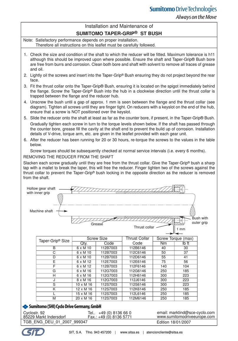
Sumitomo Drive Technologies TAPER-GRIP ST Instruction Manual

Sumitomo Drive Technologies
Sumitomo Drive Technologies HF-430NEO Series Operating instructions

Sumitomo Drive Technologies
Sumitomo Drive Technologies P1-PN Operating instructions

Sumitomo Drive Technologies
Sumitomo Drive Technologies PARAMAX SFC User manual

Sumitomo Drive Technologies
Sumitomo Drive Technologies VP2500L User manual

Sumitomo Drive Technologies
Sumitomo Drive Technologies Cyclo 6000 User manual

Sumitomo Drive Technologies
Sumitomo Drive Technologies P1-PB Operating instructions