INSTRUCTIONS
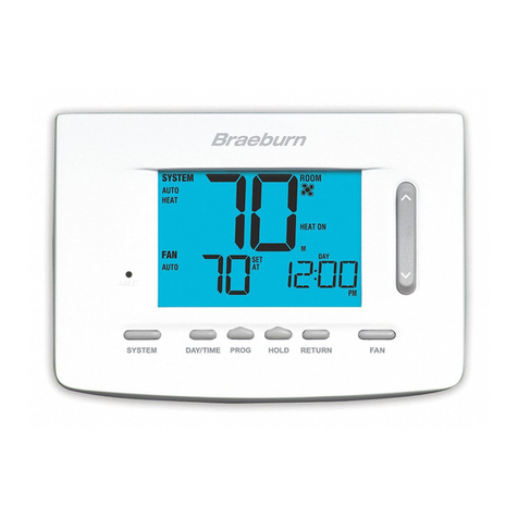
DAY/TIME
TheInstallerSettingsmustbeproperlyconguredinorderforthisthermostattooperatecorrectly.TheInstaller
Settingsaremenudriven.Theportionofthesesettingsthatdonotapplytoyoursetupwillbeskipped.These
settingsareindicatedbelowwithcomments.Moredetailoneachsettingfollowsthistable.
Installer Guide 10 11 Installer Guide
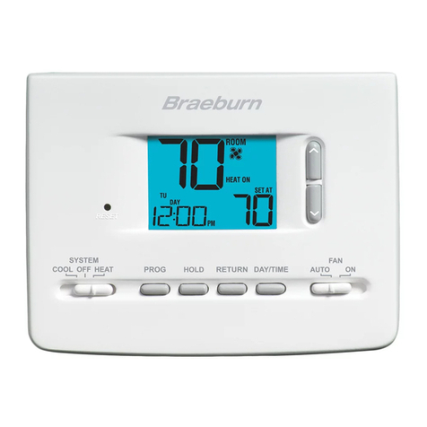
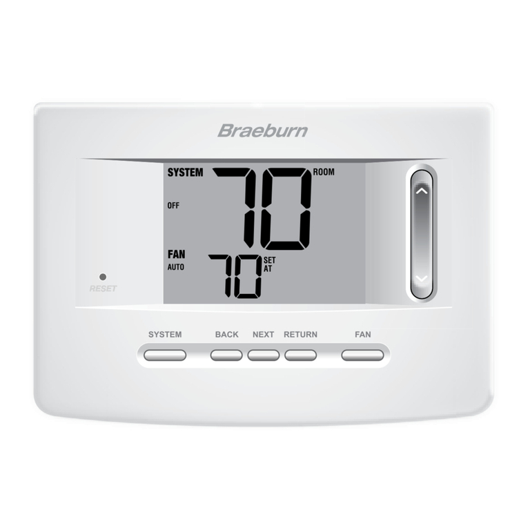
1. PressandholddowntheRETURNand
buttonsfor3seconds.
2. Releasebothbuttonsandtherstinstaller
settingwillbedisplayed.
3. Changesettingsasrequiredusingthe
orportionoftheSpeedBar®.
4. PressNEXT (HOLD)orBACK (PROG)to
movetothenextorprevioussetting,
pressRETURNtoexit.
No. Installer Setting Factory Setting Comments
(Notes follow this table) Default Options (More information follows this table)
1 Residentialor RES RES SelectforResidentialprole
orCommercialProle COMM SelectforCommercialprole
2 ProgrammingMode 7 PROG 7 PROG Selectfor7dayprogrammingmode
[note 1] 52 PROG Selectfor5-2dayprogrammingmode
NO PROG Selectfornon-programmablemode
3 ClockFormat 12 HR 12 HR Selectfor12hourclock
24 HR Selectfor24hourclock
4 TemperatureScale F DEG F DEG SelectforFahrenheitdisplay
C DEG SelectforCelsiusdisplay
5 AutoChangeover oF AUTO oF AUTO DisablesAutoChangeovermode
ON AUTO EnablesAutoChangeovermode
11CONV Selectfor1H/1CConventionalsystem
22CONV Selectfor2H/2CConventionalsystem
6 SystemType 11CONV 11HP Selectfor1H/1CHeatPumpsystem
22HP Selectfor2H/2CHeatPumpsystem
32HP Selectfor3H/2CHeatPumpsystem
1HD SelectforHeatOnlyHydronicsystem
11HD SelectforHydronicHeat/1Csystem
7 1stStageDifferential 0.5 DIF1 0.5, 1.0or Selecta1ststagetemperaturedifferentialof.5°,
2.0 DIF1 1°or2°F(.25°,.5°or2°C)
8 2ndStageDifferential 2.0 DIF2 1.0, 2.0, 3.0, Selecta2ndstagetemperaturedifferentialof1°,
[note 2] 4.0, 5.0or 2°,3°,4°,5°or6°F(.5°,1°,1.5°,2°,2.5°or3°C)
6.0 DIF2
9 3rdStageDifferential 2.0 DIF3 1.0, 2.0, 3.0, Selecta3rdstagetemperaturedifferentialof1°,2°,
[note 2] 4.0, 5.0or 3°,4°,5°or6°F(.5°,1°,1.5°,2°,2.5°or3°C)
6.0 DIF3
No. Installer Setting Factory Setting Comments
(Notes follow this table) Default Options (More information follows this table)
10 1stStageFanControl HG FAN 1 HG FAN 1 Selectfor1ststageGasheating
[note 3] HE FAN 1 Selectfor1ststageElectricheating
11 EmergencyHeat] HE EMER HE EMER SelectforElectricEmergencyHeat
FanControl[note 4] HG EMER SelectforGasEmergencyHeat
12 ReversingValve REVO REVO SelectforcoolactiveReversingValve(Oterminal)
(O/BTerminal)[note 5] REVB SelectforheatactiveReversingValve(Bterminal)
13 FossilFuel AE AUX AE AUX SelectforElectricAuxiliaryheat(withcompressor)
BackupHeat[note 4] AG AUX SelectforGasAuxiliaryheat(withoutcompressor)
14
CompressorPowerOutage
oF CPOP oF CPOP DisablesPowerOutageLockoutDelay
Protection [notes 4, 6] on CPOP EnablesPowerOutageLockoutDelay
15 ACPowerInterrupt
AC oF MONR
AC oF MONR DisablesACPowerInterruptWarning
Warning[note 6] AC on MONR EnablesACPowerInterruptWarning
16 CompressorShort 5 CSCP 5, 4, 3, 2or Selectacompressorshortcycleprotectiondelayof5,
CycleProtection[note 7] 0 CSCP 4,3,2or0minutes
17 ResidualCooling 60 FAN 90, 60, 30 SelectaResidualCoolingFanDelayof90,60,
FanDelay[note 7] or0 FAN 30or0seconds.
18 AdaptiveRecovery oF REC oF REC DisablesAdaptive(early)Recoverymode
Mode(ARM™) [note 8] on REC EnablesAdaptive(early)Recoverymode
19 IndoorRemoteSensor I SENS I SENS Temperatureissensedfromthermostatonly.
Control*[note 9] E SENS Temperatureissensedfromremotesensoronly.
A SENS Temperatureiscombinedwiththethermostatand
theremotesensor.
20 LockoutSecurityLevel 2 LOCK 2 LOCK Iflocked–Completelockoutisenabled
1 LOCK Iflocked–Partiallockoutisenabled(SpeedBar
®
is
stillfunctional)
21 AutoChangeover 3 BAND 2, 3, 4or5 SelectaDeadBandof2°,3°,4°or5˚F
DeadBand[note 10] BAND (1°,2°or3°C)forAutoChangeovermode.
22 CompressorBalance NO BALC NO BALC DisablesBalancePoints
Point[notes 4, 11] 15-50 BALC SelectaCompressorBalancePointof15°-50°F
(-9°-10°C)
23 AuxiliaryHeatBalance NO BALA NO BALA DisablesBalancePoints
Point[notes 4, 11]
70-40 BALA
SelectaAuxiliaryHeatBalancePointof70°-40°F
(21°-4°C)
24
HeatSetPointUpperLimit
90LIM 90-60 LIM
SelectaHeatSetPointUpperLimitof90°-60°F(32°-10°C)
25
CoolSetPointLowerLimit
45LIM 45-80 LIM
SelectaCoolSetPointLowerLimitof45°-80°F(7°-27°C)
[note 7]
*WhenaBraeburn
®
outdoorsensorisconnected,thethermostatautomaticallyrecognizesit.PressPROGandHOLDatthesame
timetodisplayoutdoortemperature.
NOTE: Additional options such as Service Monitors, setting the lock code, etc. are located in the User Settings –
See User manual for information on setting these options.
4
Installer Settings
NOTE: Shaded areas below do not apply to the 5020.


