manuals.online logo
Brands
  1. Home
  2. •
  3. Brands
  4. •
  5. Salus
  6. •
  7. Thermostat
  8. •
  9. Salus iT500 User manual

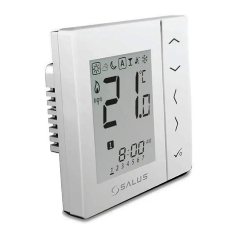
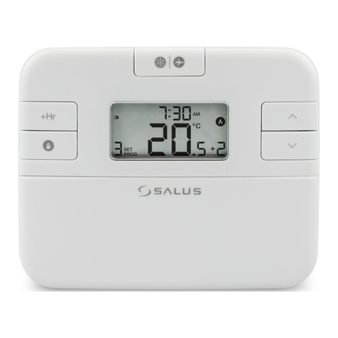
Salus iT500 User manual

Desk mount option iT500
iT500 Internet Thermostat
Importer:
SALUS Controls plc
Salus House, Dodworth Business Park
Whinby Road, Barnsley S75 3SP,
United Kingdom
DYSTRYBUTOR OF SALUS CONTROLS:
QL CONTROLS Sp. z o.o., Sp. k.
Rolna 4,
43-262 Kobielice,
Poland
www.salus-controls.eu
SALUS Controls is a member of the Computime Group
Maintaining a policy of continuous product development SALUS Controls plc reserve the right to
change specification, design and materials of products listed in this brochure without prior notice.
Introduction
Technical specication
iT500RX terminals description
Installation of iT500RX receiver
Inserting the batteries in the iT500 Thermostat
Connecting the gateway to your existing router
Button functions
LCD icon description
iT500 Plus application
Wiring diagrams for single heating zone
Wiring diagram for 2 heating zones
Product compliance
Safety information
This product complies with the following EU Directives: Electromagnetic Compatibility 2014/30/EU,
Low Voltage Directive 2014/35/EU, Directive 2014/53/EU and 2011/65/EU. Full information is available
on the website www.saluslegal.com
Use in accordance with national and EU regulations. Use the device only as intended, keeping it in a dry condition.
The product is for indoor use only. Installation must be carried out by a qualied person in accordance with national
and EU regulations.
Download the iT500 Plus app, create an account
and register your device. Follow the on screen
instructions to complete all the steps.
Features available only on the App:
• HOLIDAY mode
• Antifrost temperature changing
• Energy saving mode (set the lowest schedule temp.)
• Simplied schedule setup
- Conrm
- Return
- Settings / zone changing
- Increase
- Display ON (display highlighting)
- Decrease
The iT500 controls your heating and hot water from anywhere via your smartphone or laptop. Your pc and laptop
connects to the system using existing broadband connection. The system is wireless so it’s easy to instal.
FEATURES:
• Access and control your heating and hot water via the internet
• Compatible with your PC or smartphone - they connect to the system using your existing broadband connection
• Touch sensor panel
• The internal system uses 868 MHz for robust communication
• 3 system congurations:
- One central heating zone only
- Two central heating zones (optional iT300 remote sensor required for second zone)
- One central heating zone plus hot water
• ECO & HOLIDAY mode
• Free iT500 Plus app to download
Box contains:
- iT500TR thermostat
- iT500RX receiver (a wireless receiver that will connect to your boiler.
It is suitable for combination and system boiler).
- iTG500 Internet gateway - connects via a short cable to your broadband internet router.
The gateway enables internet access and control of your system.
Supply:
Rating Max:
Temperature range:
Frost protection temperature:
Hysteresis:
Storage temperature:
Protection degree IP:
iT500 - 2 x AA Batteries
iT300 - 2 x AAA Batteries
iT500RX - 230 V AC 50Hz
CH1: 16 A resistive, 5 A inductive
CH2: 5 A resistive, 3 A inductive
5°C - 35°C (in step 0,5°C)
5°C - 9°C (in step 0,5°C)
1°C
-20°C to 60°C
IP 30
Loosen the screws at the bottom
of the receiver unit and unclip the
front of the unit.
Remove the battery cover from
the base of the iT500 Thermostat.
+
Insert the second battery supplied
into the left hand side of the base
of the iT500 Thermostat.
Easy to use interface. With walk through tutorials
on how to use the App.
Simple to modify heating schedules.
Choose from ALL, 5/2
or INDIVIDUAL days.
Fit the back of the receiver unit to
the wall using the ttings supplied.
Thenwire up the receiver using
proper diagram.
Make a note of the serial number
printed inside the base of the
iT500 Thermostat.
Ensure the batteries are tted
securely in the base of the
iT500 Thermostat.
Clip the front of the unit back and
securely screw the front
of the receiver in place.
With the unit face down, insert
the rst battery supplied into
the right hand side of the base
of the iT500 Thermostat.
Replace the battery cover to
the base of the iT500 Thermostat.
1. Settings indicator
2. Internet indicator
3. RF signal indicator
4. Low battery status
5. Holiday indicator
6. Button lock indicator
7. Temperature unit
8. Temperature indicator
9. Hot water heating in continuous mode
10. Hot water override
11. Automatic mode
12. Antifrost mode
13. Hot water heating
14. Hot water indicator
15. Cooling mode indicator (zone 2)
16. Zone 2 indicator
17. Heat mode indicator (zone 2)
18. Cooling mode indicator (zone 1)
19. Zone 1 indicator
20. Heat mode indicator (zone 1)
21. Program number indicator
22. Clock display
23. Day of the week
1 2 3 4 5 6
1314
1518 1619 1720
7
23
22
21
8
9
10
11
12
1
1
4
2
2
5
3
3
6
Flashing red light on setup
Constant green
light when iT500
is connected to the
SALUS Controls Server.
3
You can make a note of your STA number here for future reference:
You can add a few iT500 thermostat to one account.
STA
Terminal
name Function
L,N 230V AC power supply
CH (zone 1) NC Normally closed terminal
NO Normally open terminal
COM Common Terminal
AUX (zone 2)
or
NC Normally closed terminal
NO Normally open terminal
COM Common Terminal
iT500 Plus iT500RX receiver switch functions
2
5
1
4
3
6
1. AUTO - receiver operate in automatic mode
(
works according to thermostat or app
)
2. MANUAL - receiver operate according to the switch
located below
3. OFF - receiver is disabled
4. CH - in manual mode, zone 1 are turned ON
5. AUX - in manual mode, zone 2 are turned ON
6. CH/AUX - in manual mode, zone 1 and zone 2
(or HW) are turned ON
Fitting the wall bracket and mounting the iT300
Note: iT300 purchased separately. Can only be used if your system supports second central heating zone.
Note: Always shut o the AC mains supply before installing or working on any components.
Insert the 2x AAA batteries supplied
in the battery case under the cover
on the back of iT300 unit.
Attach the wall mounting bracket
to a suitable wall using the ttings
supplied.
Align the grooves on the back
of the iT300 unit and slide onto
the bracket.
12 3
Installation of wall bracket docking (optional)
For best results mount iT500 1.5m from ground level.
Attach the wall mounting bracket
to a suitable wall using the ttings
supplied and the built in level.
After rst ensuring that the
bracket is secure, clip the iT500
into place by aligning the recess
on the back of the unit to the
bracket and clipping into place.
Once clipped into place, ensure
the unit is securely seated on the
bracket.
12 3
For the desk mounted option, simply clip the clear stand supplied separately
into the back of the unit.
Installation Manual
iT500TX
iT500RX
L
N
COM
NC NO NC NO
COML
N
AC
230 V
Mor
iT500TX
iT500RX
L
N
COM
NC NO NC NO
COML
N
AC
230 V
iT500TX
iT300
iT300
iT500RX
L
N
COM
16(5)A 5(3)A
16(5)A 5(3)A
16(5)A
230 V AC
230 V AC
230 V AC
5(3)A
NC NO NC NO
COML
N
AC
230 V
Mor
M
or
iT500TX
iT500RX
L
N
COM
16(5)A 5(3)A
NC NO NC NO
COML
N
AC
230 V
iT500TX
iT500RX
L
N
COM
NC NO NC NO
COML
N
AC
230 V
Mor
iT500TX
iT500RX
L
N
COM
NC NO NC NO
COML
N
AC
230 V
iT500TX
iT300
iT300
iT500RX
L
N
COM
16(5)A 5(3)A
16(5)A 5(3)A
16(5)A
230 V AC
230 V AC
230 V AC
5(3)A
NC NO NC NO
COML
N
AC
230 V
Mor
M
or
iT500TX
iT500RX
L
N
COM
16(5)A 5(3)A
NC NO NC NO
COML
N
AC
230 V
- antifrost mode 5°C
(changing temperature is avaible
only through the app)
- automatic mode
(works according to the schedule)
Press or button
to set start hour for program 1.
Press button to conrm.
Press or button
to set start hour for program 1.
Press button to conrm.
Press or button
to set start minutes for program 1.
Press button to conrm.
Press or button
to set start minutes for program 1.
Press button to conrm.
You can cancel temporary override by holding button
for 3 seconds. Setting indicator should disappear.
Press or button
to change temperature.
Press button to conrm.
Set hour value of boosting your
hot water by pressing
or button.
Press button to conrm.
Press button to select
temperature zone or HW.*
Press button to select
temperature zone or HW.*
Press button to select
temperature zone.*
Press button to select
hot water system .
*(only in two heating zones or one heating
zone + hot water system)
*(only in two heating zones or one heating
zone + hot water system)
*(only in two heating zones)
When iT500RX receiver
and iT500 thermostat are paired
then the light will be green.
Press or to return
to the home screen.
iT500 has successfully paired with
iT300 when the antenna stops
ashing.
Press or to return
to the home screen.
Press and hold and
buttons for 3 sec.
Press and hold and
buttons for 3 sec.
Press and hold and
buttons for 3 sec.
GMT GMT+1 Hour GMT+2 Hour GMT+3 Hour
or or or
Press or button
to select temperature unit.
Press button to conrm.
Press or button
to select operating mode.
Press button to conrm.
Press or button
to select time zone (GMT).
Press button to conrm.
Press or button to select heating or cooling* mode. Press button to conrm.
*Cooling can only be selected if your system supports this.
5a 5b
6 7
5c
UK
IRELAND
PORTUGAL
ICELAND*
RUSSIA*AUSTRIA
POLAND
GERMANY
CZECH
SPAIN
FRANCE
ITALY
SWITZERLAND
LUXEMBOURG
HOLLAND
BELGIUM
DENMARK
SWEDEN
NORWAY
MALTA
CROATIA
SERBIA
BOSNIA
SLOVENIA
SLOVAKIA
ESTONIA
TURKEY
CYPRUS
GREECE
ROMANIA
RUSSIA
UKRAINE
BULGARIA
LITHUANIA
BELARUS*
FINLAND
MOLDOVA
LATVIA
The countries marked with * do not observe Daylight SavingTime. For details please see below.
8
DST (Daylight Saving Time) ON will automatically change your time
from summer to winter.
Press or button
to turn ON or OFF day saving
time function.
Press button to conrm.
Pairing iT500 with iT500RX receiver
Program schedule for heating zone
Program schedule for hot water system
Setting the temperature
Operating modes
Setting the time and date
Pairing the iT300 to the thermostat
Lock Function
Using a paper clip, insert into the
hole marked SYNC at the bottom
of iT500RX receiver.
To pair iT300 to the receiver, insert
a paperclip or similar object into
the hole on the left hand side
of iT300 for 2 seconds.
Press button to launch
pairing process.
Press button to launch
pairing process.
Press or button
to set temperature level for
program 1. Press button
to conrm.
Follow the steps 7-9
to set next programs.
Set time for turn OFF program 1
cognately to step 7-8.
Press button to conrm.
Follow the steps 7-9 to set
next programs.
The bottom switch will show
a constant red light when iT500RX
receiver is ready to pair.
Now go to iT500 thermostat.
A red light will ash in the top
right hand corner of the iT300.
Pairing process can take
up to 10 minutes.
Pairing process can take
up to 10 minutes.
1
1
5
5
2
2
6
6
3
1
3
4
2
4
7
7
FAILSAFE MODE: In the event of RF signal loss, your system will
be switched on for 4 minutes, then o for 11 minutes. If you want to
disable FAILSAFE MODE when RF link has been lost then move the
slide switch on iT500RX to either the Manual or O position.
The iT300 should be installed
in the area of the house that
the second zone will be
controlled from, ie. Upstairs.
Please note the red LED
on the iT300 will continue to
ash and eventually timeout.
You can easily set your schedule via iT500 Plus app . If you want to set schedules directly by the iT500
thermostat, please follow the instruction below.
When connected to the internet, the iT500 will set time and date automatically. However this can also be set
manually.
1
4
2
5
3
6
Press and hold button. Press again button
to change value.
Press button to conrm.
Press or button
to set 12 or 24 hour format.
Press button to conrm.
Press or button
to set the hour.
Press button to conrm.
Follow the same steps to set
the minutes, day, month
and year.
Permanent manual mode
To enable or disable lock function press and hold and buttons
together.
Press the power button
to highlight the display.
Press the power button
to highlight the display.
Press the power button
to highlight the display.
12
3a
3b
Press the power button
to highlight the display.
Press and hold button
for 3 seconds.
Press and hold button
for 3 seconds.
Press button to conrm.
1
1
4
4
7
7
2
3
2
5
5
8
8
3
4
3
6
6
9
9
Press the power button
to highlight the display.
Press the power button
to highlight the display.
Note: In program schedule for hot water system (HW)
you can set 3 schedule programs per day.
For each HW program you must dene the time of start and the time of the end.
Note: When you set program schedule, necessarily set all 6 programs. I.e. if you want to set 2
temperature levels, you need to set rst temperature level for 1 to 5 program and set second
temperature level only for program 6.
In iT500 thermostat you can dene 6 schedule programs per day. You can set dierent temperature level for each
program. While programming specic time interval you must be aware that you are about to set at what time the
program will start. For example, if you set program 1 for 6:00 (AM) it means the program is going to run at 6:00 (AM)
and will running till the time set for next program. Example of 4 temperature levels for 6 schedule programs:
P1
17°C 17°C
22°C 23°C 23°C 23°C
19°C
P2 P3 P4 P5 P6
P1
0 1 2 3 4 5 6 7 8 9 10 11 12 13 14 15 16 17 18 19 20 21 22 23 24
Press button to choose
ALL, 5/2 or INDIVIDUAL days.
Press button to conrm.
Press button to choose
ALL, 5/2 or INDIVIDUAL days.
Press button to conrm.
Setting up the iT500 thermostat
After powering up iT500 for the rst time the display will go through the following sequence.
OTA (Over The Air
operated software)
revision number
The globe icon will
appear when the unit
automatically connects to
the internet via the SALUS
iTG500 Gateway. This
should take approximately
20 seconds.
iT500 Software revision
132 4
Selecting your system conguration
At any time press for return to the previous step or hold for 5 seconds to return to the home screen.
Press and hold
and buttons for 3 sec.
Press button to conrm.
Two central heating zones.One central heating zone.
++
One central heating zone
+ hot water system
Press or button to select your system conguration. To conrm press button.
This menu should only be entered by the installer as changes can have a detrimental eect on your heating system.
12
4b
4a
3
4c
Press the power button
to highlight the display.
Note: If you set the temperature in AUTO mode (temporary override) the setpoint temperature won’t be
changed until the next program starts.
Note: iT300 purchased separately. Can only be used if your system supports second central heating zone.

Other manuals for iT500

8

This manual suits for next models

2

Other Salus Thermostat manuals

Salus RT510RF User manual

Salus

Salus RT510RF User manual

Salus QUANTUM SQ610RF User manual

Salus

Salus QUANTUM SQ610RF User manual

Salus Quantum SQ610 User manual

Salus

Salus Quantum SQ610 User manual

Salus Optima S User manual

Salus

Salus Optima S User manual

Salus WBRT520TX User manual

Salus

Salus WBRT520TX User manual

Salus ERT50 User manual

Salus

Salus ERT50 User manual

Salus ERT30 User manual

Salus

Salus ERT30 User manual

Salus ST880ZB User manual

Salus

Salus ST880ZB User manual

Salus RT310SR User manual

Salus

Salus RT310SR User manual

Salus HTR-RF(20) User manual

Salus

Salus HTR-RF(20) User manual

Salus ST620WBC User manual

Salus

Salus ST620WBC User manual

Salus Quantum WQ610 User manual

Salus

Salus Quantum WQ610 User manual

Salus iT500 User manual

Salus

Salus iT500 User manual

Salus FC600 User manual

Salus

Salus FC600 User manual

Salus AS20WRF User manual

Salus

Salus AS20WRF User manual

Salus VS30W User manual

Salus

Salus VS30W User manual

Salus RT510BC User manual

Salus

Salus RT510BC User manual

Salus Thermo 091 User manual

Salus

Salus Thermo 091 User manual

Salus HTRP24 User manual

Salus

Salus HTRP24 User manual

Salus ZigBee User manual

Salus

Salus ZigBee User manual

Salus RT310i User manual

Salus

Salus RT310i User manual

Salus ST325TX User manual

Salus

Salus ST325TX User manual

Salus VS05 User manual

Salus

Salus VS05 User manual

Salus 091FL User manual

Salus

Salus 091FL User manual

Popular Thermostat manuals by other brands

Jackson Systems WCT-32 installation manual

Jackson Systems

Jackson Systems WCT-32 installation manual

HVAC Controls RTC70.XX Instructions for use

HVAC Controls

HVAC Controls RTC70.XX Instructions for use

Siemens RDS120 quick guide

Siemens

Siemens RDS120 quick guide

Honeywell T6811 Series Specification data

Honeywell

Honeywell T6811 Series Specification data

KMC Controls CTE-5201 Installation and operation guide

KMC Controls

KMC Controls CTE-5201 Installation and operation guide

Honeywell TRADELINE T8090A owner's manual

Honeywell

Honeywell TRADELINE T8090A owner's manual

Flexel TH132-AF manual

Flexel

Flexel TH132-AF manual

Johnson Controls TEC2004-4 installation instructions

Johnson Controls

Johnson Controls TEC2004-4 installation instructions

Hans Grohe RainSelect 1531318X Instructions for use/assembly instructions

Hans Grohe

Hans Grohe RainSelect 1531318X Instructions for use/assembly instructions

Honeywell T8621A user manual

Honeywell

Honeywell T8621A user manual

Danfoss Icon Master user guide

Danfoss

Danfoss Icon Master user guide

finder BLISS T 1T.91 manual

finder

finder BLISS T 1T.91 manual

SUNSTONE SS-PSTAT Easy Programming Guide

SUNSTONE

SUNSTONE SS-PSTAT Easy Programming Guide

Eaton CHVZ-01/05 Instruction leaflet

Eaton

Eaton CHVZ-01/05 Instruction leaflet

Honeywell LP916A installation instructions

Honeywell

Honeywell LP916A installation instructions

RDZ BC-RF Technical manual

RDZ

RDZ BC-RF Technical manual

Roth Minishunt Plus Installation

Roth

Roth Minishunt Plus Installation

Honeywell RTH2300 series owner's manual

Honeywell

Honeywell RTH2300 series owner's manual

manuals.online logo
manuals.online logoBrands
  • About & Mission
  • Contact us
  • Privacy Policy
  • Terms and Conditions

Copyright 2025 Manuals.Online. All Rights Reserved.