manuals.online logo
Brands
  1. Home
  2. •
  3. Brands
  4. •
  5. BRAHMA
  6. •
  7. Control Unit
  8. •
  9. BRAHMA SR3 User manual

BRAHMA SR3 User manual

SR3 - VE3 - BV3 - GV2
CONTROL BOXES
CONTROL BOXES FOR FORCED
DRAUGHT GAS BURNERS, WITH
POWER UP TO 120KW.
DESCRIPTION
The SR3 - VE3 - BV3 - GV2 safety devices aresuitable to
control forced draught gas burners for civil and industrial
applications.
The BV3 control is used for fast boilers in which hot water
(or steam) taking has to occur within short times,which
cannot be granted by using the SR3 and VE3 devices.
The GV2 control boxis used for small boilersin which a
longersafety time is generally allowed.
According to TÜV Bayern, Monaco, the SR3 control is in
compliance with the German regulation DIN 4788, part 3,
for power up to 120KW.It also obtained the DIN-DVGW
89.11fBN approval, nowexpired and notrenewable.
The “Laboratorio di Macchine eTermotecnica del Centro
Studi ed Esperienze” in Rome, Capannelle, tested the SR3
control for power up to 93KW,which obtained the
certification no. 3704/81/77/3A and the approval of the
Ministry of the Interior for fire prevention (circularsno. 68
and no. 42).
TECHNICAL DATA:
Supplyvoltage: 220V(-15% +10%)
50Hz (±5%)
on request: 110V
Operating temperature range: -10°C +60°C
Protection degree: IP40
Starting power consumption: 10VA
Operating power consumption: 6,5VA
Max. current rating Imax.
-burnermotor: 4 A
- EV valve: 2 A
- ignition transformer: 2 A
- alarm: 1 A
Regulators (T, PA, PG): 6 A
Times:
- prepurge time (TV):
SR3 - VE3: 50 s
BV3 - GV2: 20 s
-safety time (TS): GV2: 15 s
SR3 - VE3 - BV3: 3 s
-dropout time on running
flame failure: <1 s
Flame control:
- minimum ionization current: 0,5µA
- recommended ionization current: 7µA
- minimum insulation resistance between
probe, cable and ground: > 50MΩ
- voltage on the detection probe: 300V
Weight including socket: 550 g
FLAME CONTROL
Atransformer having one primary and twosecondary
windings supplies the electronic flame detection circuit at
lowvoltage, and the detection probe with about 300V. This
supply system offers the big advantage ofhaving constant
ionization values, even if the network is a live-live
installation.
To check the efficiency of the flame detection circuit, you
have to proceed as follows: connectalowimpedance
ammeter,as shownin Fig.1; the R1 ...Rn resistorsin
series must give the total resistance value of 200MΩ(e.g.
20 resistors of 10MΩ1/4W5%). Ifthe control boxis
supplied with 220V, the measured current value is about
0,5+0,6µADC, which causes the flame relay to switch on.
Lower current values indicate that the circuitis damaged or
only partially efficient.
4009_r00
1/4
Fig.1
CONSTRUCTION
The components ofthe control boxare fixed on apressed
frame made of thermohardening material, with high
dielectric resistance. The plastic casing protects the device
from possible damages resulting from crashes, incautious
opening, dust and contact with the external environment.
Flexible unipolar conductors of different sizes connect the
components of the control,except for the flame detection
and prepurge control circuit,which is mounted on aprinted
circuit.
OVERALL DIMENSIONS
The overall dimensions of the control boxare shownin
Fig.2.
Fig.2
ACCESSORIES
The control is provided with inbuilt reset button and
luminous lockout signal.
It can be supplied with kanthal flame detection probes in
different executions (see, for instance,Fig.3).
The casing is arranged for the fitting of corehitches and/or
cable holders on itssides;also these accessories can be
supplied on request.
Fig.3
CONNECTION
As regards the interconnection system of this control,
several solutions arepossible and different types of
connecting sockets can be employed (see Fig.4 and Fig.5).
Socket Ndiffersfrom sockets Aand Bfor itsdimensions
and the greater number of terminals connecting neutral and
ground.
Sockets A - B
Fig.4
Socket N
Fig.5
DIRECTIONS FOR INSTALLATION
− Control boxes are safety devices and must not be
opened; the manufacturer’s responsibility and
guarantee are invalidated if the control is opened.
− For safety reasons aregulation shutdownmust occur
every 24 hours.
− The control can be mounted in any position.
(*) The dimensions differ accordingto
the type of socket: 5with socket A
9 with socket B
h: Dimensionsdepending on the type
of socket: 95 with socket A
99 with socket B
98.3 with socket N
2/4 4009_r00
− Live and neutral must be connected correctly; a
mistake could cause a dangerous situation.
− The earth terminal of the control, the metal frame of the
burner, the earth of the ignition transformerand the
earth of the main supply must be well connected.
− Make sure that the discharge of the ignition transformer
does not hit the detection probe.
− The connecting wire of the detection probe must notbe
longerthan 20 m.
− Avoid putting the detection cable close to power or
ignition cables.
− Use aheat resistant cable and detection probe, well
insulated to the ground and protected from humidity or
water in general.
− Always check the control before the first startand also
after any replacement or after along period of non-
operation of the system. In particular make sure that:
− The connections arecorresponding to the scheme
below.
− The intervention of limiters and safety devices causes a
safety shutdown according to the application.
− The level of the flame signal is high enough.
− Ashort circuit between detection probe and burner
casing does not cause any flame simulation.
− In running state,aleakage of the detection probe tothe
ground causes the interruption of the oil flowand the
starting of anewignition cycle in the case of the BV3
and VE3 controls, while it causes alockout in the case
of the SR3 and GV2 controls.
THERMAL TIMERS
The safety time is given by acompensated thermal timer.
The fixed value of 220 V/20°Cdoes notvary of morethan
25% with voltage (-15% +10%) and temperature(-10
+60°C) variations.
The prepurge time is obtained by means of acompensated
thermal timer too; in the controls type SR3and VE3it is
possible to obtain very exact prepurge times even after
frequent and repeated starts of the unit,by exploiting the
bimetal both in the heating and in the cooling stage.
OPERATING CYCLE
When thermostats and gas pressure switch are closed, the
control boxstarts up the burner motor.During this period
the device carries out aself-check; if the check is positive
the cycle continues, and at the end of the prepurge stage
the valve and the ignition transformerare simultaneously
supplied.
During the safety time the flame has to become steady,
otherwise the control effects alockout.Consequently, the
valve and the ignition transformer aredeenergized, while
the lockout signal is supplied.
If a limiterorregulatoris opened, the oil flowis immediately
stopped and the burneris switched off.
The enclosed cycle diagrams are useful for abetter
understanding of the operating cycle of each control box.
Abnormal operation:
- Air flowfailure
SR3 - VE3: in case of failure of the air pressureswitch
the control proceeds to lockout at the end of the
prepurge time.
BV3: in case of failure of the airpressureswitch the
control continues the prepurge stage.
- Parasitic flame
The presence of aparasitic flame signal at start or
during the prepurge time causes alockoutimmediately
or at the end ofthe prepurge time.
Flame failure during operation causes different behaviour,
according to the type of control:
SR3 - GV2: reignition attempt with transformersupply
for amax.period corresponding to the safety time; after
this delay, in case no sparkrestoration occurs, the
control performs a lockout.
VE3 - BV3: repetition of the whole ignition cycle.
RESET OF THE CONTROL
To reset the control after alockout,act on the button after
waiting for the restoration ofthe lockout thermal, which
usually takes about 20 seconds.
ELECTRIC SCHEME SYMBOLS
BF: postpurge and lockout thermal BRF: flame detection relay
BRM: operation relay BRR: repetition cycle relay
ER: detection probe EV: gas valve
M: burner casing MB: burner motor
PA: air pressure switch PG: gas pressure switch
SB: lockout signal TA: ambient thermostat
TC: boiler thermostat TP: thermalprogrammer
TR: ignition transformer
ELECTRIC SCHEME SR3
LIVE
NEUTRAL
FLAME
DETECTION
CIRCUIT
ELECTRIC SCHEME GV2
LIVE
FLAME
DETECTION
CIRCUIT
NEUTRAL
ELECTRIC SCHEME VE3
LIVE
FLAME
DETECTION
CIRCUIT
NEUTRAL
4009_r00
3/4
ELECTRICSCHEME BV3
LIVE
NEUTRAL
FLAME
DETECTION
CIRCUIT
ELECTRIC SCHEME SYMBOLS
BF: postpurge and lockout thermal BRF: flame detection relay
BRM: operation relay ER: detection probe
EV: gas valve M: burner casing
MB: burner motor PA: air pressure switch
PG: gas pressure switch SB: lockout signal
TA: ambient thermostat TC: boiler thermostat
TP: thermalprogrammer TR: ignition transformer
BRAHMAS.p.A.
Via delPontiere, 31
37045 Legnago (VR)
Tel. +390442 635211 - Telefax+39 0442 25683 03/03/26 Subject to amendments without notice
http://www.brahma.it
E
-
mail: brahma@brahma.it
4/4 4009_r00

This manual suits for next models

3

Other BRAHMA Control Unit manuals

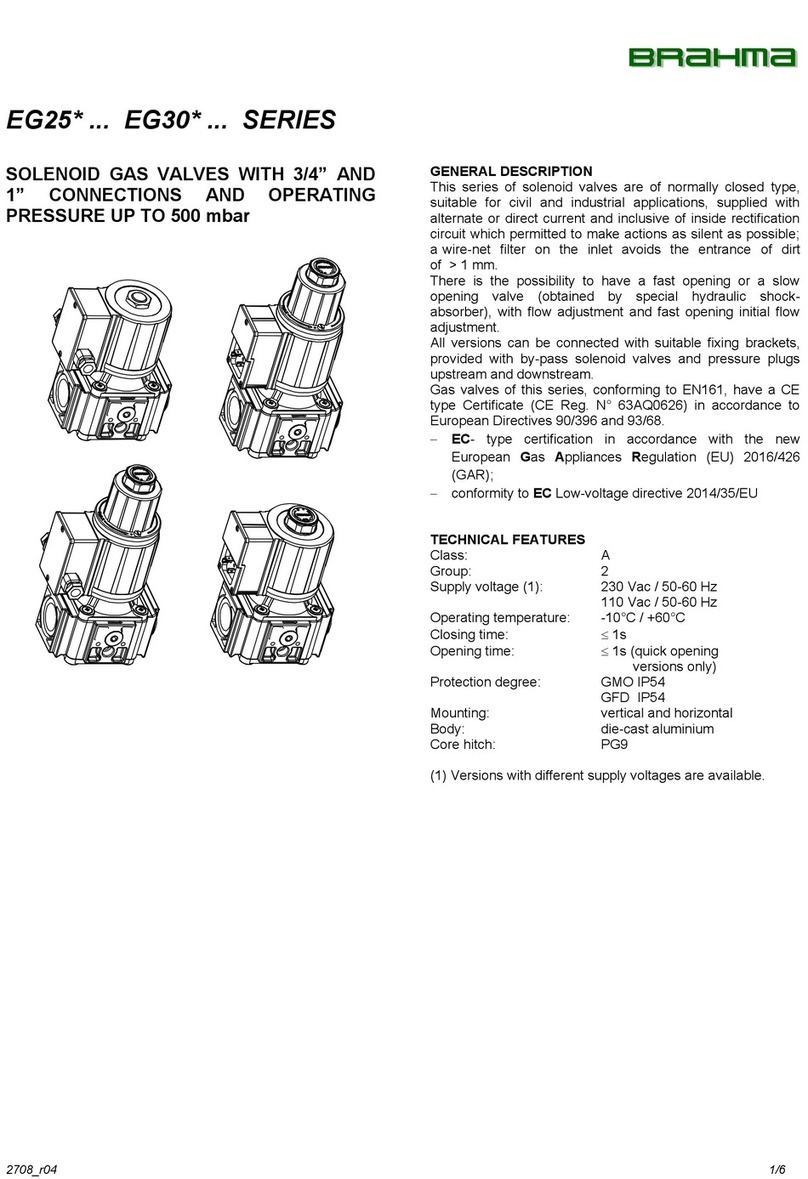
BRAHMA EG25 Series User manual

BRAHMA

BRAHMA EG25 Series User manual

BRAHMA E8 Series User manual

BRAHMA

BRAHMA E8 Series User manual

BRAHMA EG12 Series User manual

BRAHMA

BRAHMA EG12 Series User manual

BRAHMA EVN25 Series User manual

BRAHMA

BRAHMA EVN25 Series User manual

BRAHMA DV Series User manual

BRAHMA

BRAHMA DV Series User manual

Popular Control Unit manuals by other brands

Blain Hydraulics L10 manual

Blain Hydraulics

Blain Hydraulics L10 manual

Automationdirect.com Productivity P1-04DAL-1 manual

Automationdirect.com

Automationdirect.com Productivity P1-04DAL-1 manual

Pulsar MPSB48 quick start guide

Pulsar

Pulsar MPSB48 quick start guide

ETAS ES420.1 user guide

ETAS

ETAS ES420.1 user guide

Balluff BNI IOL-302-S02-Z012-C11 user guide

Balluff

Balluff BNI IOL-302-S02-Z012-C11 user guide

King gates Star D1230 instruction manual

King gates

King gates Star D1230 instruction manual

Silicon Laboratories EMBER EM358 series Reference manual

Silicon Laboratories

Silicon Laboratories EMBER EM358 series Reference manual

XIAMEN OCULAR GDM12864A user guide

XIAMEN OCULAR

XIAMEN OCULAR GDM12864A user guide

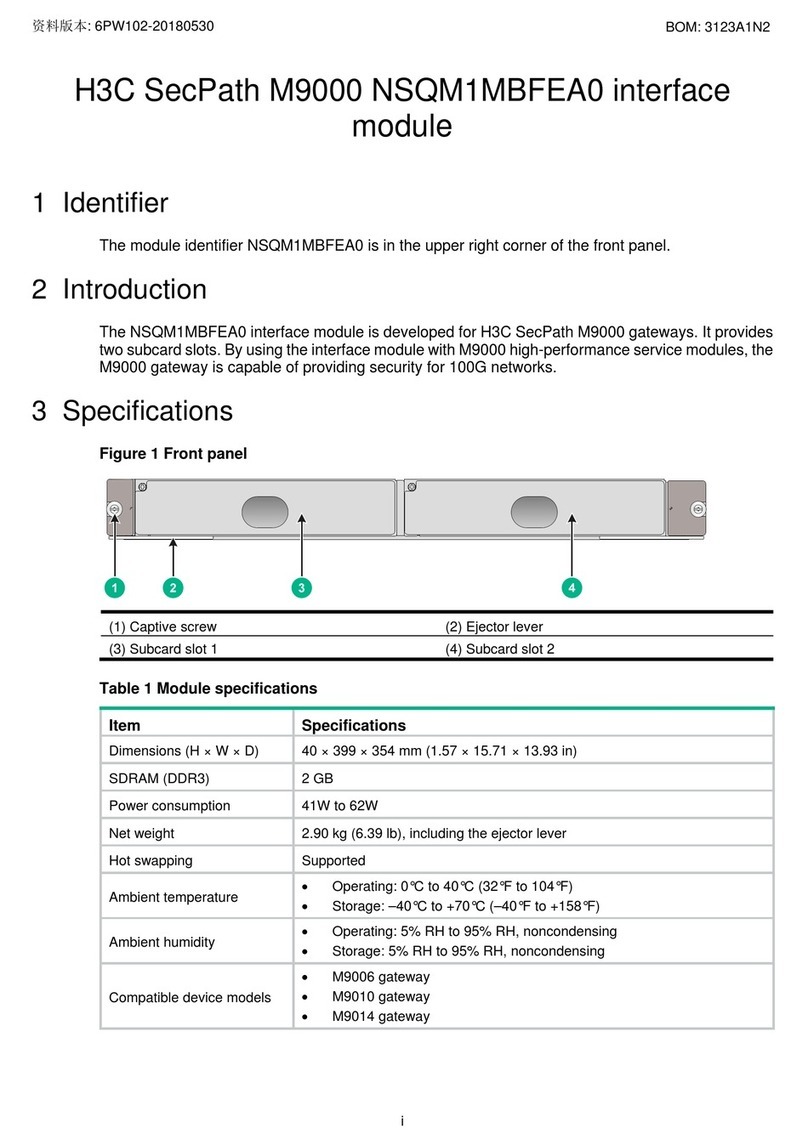
H3C SecPath M9000 NSQM1MBFEA0 quick start guide

H3C

H3C SecPath M9000 NSQM1MBFEA0 quick start guide

Hayward OmniPL HLPRO4NSW installation manual

Hayward

Hayward OmniPL HLPRO4NSW installation manual

ABB ACS850 series Application guide

ABB

ABB ACS850 series Application guide

Emerson EXD-U02 operating instructions

Emerson

Emerson EXD-U02 operating instructions

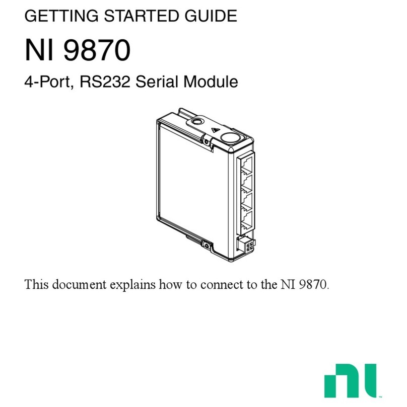
National Instruments NI 9870 Getting started guide

National Instruments

National Instruments NI 9870 Getting started guide

National Instruments FlexRIO PXIe-79 R Series installation guide

National Instruments

National Instruments FlexRIO PXIe-79 R Series installation guide

Grant GEO360 Installation & user's instructions

Grant

Grant GEO360 Installation & user's instructions

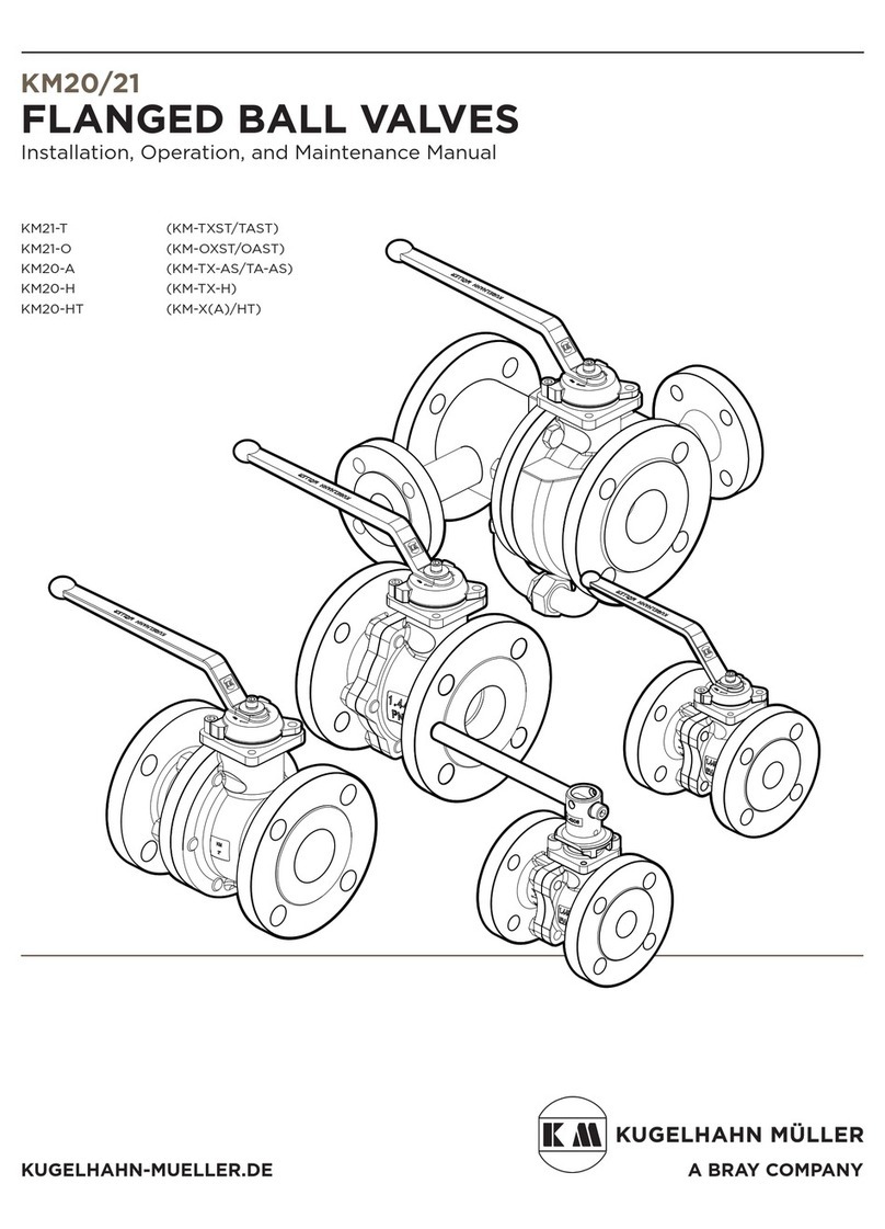
Bray KUGELHAHN MULLER KM20 Installation, operation and maintenance manual

Bray

Bray KUGELHAHN MULLER KM20 Installation, operation and maintenance manual

Sleipner ECU user manual

Sleipner

Sleipner ECU user manual

Nice MNCUT Instructions and warnings for installation and use

Nice

Nice MNCUT Instructions and warnings for installation and use

manuals.online logo
manuals.online logoBrands
  • About & Mission
  • Contact us
  • Privacy Policy
  • Terms and Conditions

Copyright 2025 Manuals.Online. All Rights Reserved.