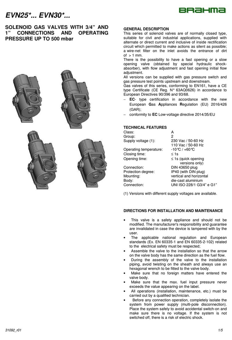
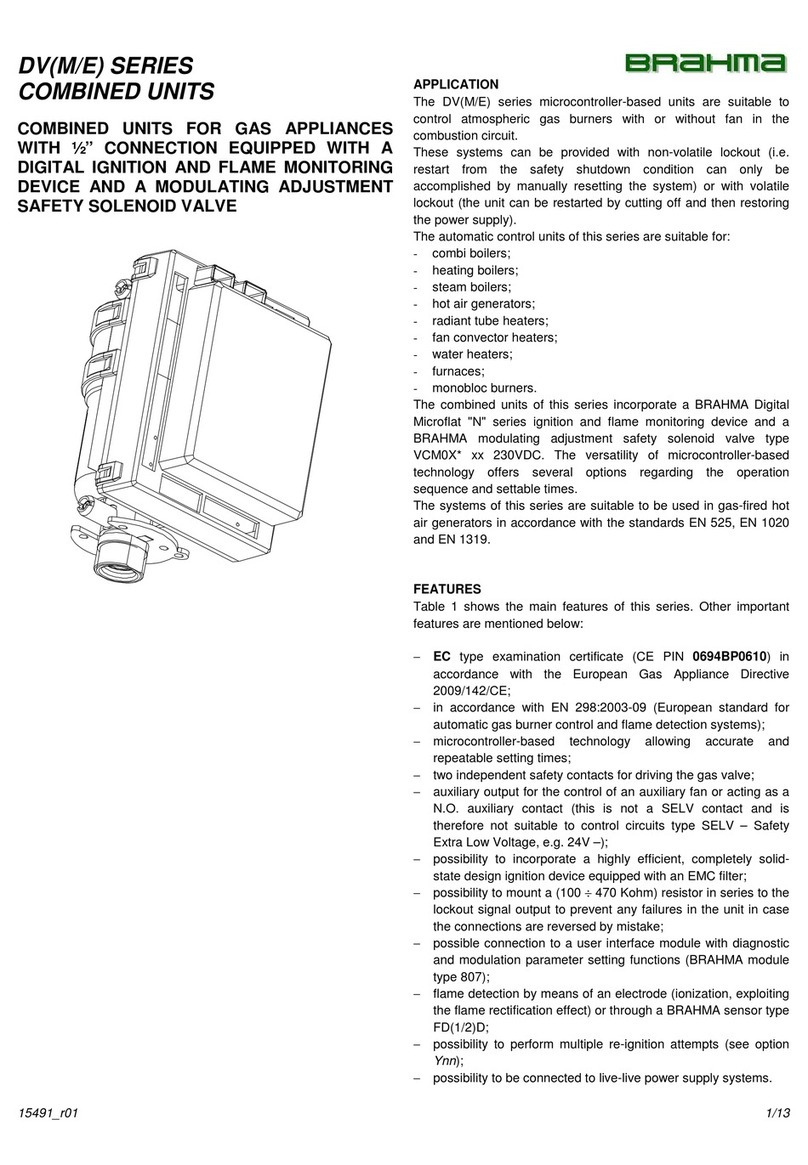
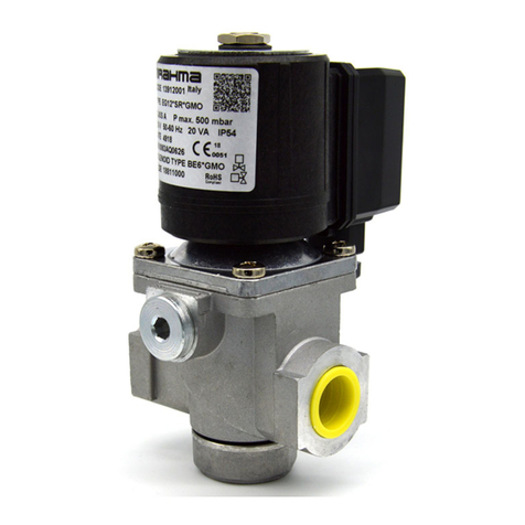
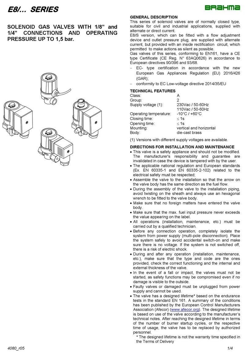
BRAHMA EG25 Series User manual

2708_r04 1/6
EG25* ... EG30* ... SERIES
SOLENOID GAS VALVES WITH 3/4” AND
1” CONNECTIONS AND OPERATING
PRESSURE UP TO 500 mbar
GENERAL DESCRIPTION
This series of solenoid valves are of normally closed type,
suitable for civil and industrial applications, supplied with
alternate or direct current and inclusive of inside rectification
circuit which permitted to make actions as silent as possible;
a wire-net filter on the inlet avoids the entrance of dirt
of > 1 mm.
There is the possibility to have a fast opening or a slow
opening valve (obtained by special hydraulic shock-
absorber), with flow adjustment and fast opening initial flow
adjustment.
All versions can be connected with suitable fixing brackets,
provided with by-pass solenoid valves and pressure plugs
upstream and downstream.
Gas valves of this series, conforming to EN161, have a CE
type Certificate (CE Reg. N° 63AQ0626) in accordance to
European Directives 90/396 and 93/68.
−EC- type certification in accordance with the new
European Gas Appliances Regulation (EU) 2016/426
(GAR);
−conformity to EC Low-voltage directive 2014/35/EU
TECHNICAL FEATURES
Class: A
Group: 2
Supply voltage (1): 230 Vac / 50-60 Hz
110 Vac / 50-60 Hz
Operating temperature: -10°C / +60°C
Closing time: 1s
Opening time: 1s (quick opening
versions only)
Protection degree: GMO IP54
GFD IP54
Mounting: vertical and horizontal
Body: die-cast aluminium
Core hitch: PG9
(1) Versions with different supply voltages are available.

2/6 2708_r04
DIRECTIONS FOR INSTALLATION AND MAINTENANCE
•This valve is a safety appliance and should not be
modified. The manufacturer's responsibility and guarantee
are invalidated in case the device is tampered with by the
user.
•The applicable national regulation and European
standards (Ex. EN 60335-1 and EN 60335-2-102) related
to the electrical safety must be respected;
•Assemble the valve to the installation so that the arrow
on the valve body has the same direction as the fuel flow.
•During the assembly of the valve to the installation
piping, avoid twisting on the sheath and always use an
hexagonal wrench to be fitted to the valve body.
•Make sure that no foreign matters have entered the
valve body.
•Make sure that the max. fuel input pressure never
exceeds the value appearing on the label.
•All operations (installation, maintenance, etc.) must be
carried out by a qualified technician.
•Before any connection operation, completely isolate the
system from power supply (multi-pole disconnection).
Place the system safely to avoid accidental switch-on and
make sure there is no voltage. If the system is not
switched off, there is a risk of electric shock.
•During and after any operation (installation,
maintenance, etc.), make sure that the type and code are
the ones provided, check the correct functioning and the
internal and external thickness of the valve.
•In the event of a fall or impact, the valves must not be
started, as safety functions may be compromised even if
no damage is visible to the outside.
•Faulty valves or damaged must be unplugged from power
supply and cannot be used.
•The valve has a designed lifetime* based on the
endurance tests in the standard EN 161. A summary of
the conditions has been published by the European
Control Manufacturers Association (Afecor)
(www.afecor.org). The designed lifetime is based on use
of the valve according to the manufacturer’s technical
notes. After reaching the designed lifetime in terms of the
number of burner startup cycles, or the respective time of
usage, the valve has to be replaced by authorized
personnel.
* The designed lifetime is not the warranty time specified
in the Terms of Delivery.
SOLENOID VALVES CONNECTIONS
It is possible to connect two valves with two fixing brackets
and an O-ring to guarantee the sealing. The whole system is
blocked by two screws, as shown in Fig. 1. This method
permits to avoid the onerous use of threaded junctions.
Fig. 1

2708_r04 3/6
DIRECTIONS FOR EG25*L... AND EG30*L... VALVES
ADJUSTMENT
Flow adjustment
To adjust the gas flow, you have to remove one of the two
screws used to fasten the lag group (the not enamelled one,
marked with 4 in Fig. 2) and rotate clockwise the whole group
to reduce the flow or in the opposite direction to increase it.
Opening time adjustment
After removing the top protection, by rotating it
counterclockwise, you have to act on the adjustment screw,
marked with 1 in Fig. 2; by rotating clockwise, the opening
time becomes longer, by rotating in the opposite direction, the
opening time becomes shorter.
Quick release initial flow adjustment
After removing the top protection by rotating it
counterclockwise, if you rotate clockwise the nut marked with
2 in Fig. 2, the initial release will be reduced; if you rotate the
same nut counterclockwise, the initial release will be
increased.
1
2
3
4
Fig. 2
DIRECTIONS FOR EG25*SR... AND EG30*SR... VALVES
ADJUSTMENT
Flow adjustment
After removing the top protection by rotating it
counterclockwise, rotate clockwise the screw marked with 1
in Fig. 3 to reduce the flow, rotate in the opposite direction to
increase the same.
1
Fig. 3
SOLENOID VALVES WITH BY-PASS
All versions of EG25*... and EG30*... valves can be equipped
with a by-pass valve (with orifice diameter 11 mm) directly
fitted on the body. In this way it is avoided the installation of a
separated by-pass valve.
Both to the main valve and to the by-pass one, flow is given
from the same inlet gas pipe, even if they have different
electrical controls.
By-pass valve can have fast or slow opening, and can be with
or without flow adjuster, but anyway inclusive of an inside
rectification circuit, which permitted to use suitable
attenuators, to make its actions as silent as possible.
EG25 BY-PASS
EG30 BY-PASS

4/6 2708_r04
OVERALL DIMENSIONS
EG25*S.3*GMO
EG25*SR.3*GMO
EG25*L.3*GMO
EG25*L.1*GMO
EG25*SR.1*GMO
EG25*S.1*GMO
EG25*.1*GFD
See note
below
EG25*.3*GFD
See note
below
EG30*S.5*GMO
EG30*SR.5*GMO
EG30*L.5*GMO
EG30*L.2*GMO
EG30*SR.2*GMO
EG30*S.2*GMO
EG30*GFD
See note
below
Note:
“GFD” and “GMO” connections don’t affect the gas valve’s overall dimensions, which remain the same.

2708_r04 5/6
DIAGRAM
PRESSURE DROP
mbar
FLOW RATE
m3/h
A : Standard flow rate m3/h of NATURAL GAS relative density 0.554
B : Standard flow rate m3/h of LPG relative density 1.54
C : Standard flow rate m3/h of TOWN GAS relative density 0.411
D : Standard flow rate m3/h of AIR relative density 1
EG25*S.3 EG25*SR.3 EG25*L.3
EG25*L.1EG25*SR.1EG25*S.1

NOTES FOR PRODUCT DISPOSAL
The device contains electronic components and cannot therefore be disposed of as normal household waste. For the disposal
procedure, please refer to the local rules in force for special waste.
BRAHMA S.p.A.
Via del Pontiere, 31
37045 Legnago (VR) - ITALY
Tel. +39 0442 635211 - Fax +39 0442 25683 03/11/20 Subject to amendments without notice
http://www.brahma.it
E-mail : brahma@brahma.it
6/6 2708_r04
ATTENTION --> Company Brahma S.p.A. declines any responsibility for any damage resulting from Customer tampering with the device.
TYPE REFERENCES
EG30 * S R P 2 * S R S 15* G FD 8 P D 230/50-60
Supply voltage
Type
Description
110/50-60
110 Vac / 50-60 Hz
230/50-60
230 Vac / 50-60 Hz
Opening type (fast/slow)
Type
Description
S
Fast opening valve.
L
Slow opening valve (this
version is inclusive of flow
adjuster).
Flow adjustment
Valve fitted with equipment for flow
adjustment.
Pressure plug
Valve inclusive of pressure plug with
G1/4” connections.
Valve fitted with BY-PASS
By-pass valve supply voltage and connections
are the same of the main gas valve; therefore
both “GMO” or both “GFD”.
By-pass type
Type
Description
S
Fast opening.
SR
Fast opening with flow
adjustment.
L
Slow opening with flow
adjustment.
Gas pressure switch type
Type
Description
P
Fixed setting
PR
adjustable setting
Gas pressure switch position
Type
Description
D
Right
S
Left
Connection type
Type
Description
FD
Connection with fast-on DIN
MO
Connection with terminal
board.
Type
Type
Description
EG25
G3/4” inlet-outlet Ø25
orifice.
EG30
G1” inlet-outlet Ø30
orifice.
Winding type
Type
Descrizione
C
Supply in direct current.
G
Supply in alternate current, but
valve operates in direct current
thanks to an embodied
rectification bridge.
(“MO” and “FD” connection
versions only)
By-pass model (EG30 only version)
Type
Description
Standard By-pass
15
By-pass made up EG15 valve
By-pass position
Type
Description
D
Right
S
Left
Test pressure point position
Type
Description
5
Outlet left
6
Outlet right
7
Inlet left
8
Inlet right
SUMMARY TABLE
Type
DN
Operating
pressure
(mbar)
Orifice
diameter
(mm)
Connection
Weight
(g)
Coil
Consumption
(W)
230Vac
Consumption
(W)
110Vac
Flow
(m³/h gas with
P2.5mbar)
EG25S.1
EG25*S.3
EG25*SR.1
EG25*SR.3
EG25*L.1
EG25*L.3
20
20
20
20
20
20
0 ÷ 100
0 ÷ 500
0 ÷ 100
0 ÷ 500
0 ÷ 50
0 ÷ 350
25
25
25
25
25
25
G3/4"
G3/4"
G3/4"
G3/4"
G3/4"
G3/4"
1280
2170
1275
2180
1390
2415
BE10*G..
BE8*G..
BE10*G..
BE8*G..
BE10*G..
BE8*G..
20VA
33W
20VA
33W
25VA
33W
18VA
34W
18VA
34W
in progress
34W
15
15
15
15
15
15
EG30*S.2
EG30*S.5
EG30*SR.2
EG30*SR.5
EG30*L.2
EG30*L.5
25
25
25
25
25
25
0 ÷ 350 (1)
0 ÷ 500 (1)
0 ÷ 350 (1)
0 ÷ 500 (1)
0 ÷ 200
0 ÷ 350 (1)
30
30
30
30
30
30
G1"
G1"
G1"
G1"
G1"
G1"
2350
2780
2360
2800
2600
3050
BE8*G..
BE9*G..
BE8*G..
BE9*G..
BE8*G..
BE9*G..
33W
35W
33W
35W
33W
35W
34W
33W
34W
33W
34W
33W
23
23
23
23
23
23
Operating pressure range
See summary table
(1) In the versions equipped with by-pass valve type “L” the standard operating pressure range is 0÷250 mbar
This manual suits for next models
18
Table of contents
Other BRAHMA Control Unit manuals
Popular Control Unit manuals by other brands
Metso
Metso Mapag BAR Series Installation maintenance and operating instructions

Quectel
Quectel BC95 Hardware design
Swegon
Swegon Parasol evo II ma quick start guide

OHM
OHM PATCH PANEL PP-1 user manual
H3C
H3C SecPath NSQM2AC1400 user manual
Cornelius
Cornelius UF-1 Portion Control Operation and Programming Instructions
