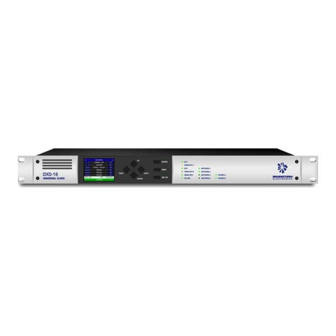
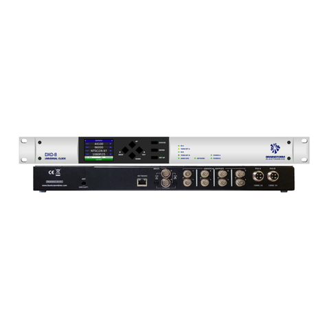
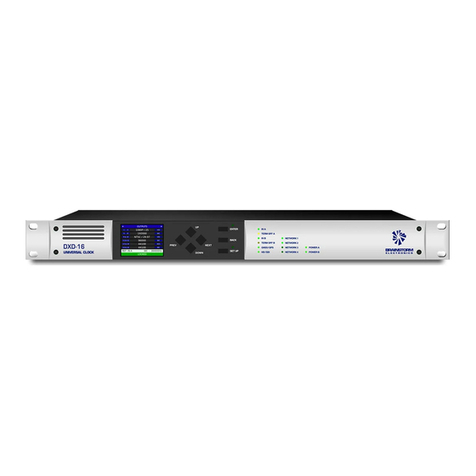
Brainstorm Electronics DXD-8 User manual

DXD/LTC
LTC option
for the DXD-8 & DXD-16 Universal Clocks
Operations manual
Version 2.10
January 2021
All materials herein © Brainstorm Electronics, Inc.
Brainstorm Electronics reserves the right to change or modify the contents of this manual at any time.
Brainstorm Electronics, Inc.
www.brainstormtime.com

Page 2
DXD/LTC User Manual (rev 2.10)
1. Introduction!3...............................................................................................................................
2. Installation!3................................................................................................................................
3. BNC Outputs Menus!3..................................................................................................................
3.1 SIGNAL!3.........................................................................................................
3.2 SOURCE!3........................................................................................................
3.3 RISE/FALL TIME!3.............................................................................................
4. Time Code Menus!4.....................................................................................................................
4.1 SMPTE 2059 Setup (Menu 8.1)!4....................................................................................
4.1.1 Daily Jam Time:!4...........................................................................................
4.1.2 JAM TIMES RECALCULATE:!4.........................................................................
4.2 TC Generator 1 (Menu 8.2)!4........................................................................................
4.2.1 TCG 1 Settings (MENU 8.2.1)!4......................................................................
4.2.1.1 OPERATING MODE!4.............................................................................
4.2.1.3 COLOR FRAMING!5...............................................................................
4.2.1.4 STOP HOLD FRAMES!5...........................................................................
4.2.2 TCG 1 OPERATIONS (MENU 8.2.2)!5............................................................
4.2.2.1 MOTION COMMAND!5.........................................................................
4.2.2.2 CUE POINT!5.........................................................................................
4.3 TC Generator 2 (menu 8.3)!5.........................................................................................
5. GPIO (DXD-16 only)!5..................................................................................................................
5.1 GPIO Inputs!5...................................................................................................
5.2 GPIO Outputs!5................................................................................................
6. Time & Date Display - Main Rotation!6..........................................................................................
7. Outputs Display - Main Rotation!6.................................................................................................
8. Times Display - Status Mode!6......................................................................................................
9. Appendix!7.................................................................................................................................
9.1 APPENDIX A: USING A 75ΩUNBALANCED OUTPUT!7.....................................
9.2 APPENDIX B: BNC OUTPUT LEVEL!7..................................................................
9.3 APPENDIX C: DB-25 CONNECTOR (DXD-16 ONLY)!7........................................
Table of Content

DXD/LTC User Manual (rev 2.10)
Page 3
1. Introduction
The DXD/LTC option is available for both DXD models, the DXD16 and the DXD-8.
This firmware can generate 2 separate streams of time code simultaneously at different formats. Each stream can be set as a
Time Of Day time code generator or as a simple Run/Stop/Cue generator locked to the currently selected reference.
The DXD/LTC transmits SMPTE 2059-2 "Synchronization Metadata" Management Messages on any PTP port where the SMPTE
ST2059 Profile has been enabled.
2. Installation
Before using the DXD/LTC, be sure to update your DXD unit with the latest firmware, available on the Brainstorm website. The
DXD/LTC will not operate with firmware older than 2.10.
When you purchased the DXD/LTC option, you received a unique authorization key, a series of 4 numbers, separated by
periods. This key is only valid for the model and serial number used when you placed the order.
Enter this key in the FEATURE KEYS menu (10.5 on the DXD-8 and 11.5 on the DXD-16), under the main UTILITY menu. On the
DXD-8, be sure to enter it in the TIME CODE line.
After entering the authorization key, a message will ask you to confirm setting the feature key now, followed by another
message confirming that the feature key has been set. This authorization procedure only needs to happen once, even with
subsequent firmware updates. Keep that key handy in case you accidentally change it in the Feature Key menu.
Once the Feature Key has been properly entered, several new menus will become accessible such as the TIME CODE menus.
Other menus will also be affected.
3. BNC Outputs Menus
3.1 SIGNAL
The BNC Outputs menus have a new choice for SIGNAL: Time Code.
3.2 SOURCE
After selecting Time Code as the type of signal for this group of outputs, either of the 2 Time
Code Generators can be selected: TCG1 or TCG2
3.3 RISE/FALL TIME
Choices are available for the output waveform with rise and fall times ranging from 1µsec (square wave) to 50µsec (EBU).
The default value is 40 µsec (SMPTE).
NOTE
On the DXD-16, 2 balanced outputs are available on the DB-25 connector (see appendix C), regardless of how the BNC
outputs are configured. The BNC connectors can be used for unbalanced signal when additional outputs are required.
On the DXD-8, only unbalanced BNC outputs are available.

Page 4
DXD/LTC User Manual (rev 2.10)
4. Time Code Menus
4.1 SMPTE 2059 Setup (Menu 8.1)
4.1.1 DAILY JAM TIME:
The Daily Jam is a process where the time code generator realigns precisely with the epoch (midnight
on Jan 1, 1970). This process occurs everyday, at the same time, as set in the DAILY JAM TIME field.
The value entered in the DAILY JAM TIME field is the amount of time after midnight, local time, at
which the daily jam will occur.
Adjustments can be made in 10 minutes increments. Default value is 01 Hrs 00 Min, i.e. 1:00AM,
local time.
4.1.2 JAM TIMES RECALCULATE:
Pressing the ENTER key while “Press Enter to Jam” is selected will cause the DXD to recalculate both Jam Times, the time of the Previous
Daily Jam Event and the time of the Next Daily Jam Event.
For time code, the Previous Daily Jam Event is the generator’s anchor point, until the Next Daily Jam Event. When the local time is too
close to the set Daily Jam Time, a manual change will not occur until the next day. By forcing the DXD to recalculate both jam times
manually, the operator has the option to make an immediate change.
NOTES ON DAILY JAM AND NTSC DRIFT:
The Daily Jam will occur at the set time, no matter what format time code is generated. With 24, 25 or 30 ND time code, there will be
no correction as each second is divided in a whole number of frames. However, that is not the case with 29.97. Even when using Drop
Frame (i.e. skipping 2 frames on every minute not divisible by 10) a correction will be required as 29.97 time code is actually running
at 29.97002997002… fps (30 x (1000/1001). For that reason, when maintaining a time code sequence longer than 24 hours, it
should be jammed to local time daily. Per ST2059-1, a Daily Jam is usually set to occur at an operationally convenient time, typically
during the early morning hours in local time. Default value on the DXD is set at 1:00AM.
4.2 TC Generator 1 (Menu 8.2)
4.2.1 TCG 1 SETTINGS (MENU 8.2.1)
4.2.1.1 OPERATING MODE
The choices for Operating Mode are Time-Of-Day or Simple/Run/Stop/Cue.
•Time-Of-Day means that the time code addresses will match the time-of-day, or System Time in the case of the DXD,
expressed in Local Time. This generator can be stopped and restarted. However, when restarted, the generator will jump to
the current time of day.
•Simple Run/Stop/Cue is like a traditional time code generator. A Cue Point can be set in menu 8.2.2. Unlike the TOD
generator, when restarting, the generator will resume where it stopped, unless of course the CUE command was initiated
before START.
4.2.1.2 TIME CODE RATE/COUNT
This field has the following choices:
•23.976/24
•24/24
•25/25
•29.97/DF
•29.97/NDF
•30/DF
•30/NDF

DXD/LTC User Manual (rev 2.10)
Page 5
4.2.1.3 COLOR FRAMING
Color Framing can only be enabled for PAL and NTSC formats, i.e. when the Rate/Count is set to:
•25/25
•29.97/DF
•29.97/NDF
Enabling Color Framing means that the color field sequence of the time code will be aligned with the PTP epoch (midnight on
Jan 1, 1970) per ST2059. The color field sequence can have a duration a 4 or 8 fields (2 or 4 frames).
4.2.1.4 STOP HOLD FRAMES
This represents the number of consecutive frame periods during which the DXD will issue the stopped time code value ("freeze
frame") whenever the generator stops or cues.
This number varies from 1 to 99 or even CONTINUOUS. The default value is 10.
4.2.2 TCG 1 OPERATIONS (MENU 8.2.2)
4.2.2.1 MOTION COMMAND
The Time Code Generator can be controlled different ways: Via the TIME & DATE Main
Rotation Page, GPIO or menu 8.2.2. The choices for MOTION COMMAND are:
•Press ENTER to RUN
•Press ENTER to STOP
•Press ENTER to CUE (for Simple Run/Stop/Cue generator only).
Simply select a command and hit the ENTER key.
4.2.2.2 CUE POINT
This menu is used to enter a CUE point to be used when the TCG is set to Simple Run/Stop/Cue.
In that mode, using the CUE command will cause the TCG to return to the set CUE point.
4.3 TC Generator 2 (menu 8.3)
Menus 8.3 have the exact same functions as 8.2 but for the TCG 2.
5. GPIO (DXD-16 only)
New functions have been added to the DXD-16 GPIOs.
5.1 GPIO INPUTS
TCG 1 & 2 Run
TCG 1 & 2 Stop
TCG 1 & 2 Cue
5.2 GPIO OUTPUTS
TCG 1 Running
TCG 2 Running
Daily Jam Hold
Daily Jam Pulse
The CUE command (TGIO Input) only applies to the time code generator(s) set to Run/Stop/Cue, not Time-Of-Day.
For detailed informations on the GPIO circuitry, please see the DXD-16 Owners Manual.

Page 6
DXD/LTC User Manual (rev 2.10)
6. Time & Date Display - Main Rotation
With the DXD/LTC installed, menu 7.3 includes the 2 Time Code Generators to the selection of times to be displayed on the
DATE & TIME Main Rotation page, in the upper and lower parts of the display.
•Time-Of-Day TCG: If the selected Time Code Generator (TCG) is set as Time-Of-Day, the line
directly under the time code reader will say ‘ENTER=Run/Stop’.
•Simple Run/Stop/Cue TCG: If it is set as Simple Run/Stop/Cue it will say ‘UP=CUE,
ENTER=Run/Stop’ since that generator has the option to start from a preset CUE point.
Note that the frame numbers will be replaced on the display by ‘FF’, when the generator is
running and will be displayed when it is stopped. This does not affect the output of course.
Also, the colons between the hours, minutes, seconds and frames will be replaced by semicolons when generating Drop Frame
time code, for easy identification.
The blue box on the left of the display identifies the source of the time code (TCG1 or TCG2).
The blue box on the right of the display identifies the rate and frame count. Here is how they are identified in the blue box:
!•23.976/24!24PD!(Pulled Down)..............
!•24/24!24!.......................
!•25/25!25!.......................
!•29.97/DF!29DF!(Dropped Frame)................
!•229.97/NDF!29ND!(NonDrop)...........
!•30/DF!30DF!(Dropped Frame).....................
!•30/NDF!30ND!(NonDrop)..................
7. O u t p u t s D i s p l a y - M a i n R o t a t i o n
When selecting a TCG in one of the BNC Outputs menus, it will be shown on the OUTPUTS
page of the main rotation display, along with the selected format in the blue box on its right.
8. Times Display - Status Mode
Several new lines were added to the TIMES Status page with the DXD/LTC option:
•TC Gen 1: This line displays the date and address of the first time code generator. As it is a live display, if time code is
running, the frame numbers are replaced by the letters ‘ff’ like on the TIME & DATE display. When the generator is stopped,
the frame numbers are displayed. The right column shows the time code format as detailed in ch 6 above.
•TC Gen 2: This line is identical to the one above, but for the second Time Code Generator. In the illustration to the right, TC
Gen 2 is stopped at the CUE point which is why the frame numbers are displayed.
In each case the date will be displayed for a generator in Time-Of-Day mode, but will be blanked out (dashes) in Start/Stop/
Cue mode.
•Prev Daily: The time of the PREVIOUS DAILY JAM event is displayed on this line, along with
the date. Time code is always LOCAL TIME which is confirmed in the right column.
•Next Daily: The time of the NEXT DAILY JAM event is displayed on this line, along with the
date. Time code is always LOCAL TIME which is confirmed in the right column.

DXD/LTC User Manual (rev 2.10)
Page 7
9. Appendix
9.1 APPENDIX A: USING A 75ΩUNBALANCED OUTPUT
Many time code readers will accept a 75Ωsignal. Otherwise, a balun will need to be used.
The other aspect of the BNC output is that it is unbalanced. Here again it should be no problem with most readers using the
following wiring (connection between pins 1 & 3, green line, is optional).
9.2 APPENDIX B: BNC OUTPUT LEVEL
•1.97Vp-p into 75 ohms (nominal 2Vp-p).
•3.94Vp-p unterminated (nominal 4Vp-p).
9.3 APPENDIX C: DB-25 CONNECTOR (DXD-16 ONLY)
As shown on the illustration below, the DB-25 connector provides 2 balanced time code outputs in addition to 3 General
Purpose Inputs (GPI) and 4 General Purpose Outputs (GPO). Time Code outputs are only available with the LTC option
installed.
TCG1 is connected using pins 9 (+), 22 (-) & 21 (GND); TCG2 is connected using pins 23 (+), 11 (-) & 10 (GND).
•Output level: nominal 2Vp-p differential.
This connector is not available on the DXD-8.
12
3
Sleeve
Tip
Copper mesh
Insulated copper wire
COAXIAL CABLE
13
12
11
10
9
8
7
6
5
4
3
2
1
Reserved
Reserved
TC Out 2 -
GND
TC Out 1 +
1 PPS Out
Reserved
GPI 3
GPI 2
GPI 1
GPO 3 +
GPO 2 +
GPO 1 +
25
24
23
22
21
20
19
18
17
16
15
14
GND
GND
TC Out 2 +
TC Out 1 -
GND
GND
GND
GND
GND
GPO 3 - (GND)
GPO 2 - (GND)
GPO 1 - (GND)
13
25
1
14
Other manuals for DXD-8
3
This manual suits for next models
3
Table of contents
Other Brainstorm Electronics Clock manuals

Brainstorm Electronics
Brainstorm Electronics DXD/PTP User manual

Brainstorm Electronics
Brainstorm Electronics DXD-16 User manual

Brainstorm Electronics
Brainstorm Electronics DXD-8 User manual

Brainstorm Electronics
Brainstorm Electronics DXD-8 User manual

Brainstorm Electronics
Brainstorm Electronics DXD-8 User manual